Page 1090 of 4378
1. Lubricate the piston pin and piston pin bore with clean engine oil.
2.
NOTE: The connecting rod can be installed in either direction.
Position the piston pin in the bore aligned with the connecting rod bore.
3. Using the special tool, press the piston pin into the piston and rod assembly. �K�l�j . 2 �b�a
32003 Mustang Workshop Manual
17. 11. 2011file:///C:/Ford/2000 - 2004/tsocache/SHEF_4464/S3B~us~en~ ...
Page 1092 of 4378
ASSEMBLY
Engine
SECTION 303-
01A: Engine — 3.8L 2003 Mustang Workshop Manual Special Tool(s)
Slide Hammer
307-
005 (T59L- 100-B) Remover Adapter, Vibration
Damper
303-
176 (T82L-6316- B) Installer, Crankshaft Front Seal
303-
474 (T94P-6701- AH) Replacer, Steering Pump
Pulley
211-
009 (T65P-3A733- C) Engine Lift Bracket Set
303-
D095 (D94L-6001- A) Replacer, Rear Crankshaft
Seal
303-
516 (T95P-6701- BH) Spacer, Rear Crank Seal
Replacer
303-
561 (T96T-6701- B) Adapter, Crankshaft Rear Seal
(Use only the adapter retaining
bolts)
303-
518 (T95P-6701- DH) �K�l�j . 1 �b�a
282003 Mustang Workshop Manual
17. 11. 2011file:///C:/Ford/2000 - 2004/tsocache/SHEF_4464/S3B~us~en~ ...
Page 1093 of 4378

CAUTION: The moving components must be lubricated with clean engine oil before
assembly.
CAUTION: The components with oil holes must be correctly aligned with the oil feed
holes.
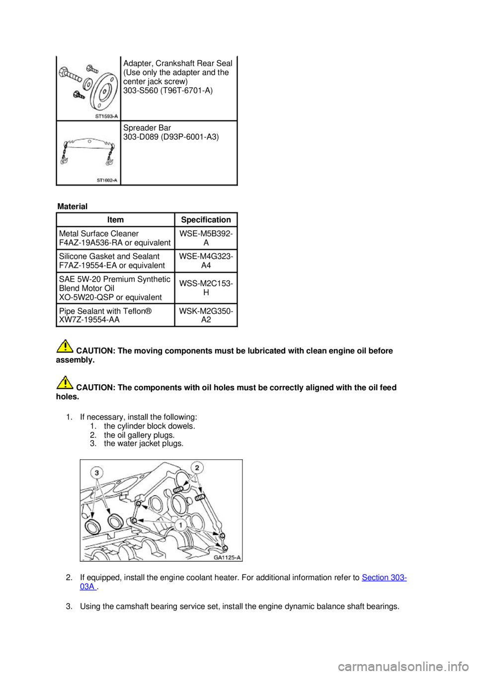
1. If necessary, install the following: 1. the cylinder block dowels.
2. the oil gallery plugs.
3. the water jacket plugs.
2. If equipped, install the engine coolant heater. For additional information refer to Section 303 -
03A .
3. Using the camshaft bearing service set, install the engine dynamic balance shaft bearings. Adapter, Crankshaft Rear Seal
(Use only the adapter and the
center jack screw)
303-
S560 (T96T-6701- A) Spreader Bar
303-
D089 (D93P-6001- A3)
Material Item Specification
Metal Surface Cleaner
F4AZ-
19A536- RA or equivalent WSE-
M5B392-
A Silicone Gasket and Sealant
F7AZ-
19554- EA or equivalent WSE-
M4G323-
A4 SAE 5W-
20 Premium Synthetic
Blend Motor Oil
XO- 5W20-QSP or equivalent WSS-
M2C153-
H Pipe Sealant with Teflon®
XW7Z-19554-
AA WSK-
M2G350-
A2 �K�l�j . 2 �b�a
282003 Mustang Workshop Manual
17. 11. 2011file:///C:/Ford/2000 - 2004/tsocache/SHEF_4464/S3B~us~en~ ...
Page 1094 of 4378
4. Using the camshaft bearing service set, install the camshaft bearings.
5. Install the following:
1. the engine dynamic balance shaft bearing cover.
2. the camshaft bearing cover.
6. CAUTION: Do not damage the camshaft lobes when installing the camshaft.
Install the camshaft and the camshaft spacer. �K�l�j . 3 �b�a
282003 Mustang Workshop Manual
17. 11. 2011file:///C:/Ford/2000 - 2004/tsocache/SHEF_4464/S3B~us~en~ ...
Page 1095 of 4378
7. Install the camshaft thrust plate.
1. Position the camshaft thrust plate.
2. Install the bolts.
8. Turn the camshaft so that the timing mark is at 12 o'clock and install the engine dynamic balance shaft assembly into the cylinder block. Turn the engine balance shaft driven gear so
that the timing mark aligns up with the timing mark on the engine balance shaft drive gear.
9. NOTE: If correctly aligned, the engine dynamic balance shaft keyway will be at 12 o'clock and
the camshaft keyway will be at 6 o'clock on the camshaft.
Install the bolts.
10. CAUTION: Make sure the components are installed in the correct location.
NOTE: Lubricate the crankshaft main bearings prior to installation.
Install the crankshaft upper main bearings and the crankshaft upper thrust main bearing. �K�l�j . 4 �b�a
282003 Mustang Workshop Manual
17. 11. 2011file:///C:/Ford/2000 - 2004/tsocache/SHEF_4464/S3B~us~en~ ...
Page 1098 of 4378
CAUTION: Do not damage the cylinder wall with the sharp edges of the connecting
rod.
Install the piston with the arrow on the piston face pointing toward the front of the engine.
16. CAUTION: Inspect the connecting rod bearing clearance. For additional information,
refer to Section 303 - 00 .
CAUTION: The connecting rod cap will fit only one way.
Position the connecting lower rod bearing and the connecting rod cap on the connecting rod
and the crankshaft journal.
17. Install the rod caps. Tighten the bolts in three stages: �zStage 1: Tighten to 25 Nm (18 lb- ft).
�z Stage 2: Tighten to 45 Nm (33 lb- ft).
�z Stage 3: Tighten an additional 105 degrees. 18. Install the remaining pistons and the connecting rods. �K�l�j . 7 �b�a
282003 Mustang Workshop Manual
17. 11. 2011file:///C:/Ford/2000 - 2004/tsocache/SHEF_4464/S3B~us~en~ ...
Page 1101 of 4378
28. Remove the retaining pin.
CAUTION: The components removed should be marked for location. Make sure the used
parts are installed in the correct location.
29. NOTE: Install the new cylinder head gaskets with the small hole to the front of the engine.
Using new gaskets, install the RH and the LH cylinder heads.
30. CAUTION: Always use new bolts.
NOTE: Lubricate the bolts with clean engine oil prior to installation.
Position the new bolts. 1. Position the new long bolts.
2. Position the new short bolts. �K�l�j . 10 �b�a
282003 Mustang Workshop Manual
17. 11. 2011file:///C:/Ford/2000 - 2004/tsocache/SHEF_4464/S3B~us~en~ ...
Page 1102 of 4378
31. Tighten the bolts in three stages in the sequence shown:
�zStage 1: Tighten to 20 Nm (15 lb- ft).
�z Stage 2: Tighten to 40 Nm (30 lb- ft).
�z Stage 3: Tighten to 50 Nm (37 lb- ft).
32. CAUTION: Do not loosen all of the bolts at one time. Each bolt must be loosened
and tightened prior to working on the next bolt in the sequence.
Tighten the bolts in four stages in the sequence shown: short bolts numbered 2, 4, 6 and 8:
�zStage 1: Tighten to 25 Nm (18 lb- ft).
�z Stage 2: Tighten an additional 180 degrees.
Long bolts numbered 1, 3, 5 and 7:
�z Stage 3: Tighten to 45 Nm (33 lb- ft).
�z Stage 4: Tighten an additional 180 degrees.
33. NOTE: Lubricate the valve tappets with clean engine oil prior to installing.
Install the valve tappets. �K�l�j . 11 �b�a
282003 Mustang Workshop Manual
17. 11. 2011file:///C:/Ford/2000 - 2004/tsocache/SHEF_4464/S3B~us~en~ ...