Page 2612 of 4378
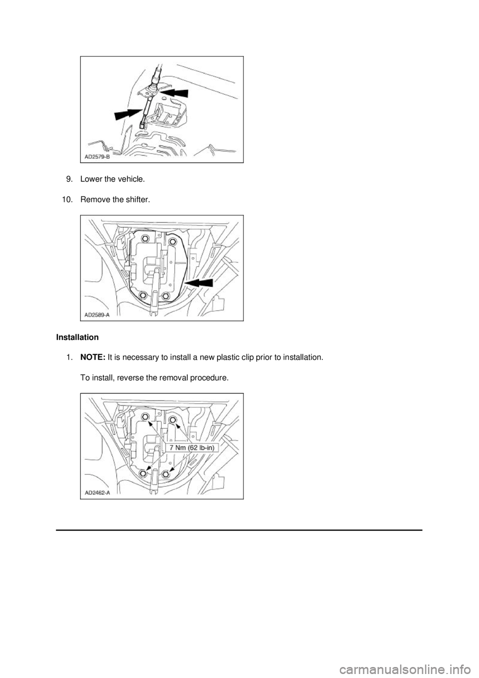
9. Lower the vehicle.
10. Remove the shifter.
Installation 1. NOTE: It is necessary to install a new plastic clip prior to installation.
To install, reverse the removal procedure. �K�l�j . 3 �b�a
42003 Mustang Workshop Manual
18. 11. 2011file:///C:/Ford/2000 - 2004/tsocache/SHEF_2748/S3B~us~en~ ...
Page 2663 of 4378
REMOVAL AND INSTALLATION
Disc and Pressure Plate —
4.6L (4V) Engine
1. Disconnect the battery ground cable. For additional information, refer to Section 414 - 01 .
2. Remove the transmission. For additional information, refer to Section 308 - 03C .
3. Remove the starter. 1. Remove the terminal cap.
2. Remove the nuts.
3. Remove the wires and position them aside.
4. Remove the two bolts and the starter.
4. Remove the clutch cable clip, then pull the cable through the clutch housing.
SECTION 308-
01: Clutch 2003 Mustang Workshop Manual Special Tool(s)
Clutch Aligner
308-
020 (T74P-7137- K)
Material Item Specification
Premium Long Life Grease
XG
-1-C ESA-
M1C75- B �K�l�j . 1 �b�a
42003 Mustang Workshop Manual
18. 11. 2011file:///C:/Ford/2000 - 2004/tsocache/SHEF_2308/S3B~us~en~ ...
Page 2684 of 4378
10. Remove the screw and the dust shield.
11. Pull the clutch release lever cable (7K553) and remove from the clutch release lever (7515).
12. Remove the C-
clip from the clutch release lever cable and remove the clutch release lever
cable from the vehicle.
Installation 1. To install, reverse the removal procedure. �K�l�j . 3 �b�a
52003 Mustang Workshop Manual
18. 11. 2011file:///C:/Ford/2000 - 2004/tsocache/SHEF_2308/S3B~us~en~ ...
Page 2692 of 4378

Transmission Identification
The transmission identification tag is located under the lower left bolt that retains the extension 50 7230 Reverse shift fork
51 7240 Reverse gear shift rail
52 7230 Fifth gear shifter fork
53 357479-S15 Split pin
54 371197-
S Reverse gearshift lever retaining clip
55 7K002 Reverse gearshift lever
56 7E485 Reverse positioning spring
57 7005 Case
58 87675-
S Case plug
59 74113-
S Plug
60 15520 Reversing lamp switch
61 7K024 Shift lever reverse pin
62 7E397 Reverse gear overtravel stop
63 7141 Reverse idler gear and bushing
64 7140 Reverse idler gear shaft
65 357479-S15 Pin
66 7K316 Fifth speed driven gear
67 7H150 Output shaft speed wheel
68 7034 Vent
69 E800152-S72 Bolt
70 7A039 Extension housing
71 7K381 Extension plug
72 7052 Extension housing fluid seal
73 372720-
S Detent ball
74 7234 Shifter detent spring
75 7F018 Gearshift offset lever
76 7K453 Gearshift shaft bushing
77 7A443 Bolt
78 7C108 Gearshift lower boot clamp
79 7210 Gearshift lever
80 7277 Gearshift lever boot
81 N602187-
S100 Bolt
82 7050 Input shaft bearing retainer
83 7052 Input shaft seal
84 7025 Input bearing assembly
85 7017 Input shaft
86 7118 Roller bearing (15 req'd)
87 7L357 Input shaft bearing spacer �K�l�j . 4 �b�a
52003 Mustang Workshop Manual
18. 11. 2011file:///C:/Ford/2000 - 2004/tsocache/SHEF_2308/S3B~us~en~ ...
Page 2712 of 4378
14. Remove the fifth speed synchronizer retaining snap ring, the thrust washer (7G042), the reverse
brake ring (7M000), and the synchronizer blocking ring (7107).
15. Remove the fifth speed cluster gear (7144), the synchronizer blocking ring (7107), the synchronizer assembly (7124), and the fifth gear shifter fork (7230) as an assembly.
16. Remove the reverse gearshift lever retaining clip.
17. NOTE: Do not remove the reverse gearshift lever (7K002) at this time.
Using a TORX® bit driver, remove the shift lever reverse pin (7K024). �K�l�j . 5 �b�a
112003 Mustang Workshop Manual
18. 11. 2011file:///C:/Ford/2000 - 2004/tsocache/SHEF_2308/S3B~us~en~ ...
Page 2748 of 4378
21.
NOTE: If not done so previously, soak the blocking ring in transmission fluid for ten minutes.
Install the fifth speed cluster gear, the synchronizer blocking ring, the synchronizer assembly,
and the fifth gear shifter fork as an assembly.
22. CAUTION: To prevent component damage when installing the extension housing
(7A039), the alignment tab on the reverse brake ring (7M000) must engage the alignment
slot in the extension housing.
NOTE: If not done so previously, soak the blocking ring in transmission fluid for ten minutes.
Install the synchronizer blocking ring, the reverse brake ring, the thrust washer, and the fifth
speed synchronizer retaining snap ring.
23. Apply pipe sealant to the reversing lamp switch threads and install the switch.
24. Install the reverse gearshift lever retaining clip. �K�l�j . 8 �b�a
142003 Mustang Workshop Manual
18. 11. 2011file:///C:/Ford/2000 - 2004/tsocache/SHEF_2308/S3B~us~en~ ...
Page 2963 of 4378

GENERAL PROCEDURES
Spring Lock Couplings
Disconnect
WARNING: Do not smoke or carry lighted tobacco or open flame of any type when
working on or near any fuel- related components. Highly flammable mixtures are always present
and may be ignited, resulting in possible personal injury.
WARNING: Fuel in the fuel system remains under high pressure even when the engine is
not running. Before servicing or disconnecting any of the fuel lines or fuel system components,
the fuel system pressure must be relieved to prevent accidental spraying of fuel, causing
personal injury or a fire hazard.
1. Relieve the fuel system pressure. For additional information, refer to Pressure Relief in this
section.
2. Remove the fuel tube clip.
SECTION 310-
00: Fuel System — General Information 2003 Mustang Workshop Manual Special Tool(s)
Disconnect Tool, Spring Lock
Coupling (3/8 inch yellow)
310-
D004 (D87L-9280- A) or
equivalent Disconnect Tool, Spring Lock
Coupling (1/2 inch green)
310-
D005 (D87L-9280- B) or
equivalent
Material Item Specification
SAE 5W-
20 Super Premium
Synthetic Blend Motor Oil
XO- 5W20- QSP or equivalent WSS-
M2C153-
H �K�l�j . 1 �b�a
32003 Mustang Workshop Manual
18. 11. 2011file:///C:/Ford/2000 - 2004/tsocache/SHEF_2308/S3B~us~en~ ...
Page 2965 of 4378
Connect
1. NOTE: Inspect and clean both the coupling ends. Lubricate the O- ring seals with clean engine
oil.
Connect the fitting.
�zPull on the fitting to make sure it is fully engaged.
�z Install the safety clip. �K�l�j . 3 �b�a
32003 Mustang Workshop Manual
18. 11. 2011file:///C:/Ford/2000 - 2004/tsocache/SHEF_2308/S3B~us~en~ ...
 Engine
1. Disconnect the battery ground cable. For additional information, refer to Section 414 - 01 .
2. Remove the transmission. F")
 and remove from the clutch release lever (7515).
12. Remove the C-
clip from the clutch release lever cable")
, the reverse
brake ring (7M000), and the synchronizer blocking ring (7107).
15. Remove the fifth speed cluster")

