Page 1980 of 4378
12. Remove the fuel supply manifold and fuel injectors as an assembly.
13. Remove the anti-
rotation clips and the fuel injectors from the fuel supply manifold.
14. NOTE: Always install new O- rings.
NOTE: Lubricate the O- rings with clean engine oil to aid installation.
NOTE: Make sure the anti- rotation clips are installed.
To install, reverse the removal procedure. �K�l�j . 3 �b�a
42003 Mustang Workshop Manual
18. 11. 2011file:///C:/Ford/2000 - 2004/tsocache/SHEF_4464/S3B~us~en~ ...
Page 1991 of 4378

REMOVAL AND INSTALLATION
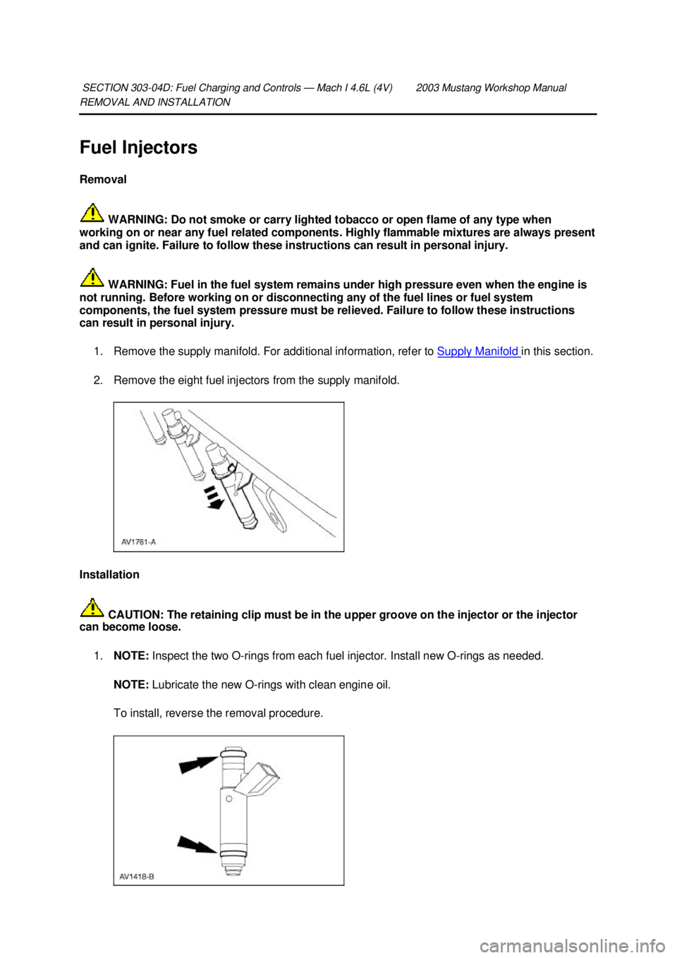
Fuel Injectors
Removal
WARNING: Do not smoke or carry lighted tobacco or open flame of any type when
working on or near any fuel related components. Highly flammable mixtures are always present
and can ignite. Failure to follow these instructions can result in personal injury.
WARNING: Fuel in the fuel system remains under high pressure even when the engine is
not running. Before working on or disconnecting any of the fuel lines or fuel system
components, the fuel system pressure must be relieved. Failure to follow these instructions
can result in personal injury.
1. Remove the supply manifold. For additional information, refer to Supply Manifold in this section.
2. Remove the eight fuel injectors from the supply manifold.
Installation CAUTION: The retaining clip must be in the upper groove on the injector or the injector
can become loose.
1. NOTE: Inspect the two O- rings from each fuel injector. Install new O- rings as needed.
NOTE: Lubricate the new O- rings with clean engine oil.
To install, reverse the removal procedure.
SECTION 303-
04D: Fuel Charging and Controls — Mach I 4.6L (4V) 2003 Mustang Workshop Manual �K�l�j . 1 �b�a
22003 Mustang Workshop Manual
18. 11. 2011file:///C:/Ford/2000 - 2004/tsocache/SHEF_4464/S3B~us~en~ ...
Page 2096 of 4378
REMOVAL AND INSTALLATION
Exhaust Gas Recirculation (EGR) Valve —
Cobra
Removal and Installation 1. Disconnect the accelerator cable and the speed control cable.
2. Remove the accelerator cable bracket bolts.
3. Release the clip and position the accelerator cable bracket and the cables aside.
4. Disconnect the electrical connectors from the fuel pulse damper, EGR vacuum regulator solenoid, supercharger bypass vacuum solenoid, and the differential pressure feedback EGR
system.
SECTION 303-
08: Engine Emission Control 2003 Mustang Workshop Manual �K�l�j . 1 �b�a
42003 Mustang Workshop Manual
18. 11. 2011file:///C:/Ford/2000 - 2004/tsocache/SHEF_4464/S3B~us~en~ ...
Page 2125 of 4378
REMOVAL AND INSTALLATION
Air Cleaner Element —
3.8L
Removal and Installation 1. Remove the air cleaner outlet tube. For additional information, refer to Air Cleaner Outlet Pipe —
3.8L in this section
2. Disconnect the connector.
3. Remove the mass air flow (MAF) sensor. 1. Release the clips.
2. Remove the MAF sensor assembly.
4. Remove the air cleaner element.
5. To install, reverse the removal procedure.
SECTION 303-
12: Intake Air Distribution and Filtering 2003 Mustang Workshop Manual �K�l�j . 1 �b�a
22003 Mustang Workshop Manual
18. 11. 2011file:///C:/Ford/2000 - 2004/tsocache/SHEF_4464/S3B~us~en~ ...
Page 2127 of 4378
REMOVAL AND INSTALLATION
Air Cleaner Element —
4.6L (2V)
Removal and Installation 1. Remove the air cleaner outlet tube (9B659). For additional information, refer to Air Cleaner Outlet Pipe — 4.6L (2V) in this section.
2. Remove the mass air flow (MAF) assembly. 1. Release the clip.
2. Remove the MAF sensor assembly and position aside.
3. Remove the air cleaner element.
4. To install, reverse the removal procedure.
SECTION 303-
12: Intake Air Distribution and Filtering 2003 Mustang Workshop Manual �K�l�j . 1 �b�a
22003 Mustang Workshop Manual
18. 11. 2011file:///C:/Ford/2000 - 2004/tsocache/SHEF_4464/S3B~us~en~ ...
Page 2136 of 4378
12. Remove the throttle body and spacer assembly.
13. Release the clip and position the accelerator cable bracket and the cables aside.
14. Disconnect the electrical connectors from the fuel pulse damper, EGR vacuum regulator
solenoid, supercharger bypass vacuum solenoid, and the differential pressure feedback EGR
system.
15. Disconnect the vacuum hoses from the differential pressure feedback EGR system. �K�l�j . 3 �b�a
102003 Mustang Workshop Manual
18. 11. 2011file:///C:/Ford/2000 - 2004/tsocache/SHEF_4464/S3B~us~en~ ...
Page 2251 of 4378
REMOVAL AND INSTALLATION
Supercharger Bypass Vacuum Solenoid
Removal and Installation
1. Remove the supercharger bypass vacuum solenoid. 1. Disconnect the vacuum hoses.
2. Disconnect the electrical connector.
3. Unclip the supercharger bypass vacuum solenoid from the vacuum accessory bracket.
2. To install, reverse the removal procedure.
SECTION 303-
14: Electronic Engine Controls 2003 Mustang Workshop Manual �K�l�j . 1 �b�a
12003 Mustang Workshop Manual
18. 11. 2011file:///C:/Ford/2000 - 2004/tsocache/SHEF_4464/S3B~us~en~ ...
Page 2271 of 4378

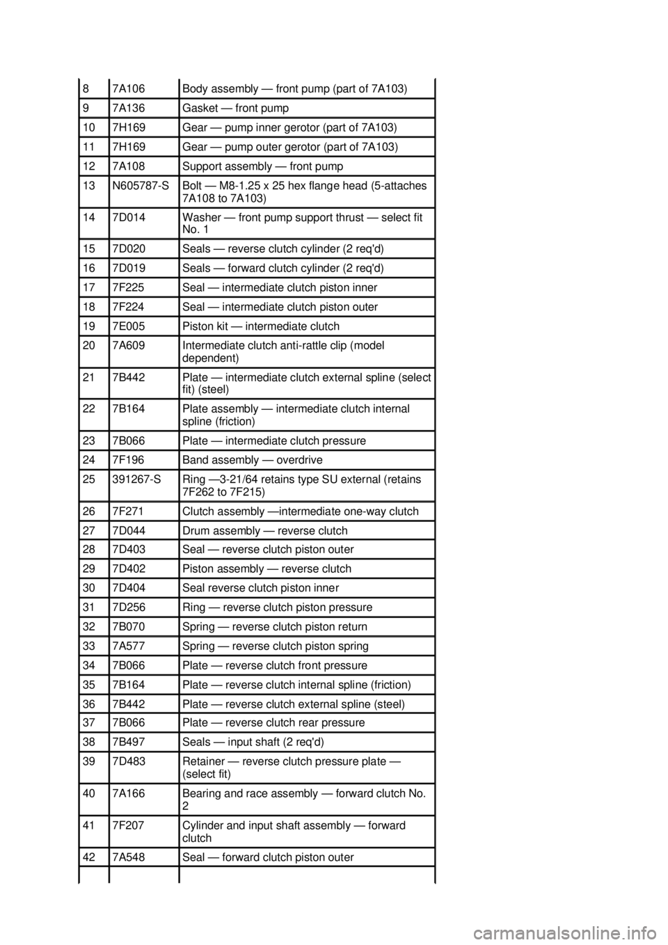
8 7A106 Body assembly —
front pump (part of 7A103) 9 7A136 Gasket —
front pump 10 7H169 Gear —
pump inner gerotor (part of 7A103) 11 7H169 Gear —
pump outer gerotor (part of 7A103) 12 7A108 Support assembly —
front pump 13 N605787-
S Bolt —
M8-1.25 x 25 hex flange head (5- attaches
7A108 to 7A103) 14 7D014 Washer —
front pump support thrust — select fit
No. 1 15 7D020 Seals —
reverse clutch cylinder (2 req'd) 16 7D019 Seals —
forward clutch cylinder (2 req'd) 17 7F225 Seal —
intermediate clutch piston inner 18 7F224 Seal —
intermediate clutch piston outer 19 7E005 Piston kit —
intermediate clutch 20 7A609 Intermediate clutch anti-
rattle clip (model
dependent) 21 7B442 Plate —
intermediate clutch external spline (select
fit) (steel) 22 7B164 Plate assembly —
intermediate clutch internal
spline (friction) 23 7B066 Plate —
intermediate clutch pressure 24 7F196 Band assembly —
overdrive 25 391267-
S Ring —3-
21/64 retains type SU external (retains
7F262 to 7F215) 26 7F271 Clutch assembly —intermediate one-
way clutch 27 7D044 Drum assembly — reverse clutch
28 7D403 Seal —
reverse clutch piston outer 29 7D402 Piston assembly —
reverse clutch 30 7D404 Seal reverse clutch piston inner
31 7D256 Ring —
reverse clutch piston pressure 32 7B070 Spring —
reverse clutch piston return 33 7A577 Spring —
reverse clutch piston spring 34 7B066 Plate —
reverse clutch front pressure 35 7B164 Plate —
reverse clutch internal spline (friction) 36 7B442 Plate —
reverse clutch external spline (steel) 37 7B066 Plate —
reverse clutch rear pressure 38 7B497 Seals —
input shaft (2 req'd) 39 7D483 Retainer —
reverse clutch pressure plate —
( select fit) 40 7A166 Bearing and race assembly —
forward clutch No.
2 41 7F207 Cylinder and input shaft assembly —
forward
clutch 42 7A548 Seal —
forward clutch piston outer �K�l�j . 3 �b�a
82003 Mustang Workshop Manual
18. 11. 2011file:///C:/Ford/2000 - 2004/tsocache/SHEF_2748/S3B~us~en~ ...