Page 1827 of 4378
21. Position the clip and install the bolt.
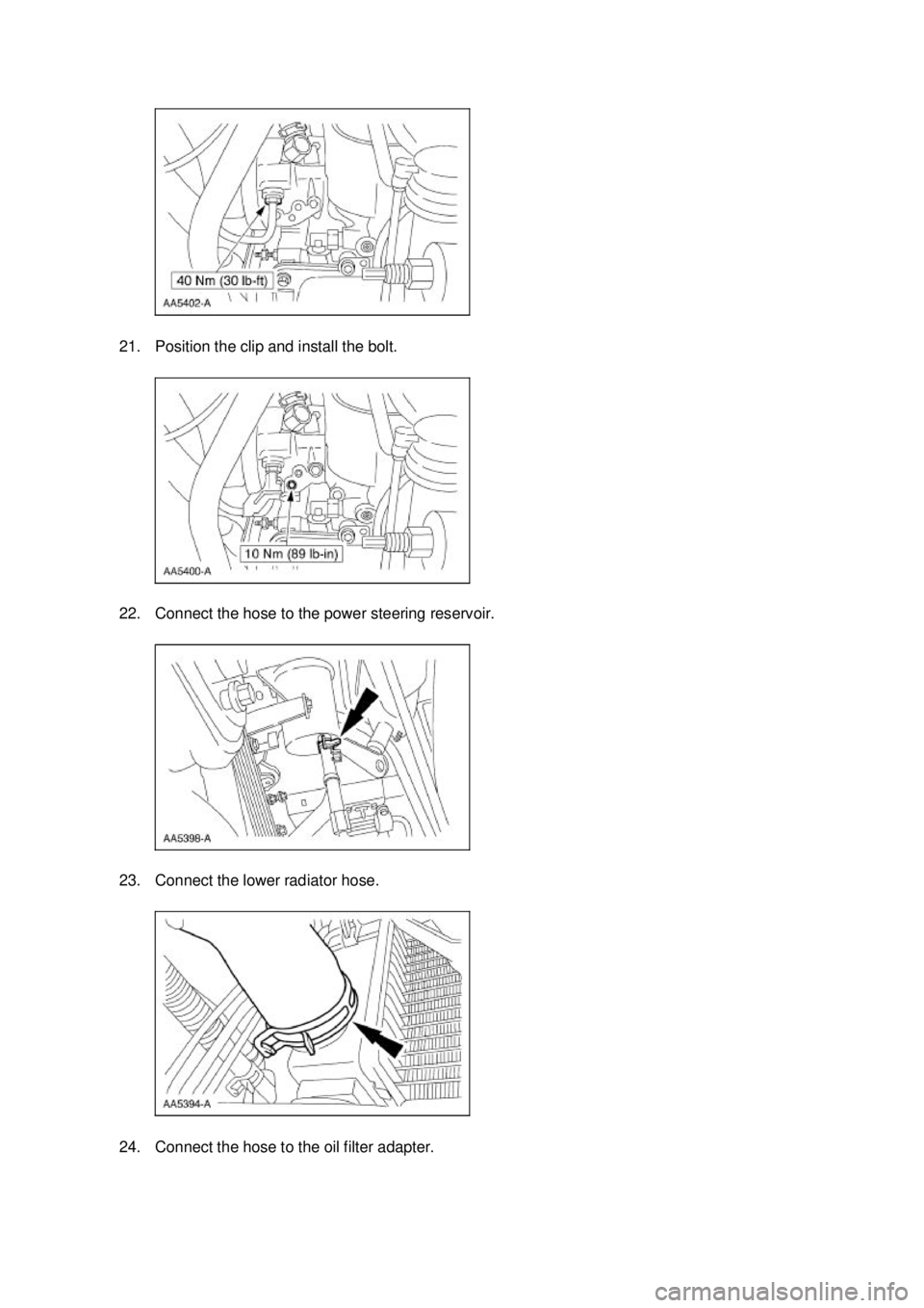
22. Connect the hose to the power steering reservoir.
23. Connect the lower radiator hose.
24. Connect the hose to the oil filter adapter. �K�l�j . 7 �b�a
182003 Mustang Workshop Manual
17. 11. 2011file:///C:/Ford/2000 - 2004/tsocache/SHEF_4464/S3B~us~en~ ...
Page 1875 of 4378
REMOVAL AND INSTALLATION
Bypass Tube —
Cobra
Removal and Installation 1. Drain the engine coolant. For additional information, refer to Cooling System Draining, Filling and Bleeding in this section.
2. Disconnect the radiator upper hose and the radiator lower hose.
3. Remove the supercharger belt. For additional information, refer to Section 303 - 05 .
4. Disconnect the engine coolant temperature sensor electrical connector and unclip the wiring harness from the stud.
5. NOTE: LH is shown, RH is similar.
Remove the coolant bypass nuts.
SECTION 303-
03A: Engine Cooling 2003 Mustang Workshop Manual Material
Item Specification
Motorcraft Premium Gold
Engine Coolant
VC
-7-A (in Oregon VC-7- B)
(yellow color) WSS-
M97B51-
A1 �K�l�j . 1 �b�a
22003 Mustang Workshop Manual
18. 11. 2011file:///C:/Ford/2000 - 2004/tsocache/SHEF_4464/S3B~us~en~ ...
Page 1887 of 4378

REMOVAL AND INSTALLATION
Radiator
Removal and Installation
NOTE:
Radiator removal and installation is similar for both 3.8L and 4.6L vehicles. The art shown in
the procedure is the 4.6L engine.
Mach I
1. Remove the air intake scoop. For additional information, refer to Section 303 - 12 .
All vehicles 2. Drain the engine cooling system. For additional information, refer to Cooling System Draining, Filling and Bleeding in this section.
3. Remove the radiator sight shield. �zRelease the clips.
4. Remove the fan blade, fan motor and fan shroud assembly. For additional information, refer to Cooling Fan Motor and Shroud in this section.
5. Remove the upper radiator hose from the radiator.
SECTION 303-
03A: Engine Cooling 2003 Mustang Workshop Manual Material
Item Specification
Motorcraft Premium Gold
Engine Coolant
VC
-7-A (in Oregon VC-7- B)
(yellow color) WSS-
M97B51-
A1 �K�l�j . 1 �b�a
42003 Mustang Workshop Manual
18. 11. 2011file:///C:/Ford/2000 - 2004/tsocache/SHEF_4464/S3B~us~en~ ...
Page 1924 of 4378

REMOVAL AND INSTALLATION
Fuel Injectors
Removal and Installation
WARNING: Do not smoke or carry lighted tobacco or open flame of any type when
working on or near any fuel related components. Highly flammable mixtures are always present
and may ignite. Failure to follow these instructions may result in personal injury.
WARNING: Fuel in the fuel system remains under high pressure even when the engine is
not running. Before working on or disconnecting any of the fuel lines or fuel system
components, the fuel pressure must be relieved. Failure to follow these instructions may result
in personal injury
1. Remove the supply manifold. For additional information, refer to Supply Manifold in this section.
2. Remove the six fuel injectors from the supply manifold.
3. CAUTION: The retaining clip must be in the upper groove on the injector or the
injector may become loose.
NOTE: Inspect the two O- rings from each fuel injector. Install new O- rings as needed.
NOTE: Lubricate the new O- rings with clean engine oil to aid installation.
To install, reverse the removal procedure.
SECTION 303-
04A: Fuel Charging and Controls — 3.8L 2003 Mustang Workshop Manual Material
Item Specification
SAE 5W-
20 Premium Synthetic
Blend Motor Oil
XO- 5W20-QSP or equivalent WSS-
M2C153-
H �K�l�j . 1 �b�a
22003 Mustang Workshop Manual
18. 11. 2011file:///C:/Ford/2000 - 2004/tsocache/SHEF_4464/S3B~us~en~ ...
Page 1950 of 4378
2.
NOTE: Make sure the locking clips are fully engaged into the bracket.
Reposition the accelerator cable and the speed control cable (if equipped) and install the cables
into the bracket.
3. Connect the vacuum lines.
4. Connect the main vacuum hose.
5. Connect the two connectors. �K�l�j . 8 �b�a
142003 Mustang Workshop Manual
18. 11. 2011file:///C:/Ford/2000 - 2004/tsocache/SHEF_4464/S3B~us~en~ ...
Page 1962 of 4378
8. Connect the fuel pressure sensor electrical connector and the vacuum hose.
9.
NOTE: Make sure the locking clips are fully engaged into the bracket.
Reposition the accelerator cable and the speed control cable (if equipped) and install the cables
into the bracket.
10. Connect the hose.
11. Connect the IAC electrical connector and install the main chassis vacuum hose. �K�l�j . 6 �b�a
82003 Mustang Workshop Manual
18. 11. 2011file:///C:/Ford/2000 - 2004/tsocache/SHEF_4464/S3B~us~en~ ...
Page 1972 of 4378
6. Remove the PCV valve.
7. Disconnect and remove the PCV hose.
8. Disconnect the camshaft position (CMP) sensor electrical connector.
9. Disconnect the engine coolant temperature (ECT) sensor electrical connector and unclip the
harness from the stud. �K�l�j . 2 �b�a
72003 Mustang Workshop Manual
18. 11. 2011file:///C:/Ford/2000 - 2004/tsocache/SHEF_4464/S3B~us~en~ ...
Page 1976 of 4378
24. Unclip the harness from the bracket.
25. Lower the vehicle.
26.
NOTE: LH side shown, RH side similar.
Disconnect the two radio ignition interference capacitor electrical connectors.
27. Disconnect the eight fuel injectors. �K�l�j . 6 �b�a
72003 Mustang Workshop Manual
18. 11. 2011file:///C:/Ford/2000 - 2004/tsocache/SHEF_4464/S3B~us~en~ ...

 and install the cables
into the bracket.
3. Conn")

 sensor electrical connector.
9. Disconnect the engine coolant temperature (ECT) sensor elec")
