Page 1322 of 4378
41. Remove the special tool.
42. Position the LH (inner) timing chain on the crankshaft sprocket, aligning the copper (marked)
link with the timing mark on the sprocket.
43. Install the LH timing chain on the camshaft sprocket, aligning the copper (marked) link with the timing marks on the sprocket.
44. NOTE: The LH timing chain tensioner arm has a bump near the dowel hole for identification.
Position the LH timing chain tensioner arm on the dowel pin and install the LH timing chain
tensioner.
45. Remove the retaining clip from the LH timing chain tensioner. �K�l�j . 18 �b�a
362003 Mustang Workshop Manual
17. 11. 2011file:///C:/Ford/2000 - 2004/tsocache/SHEF_4464/S3B~us~en~ ...
Page 1323 of 4378
46. Position the RH (outer) timing chain on the crankshaft sprocket, aligning the copper (marked)
link with the timing mark on the sprocket.
47. Install the RH timing chain on the camshaft sprocket, aligning the copper (marked) link with the timing marks on the sprocket.
48. Position the RH timing chain tensioner arm on the dowel pin and install the RH timing chain tensioner.
49. Remove the retaining clip from the RH timing chain tensioner. �K�l�j . 19 �b�a
362003 Mustang Workshop Manual
17. 11. 2011file:///C:/Ford/2000 - 2004/tsocache/SHEF_4464/S3B~us~en~ ...
Page 1342 of 4378

Both cylinder heads
1. CAUTION: The gasket sealing surfaces on the cylinder head and cylinder block
must be clean. For additional information, refer to Cylinder Heads in the Removal portion
of this section.
CAUTION: The use of sealing aids (aviation cement, copper spray and glue) is not
permitted. The gasket must be installed dry.
CAUTION: The new gasket has a film coating which is crucial to the gasket's ability
to seal correctly. Do not scratch the gasket.
NOTE: RH head gasket shown; LH head gasket similar.
Install the head gasket over the dowel pins. 303-
382 (T91P-6565- AH) Remover/Installer, Cylinder
Head
303-
572 (T97T-6000- A)
Material Item Specification
Motorcraft Silicone Gasket
Remover
ZC-
30 —
Motorcraft Metal Surface Prep
ZC-
31 —
Hydraulic Chain Tensioner
Retaining Clip
1L3Z-6P250-
AA —
Silicone Gasket and Sealant
F7AZ-
19554- EA or equivalent WSE-
M4G323-
A4 Super Premium SAE 5W-20
Engine Oil
XO- 5W20- QSP or equivalent WSS-
M2C153-
H �K�l�j . 2 �b�a
252003 Mustang Workshop Manual
17. 11. 2011file:///C:/Ford/2000 - 2004/tsocache/SHEF_4464/S3B~us~en~ ...
Page 1345 of 4378
Compress each tensioner plunger, using a vise.
7. Install a retaining clip on each tensioner to hold the plunger in during installation.
8. Remove the tensioner from the vise.
9. If the copper links are not visible, mark one link on one end and one link on the other end, and use as timing marks.
10. Install the timing chain guides. 1. Position LH timing chain guide.
2. Install and tighten the bolts.
3. Position the RH timing chain guide.
4. Install and tighten the RH bolts. �K�l�j . 5 �b�a
252003 Mustang Workshop Manual
17. 11. 2011file:///C:/Ford/2000 - 2004/tsocache/SHEF_4464/S3B~us~en~ ...
Page 1348 of 4378
17.
NOTE: The LH timing chain tensioner arm has a bump near the dowel hole for identification.
Position the LH timing chain tensioner arm on the dowel pin and install the LH timing chain
tensioner.
18. Remove the retaining clip from the LH timing chain tensioner.
19. Position the RH (outer) timing chain on the crankshaft sprocket, aligning the copper (marked) link with the timing mark on the sprocket.
20. Install the RH timing chain on the camshaft sprocket, aligning the copper (marked) link with the timing marks on the sprocket. �K�l�j . 8 �b�a
252003 Mustang Workshop Manual
17. 11. 2011file:///C:/Ford/2000 - 2004/tsocache/SHEF_4464/S3B~us~en~ ...
Page 1349 of 4378
21. Position the RH timing chain tensioner arm on the dowel pin and install the RH timing chain
tensioner.
22. Remove the retaining clip from the RH timing chain tensioner.
23. Make sure that the copper (marked) chain links are lined up with the dots on the crankshaft sprockets and the camshaft sprocket.
24. Install the crankshaft sensor ring on the crankshaft. �K�l�j . 9 �b�a
252003 Mustang Workshop Manual
17. 11. 2011file:///C:/Ford/2000 - 2004/tsocache/SHEF_4464/S3B~us~en~ ...
Page 1371 of 4378
21. Install the safety clip.
22.
NOTE: The O-ring seal must be inspected and cleaned before installation. For additional
information, refer to Section 412 - 00 .
Connect the line to the receiver drier.
23. Install the safety clip.
24. Connect the degas sensor lead to the battery tray. �K�l�j . 6 �b�a
132003 Mustang Workshop Manual
17. 11. 2011file:///C:/Ford/2000 - 2004/tsocache/SHEF_4464/S3B~us~en~ ...
Page 1375 of 4378
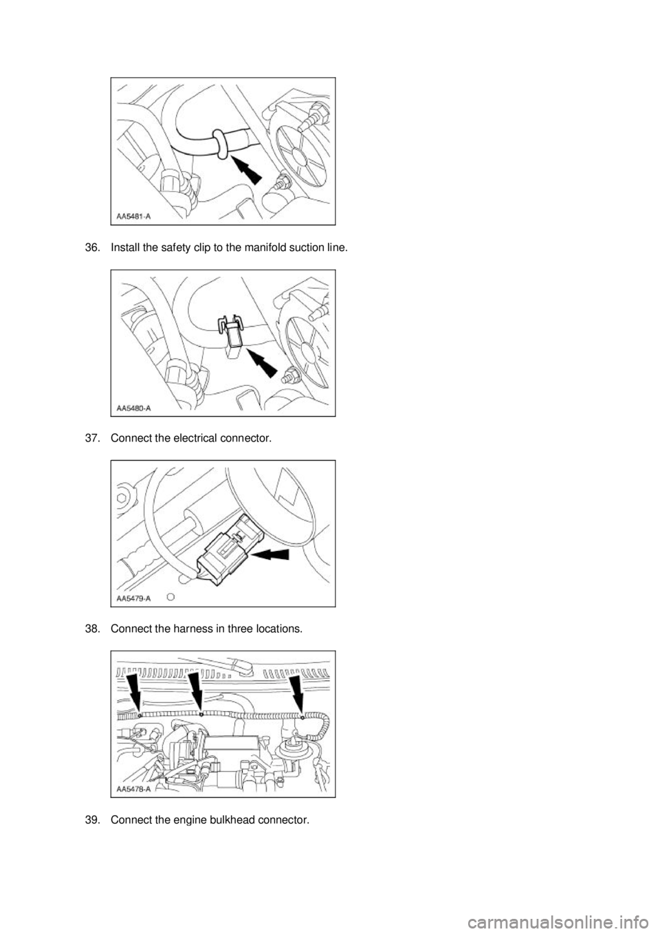
36. Install the safety clip to the manifold suction line.
37. Connect the electrical connector.
38. Connect the harness in three locations.
39. Connect the engine bulkhead connector. �K�l�j . 10 �b�a
132003 Mustang Workshop Manual
17. 11. 2011file:///C:/Ford/2000 - 2004/tsocache/SHEF_4464/S3B~us~en~ ...
 timing chain on the crankshaft sprocket, aligning the copper (marked)
link with the timing mark on the sprocket.
43. Install the LH timing c")
 timing chain on the crankshaft sprocket, aligning the copper (marked)
link with the timing mark on the sprocket.
47. Install the RH timing chain on the camshaft sprocket,")