Page 4086 of 4378

NOTE:
If a seat equipped with a seat mounted side air bag and/or a safety belt pretensioner (if
equipped) system is being serviced, the air bag system must be deactivated.
NOTE: Restraint system diagnostic tools MUST be installed under the seats in the seat side air bag (if
equipped) and safety belt pretensioner (if equipped) to floor connectors.
NOTE: Diagnostics or repairs are not to be performed on a seat equipped with a seat side air bag with
the seat in the vehicle. Prior to attempting to diagnose or repair a seat concern when equipped with a
seat side air bag, the seat must be removed from the vehicle and the restraint system diagnostic tools
must be installed in the seat side air bag electrical connectors. The restraint system diagnostic
tools must be removed prior to operating the vehicle over the road.
NOTE: After diagnosing or repairing an SRS, the restraint system diagnostic tools must be
removed before operating the vehicle over the road.
NOTE: After diagnosing or repairing a seat system, the restraint system diagnostic tools must be
removed before operating the vehicle over the road.
NOTE: The SRS must be fully operational and free of faults before releasing the vehicle to the
customer.
1. WARNING: To avoid accidental deployment and possible personal injury, the
backup power supply must be depleted before repairing or replacing any front or side air
bag supplemental restraint system (SRS) components and before servicing, replacing,
adjusting or striking components near the front or side air bag sensors, such as doors,
instrument panel, console, door latches, strikers, seats and hood latches.
Please refer to the appropriate vehicle shop manual to determine location of the front air
bag sensors.
The side air bag sensors are located at or near the base of the B- pillar.
To deplete the backup power supply energy, disconnect the battery ground cable and
wait at least one minute. Be sure to disconnect auxiliary batteries and power supplies (if
equipped).
Disconnect the battery ground cable and wait at least one minute. For additional information,
refer to Section 414 - 01 .
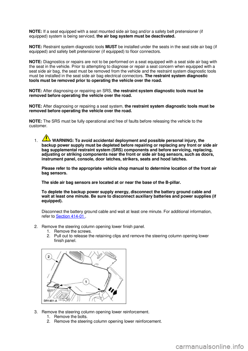
2. Remove the steering column opening lower finish panel. 1. Remove the screws.
2. Pull out to release the retaining clips and remove the steering column opening lower finish panel.
3. Remove the steering column opening lower reinforcement. 1. Remove the bolts.
2. Remove the steering column opening lower reinforcement. �K�l�j . 2 �b�a
72003 Mustang Workshop Manual
18. 11. 2011file:///C:/Ford/2000 - 2004/tsocache/SHEF_5108/S3B~us~en~ ...
Page 4090 of 4378

8. Install the steering column opening lower reinforcement.
1. Position the steering column opening lower reinforcement.
2. Install the bolts.
9. Install the steering column opening lower finish panel. 1. Align the steering column opening lower finish panel and push in, seating the retaining clips.
2. Install the screws.
10. Connect the battery ground cable. For additional information, refer to Section 414 - 01 .
11. WARNING: The restraint system diagnostic tool is for restraint system service only.
Remove from vehicle prior to road use. Failure to remove could result in injury and
possible violation of vehicle safety standards.
With all the restraint system diagnostic tools removed, prove out the supplemental restraint
system (SRS). For additional information, refer to Air Bag Supplemental Restraint System (SRS) in the Diagnosis and Testing portion of this section. �K�l�j . 6 �b�a
72003 Mustang Workshop Manual
18. 11. 2011file:///C:/Ford/2000 - 2004/tsocache/SHEF_5108/S3B~us~en~ ...
Page 4099 of 4378

and wait at least one minute. Be sure to disconnect auxiliary batteries and power
supplies (if equipped).
Disconnect the battery ground cable (14301) and wait at least one minute. For additional
information, refer to
Section 414 - 01 .
2. WARNING: To reduce the risk of serious personal injury, read and follow all
warnings, cautions, notes, and instructions in the supplemental restraint system
(SRS) deactivation/reactivation procedure.
Deactivate the supplemental restraint system (SRS). For additional information, refer to
Supplemental Restraint System (SRS) Deactivation and Reactivation in the General
Procedures portion of this section.
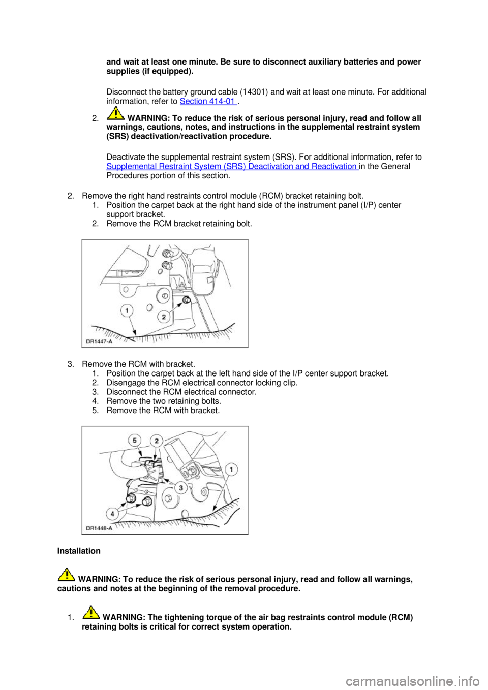
2. Remove the right hand restraints control module (RCM) bracket retaining bolt. 1. Position the carpet back at the right hand side of the instrument panel (I/P) center support bracket.
2. Remove the RCM bracket retaining bolt.
3. Remove the RCM with bracket. 1. Position the carpet back at the left hand side of the I/P center support bracket.
2. Disengage the RCM electrical connector locking clip.
3. Disconnect the RCM electrical connector.
4. Remove the two retaining bolts.
5. Remove the RCM with bracket.
Installation WARNING: To reduce the risk of serious personal injury, read and follow all warnings,
cautions and notes at the beginning of the removal procedure.
1. WARNING: The tightening torque of the air bag restraints control module (RCM) retaining bolts is critical for correct system operation. �K�l�j . 2 �b�a
42003 Mustang Workshop Manual
18. 11. 2011file:///C:/Ford/2000 - 2004/tsocache/SHEF_5108/S3B~us~en~ ...
Page 4100 of 4378

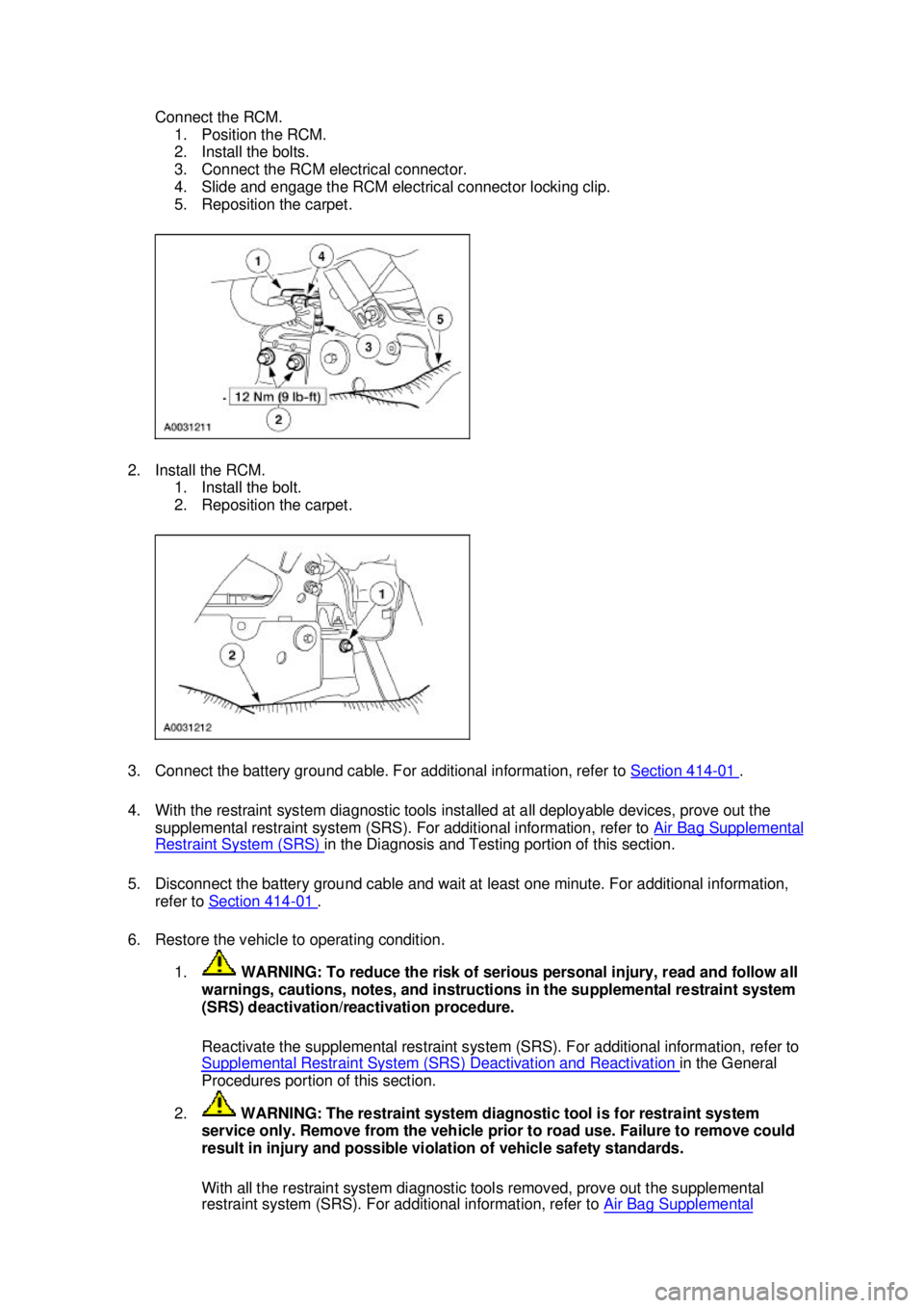
Connect the RCM.
1. Position the RCM.
2. Install the bolts.
3. Connect the RCM electrical connector.
4. Slide and engage the RCM electrical connector locking clip.
5. Reposition the carpet.
2. Install the RCM. 1. Install the bolt.
2. Reposition the carpet.
3. Connect the battery ground cable. For additional information, refer to Section 414 - 01 .
4. With the restraint system diagnostic tools installed at all deployable devices, prove out the supplemental restraint system (SRS). For additional information, refer to Air Bag Supplemental Restraint System (SRS) in the Diagnosis and Testing portion of this section.
5. Disconnect the battery ground cable and wait at least one minute. For additional information, refer to Section 414 - 01 .
6. Restore the vehicle to operating condition. 1. WARNING: To reduce the risk of serious personal injury, read and follow all
warnings, cautions, notes, and instructions in the supplemental restraint system
(SRS) deactivation/reactivation procedure.
Reactivate the supplemental restraint system (SRS). For additional information, refer to
Supplemental Restraint System (SRS) Deactivation and Reactivation in the General
Procedures portion of this section.
2. WARNING: The restraint system diagnostic tool is for restraint system
service only. Remove from the vehicle prior to road use. Failure to remove could
result in injury and possible violation of vehicle safety standards.
With all the restraint system diagnostic tools removed, prove out the supplemental
restraint system (SRS). For additional information, refer to Air Bag Supplemental �K�l�j . 3 �b�a
42003 Mustang Workshop Manual
18. 11. 2011file:///C:/Ford/2000 - 2004/tsocache/SHEF_5108/S3B~us~en~ ...
Page 4116 of 4378
13. Remove the wire harness from its holders.
14. Remove the clockspring.
1. Pry the clockspring retaining clips loose.
2. Remove the clockspring.
Installation WARNING: To reduce the risk of serious personal injury, read and follow all warnings,
cautions and notes at the beginning of the removal procedure.
Vehicles receiving a new clockspring
1. NOTE: A new clockspring is supplied in a centralized position and held there with a key.
Remove the key from the clockspring, holding the rotor in its centralized position. �zDo not allow the clockspring rotor to turn. Vehicles needing clockspring recentering �K�l�j . 5 �b�a
112003 Mustang Workshop Manual
18. 11. 2011file:///C:/Ford/2000 - 2004/tsocache/SHEF_5108/S3B~us~en~ ...