Page 3802 of 4378
9. Install the audio unit. For additional information, refer to
Section 415 - 01 .
10. If equipped, connect the shift interlock assembly to the selector lever. 1. Position the shift interlock assembly.
2. Connect the shift interlock cable.
3. Install the R- clip.
4. Install the screw.
11. Connect the ECS module electrical connector. 1. Connect the ECS module electrical connector.
2. Engage the locking tab.
12. Connect the GEM electrical connectors. �K�l�j . 10 �b�a
152003 Mustang Workshop Manual
18. 11. 2011file:///C:/Ford/2000 - 2004/tsocache/SHEF_5108/S3B~us~en~ ...
Page 3817 of 4378
REMOVAL AND INSTALLATION
Latch —
Door
Removal 1. Remove the door trim panel (23942). For additional information, refer to Section 501 - 05 .
2. Release the actuating rods by opening the clips.
3. Using a screwdriver, release the lock cylinder actuating rod.
4. Remove the door latch screws.
5. Disconnect the door ajar switch and the actuator electrical connectors.
SECTION 501-
14A: Handles, Locks, Latches and Mechanisms 2003 Mustang Workshop Manual �K�l�j . 1 �b�a
32003 Mustang Workshop Manual
18. 11. 2011file:///C:/Ford/2000 - 2004/tsocache/SHEF_5108/S3B~us~en~ ...
Page 3822 of 4378
REMOVAL AND INSTALLATION
Handle —
Exterior Door
Removal 1. Remove the door trim panel (23942). For additional information, refer to Section 501 - 05 .
2. Release the exterior door handle actuating rod by opening the clip.
3. Remove the exterior door handle nuts.
4. Remove the exterior door handle.
Installation
1. To install, reverse the removal procedure.
SECTION 501-
14A: Handles, Locks, Latches and Mechanisms 2003 Mustang Workshop Manual �K�l�j . 1 �b�a
22003 Mustang Workshop Manual
18. 11. 2011file:///C:/Ford/2000 - 2004/tsocache/SHEF_5108/S3B~us~en~ ...
Page 3824 of 4378
REMOVAL AND INSTALLATION
Handle —
Interior Door
Removal 1. Remove the door trim panel (23942). For additional information, refer to Section 501 - 05 .
2. Remove the rivet.
3. Remove the cable clip.
4. Release the cable housing from the interior handle.
5. Release the actuating cable from the interior handle and remove the handle.
SECTION 501-
14A: Handles, Locks, Latches and Mechanisms 2003 Mustang Workshop Manual �K�l�j . 1 �b�a
22003 Mustang Workshop Manual
18. 11. 2011file:///C:/Ford/2000 - 2004/tsocache/SHEF_5108/S3B~us~en~ ...
Page 3835 of 4378
REMOVAL AND INSTALLATION
Push Button Rod —
Door
Removal 1. Remove the door trim panel (23942). For additional information, refer to Section 501 - 05 .
2. Release the push button rod by opening the clip.
Installation 1. To install, reverse the removal procedure.
SECTION 501-
14A: Handles, Locks, Latches and Mechanisms 2003 Mustang Workshop Manual �K�l�j . 1 �b�a
12003 Mustang Workshop Manual
18. 11. 2011file:///C:/Ford/2000 - 2004/tsocache/SHEF_5108/S3B~us~en~ ...
Page 3839 of 4378
REMOVAL AND INSTALLATION
Switch —
Door Lock
Removal
1. CAUTION: Place a rag between the window regulator switch plate and the door trim
panel to avoid damaging the door trim panel.
Position the window regulator switch plate (14524) aside. 1. Pull at service notch.
2. Lift to release the clip at the rear edge.
2. Remove the screws and the door lock switch (14017).
Installation 1. To install, reverse the removal procedure.
SECTION 501-
14A: Handles, Locks, Latches and Mechanisms 2003 Mustang Workshop Manual �K�l�j . 1 �b�a
22003 Mustang Workshop Manual
18. 11. 2011file:///C:/Ford/2000 - 2004/tsocache/SHEF_5108/S3B~us~en~ ...
Page 3891 of 4378
REMOVAL AND INSTALLATION
Mounting Arm and Pivot Shaft
Removal
1. Park the windshield wipers in the full upright position. This will allow for easy access to the retaining clip on the wiper motor output shaft.
2. Remove the cowl top vent panels.
3. Disconnect the battery ground cable.
4. Disconnect the mounting arm and pivot shaft linkage from the wiper motor output shaft. 1. Remove the clip.
2. Disconnect the mounting arm and pivot shaft linkage from the wiper motor output shaft.
5. NOTE: It is necessary to lower the hood to remove the mounting arm and pivot shaft.
Remove the mounting arm and pivot shaft. 1. Remove the bolts.
2. Remove the mounting arm and pivot shaft through the RH cowl chamber opening.
SECTION 501-
16: Wipers and Washers 2003 Mustang Workshop Manual �K�l�j . 1 �b�a
32003 Mustang Workshop Manual
18. 11. 2011file:///C:/Ford/2000 - 2004/tsocache/SHEF_5108/S3B~us~en~ ...
Page 3892 of 4378

Installation
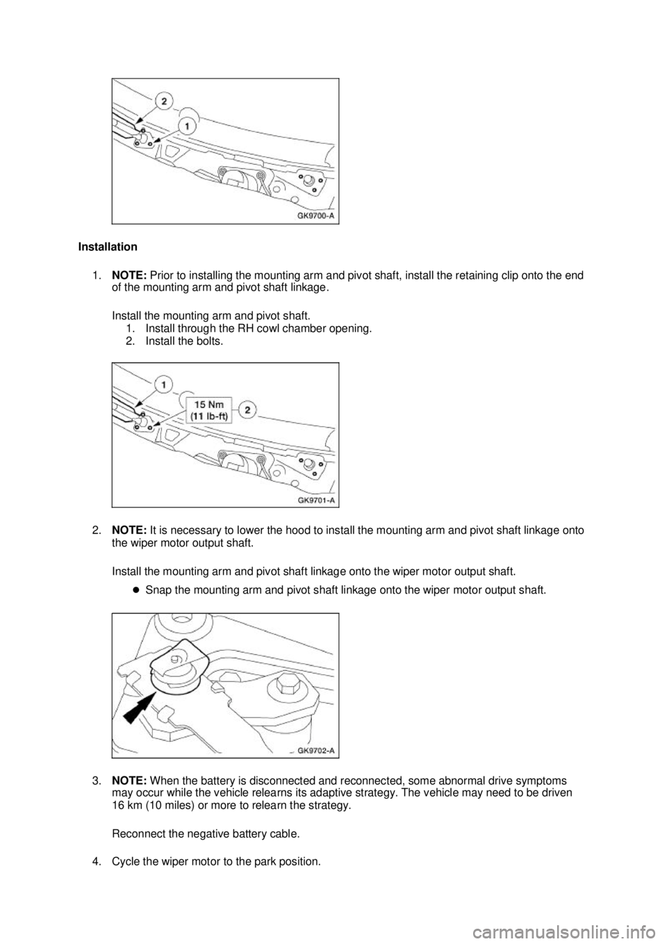
1. NOTE: Prior to installing the mounting arm and pivot shaft, install the retaining clip onto the end
of the mounting arm and pivot shaft linkage.
Install the mounting arm and pivot shaft.
1. Install through the RH cowl chamber opening.
2. Install the bolts.
2. NOTE: It is necessary to lower the hood to install the mounting arm and pivot shaft linkage onto
the wiper motor output shaft.
Install the mounting arm and pivot shaft linkage onto the wiper motor output shaft.
�zSnap the mounting arm and pivot shaft linkage onto the wiper motor output shaft.
3. NOTE: When the battery is disconnected and reconnected, some abnormal drive symptoms
may occur while the vehicle relearns its adaptive strategy. The vehicle may need to be driven
16 km (10 miles) or more to relearn the strategy.
Reconnect the negative battery cable.
4. Cycle the wiper motor to the park position. �K�l�j . 2 �b�a
32003 Mustang Workshop Manual
18. 11. 2011file:///C:/Ford/2000 - 2004/tsocache/SHEF_5108/S3B~us~en~ ...