Page 1605 of 4378

a
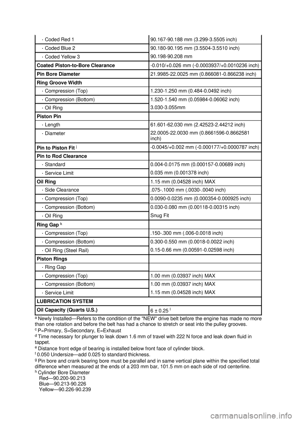
Newly Installed— Refers to the condition of the "NEW" drive belt before the engine has made no more
than one rotation and before the belt has had a chance to stretch or seat into the pulley grooves.
c P=Primary, S=Secondary, E=Exhaust
d Time necessary for plunger to leak down 1.6 mm of travel with 222 N force and leak down fluid in
tappet.
e Distance front edge of bearing is installed below front face of cylinder block.
f 0.050 Undersize— add 0.025 to standard thickness.
g Pin bore and crank bearing bore must be parallel and in same vertical plane within the specified total
difference when measured at the ends of a 203 mm bar, 101.5 mm on each side of rod centerline.
h Cylinder Bore Diameter
Red— 90.200-90.213
Blue— 90.213-90.226
Yellow— 90.226-90.239 ·
Coded Red 1 90.167-
90.188 mm (3.299- 3.5505 inch) ·
Coded Blue 2 90.180-
90.195 mm (3.5504- 3.5510 inch) ·
Coded Yellow 3 90.198-
90.208 mm Coated Piston-
to-Bore Clearance -
0.010/+0.026 mm (- 0.0003937/+0.0010236 inch) Pin Bore Diameter 21.9985-
22.0025 mm (0.866081- 0.866238 inch) Ring Groove Width
·
Compression (Top) 1.230-
1.250 mm (0.484- 0.0492 inch) ·
Compression (Bottom) 1.520-
1.540 mm (0.05984- 0.06062 inch) ·
Oil Ring 3.030-
3.055mm Piston Pin
·
Length 61.601-
62.030 mm (2.42523- 2.44212 inch) ·
Diameter 22.0005-
22.0030 mm (0.8661596- 0.8662581
inch) Pin to Piston Fit
j -
0.0045/+0.002 mm (- 0.000177/+0.0000787 inch) Pin to Rod Clearance
·
Standard 0.004-
0.0175 mm (0.000157- 0.00689 inch) ·
Service Limit 0.035 mm (0.001378 inch)
Oil Ring 1.15 mm (0.04528 inch) MAX
·
Side Clearance .075
-.1000 mm (.0030 -.0040 inch) ·
Compression (Top) 0.0090-
0.0235 mm (0.000354- 0.000925 inch) ·
Compression (Bottom) 0.030-
0.080 mm (0.00118- 0.00315 inch) ·
Oil Ring Snug Fit
Ring Gap
k ·
Compression (Top) .150
-.300 mm (.006- 0.0018 inch) ·
Compression (Bottom) 0.300-
0.550 mm (0.0018- 0.0022 inch) ·
Oil Ring (Steel Rail) 0.15-
0.66 mm (0.00591- 0.02598 inch) Piston Rings
·
Ring Gap ·
Compression (Top) 1.00 mm (0.03937 inch) MAX
·
Compression (Bottom) 1.00 mm (0.03937 inch) MAX
·
Service Limit 1.15 mm (0.04528 inch) MAX
LUBRICATION SYSTEM
Oil Capacity (Quarts U.S.)
6 ±
0.25 l �K�l�j . 4 �b�a
62003 Mustang Workshop Manual
17. 11. 2011file:///C:/Ford/2000 - 2004/tsocache/SHEF_4464/S3B~us~en~ ...
Page 1606 of 4378

i
Measured at 42 mm from piston dome, at 90 degrees to the piston pin.
j Piston pin outer diameter is larger than piston pin bore, providing a possible interference fit.
k Specification in 90.200 mm diameter gauge.
l With installation of a new filter.
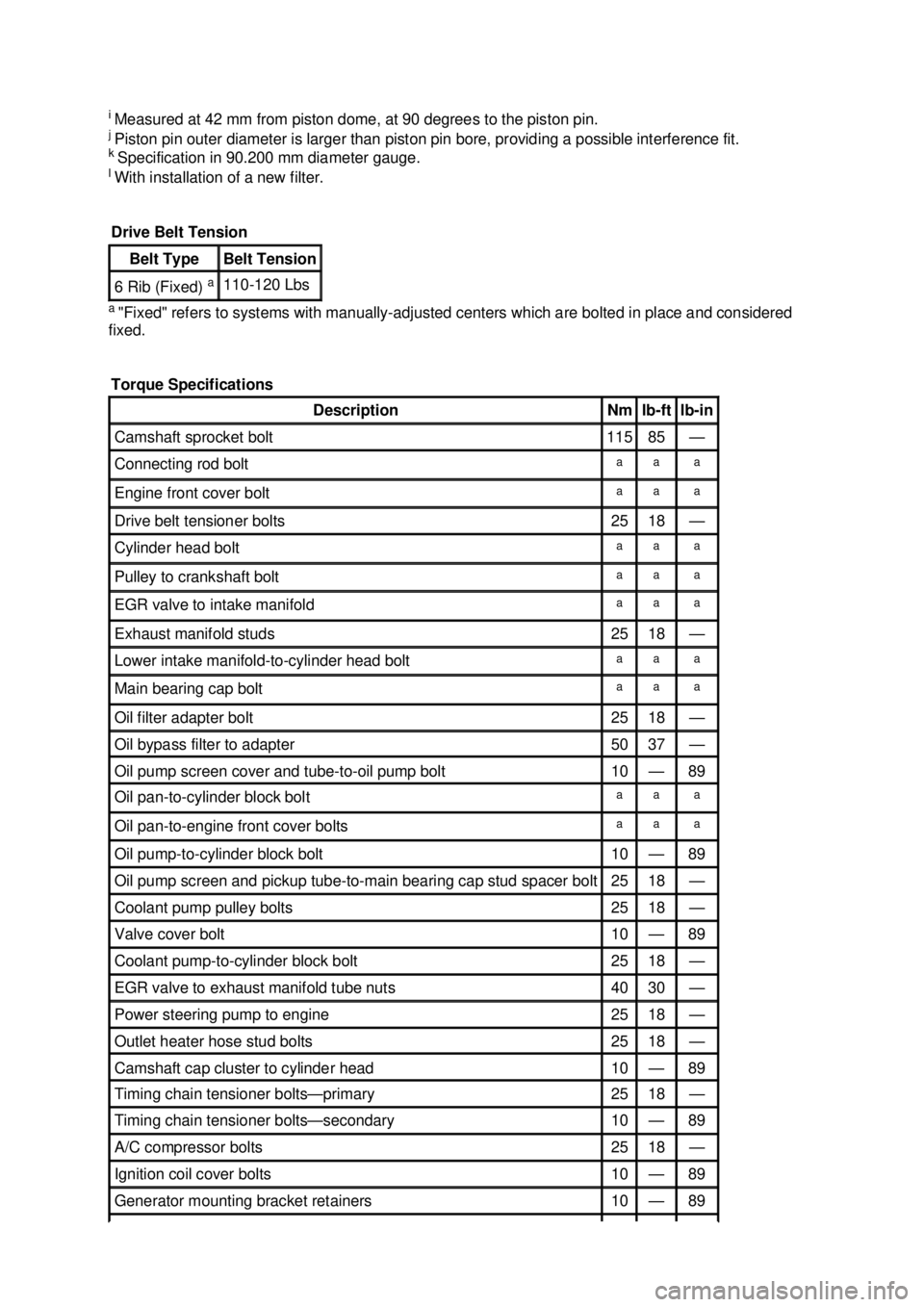
a "Fixed" refers to systems with manually- adjusted centers which are bolted in place and considered
fixed. Drive Belt Tension Belt Type Belt Tension
6 Rib (Fixed)
a 110-
120 Lbs
Torque Specifications Description Nm lb-
ft lb-
in Camshaft sprocket bolt 115 85 —
Connecting rod bolt a a a
Engine front cover bolt a a a
Drive belt tensioner bolts 25 18 —
Cylinder head bolt a a a
Pulley to crankshaft bolt a a a
EGR valve to intake manifold a a a
Exhaust manifold studs 25 18 —
Lower intake manifold-
to-cylinder head bolt a a a
Main bearing cap bolt a a a
Oil filter adapter bolt 25 18 —
Oil bypass filter to adapter 50 37 —
Oil pump screen cover and tube-
to-oil pump bolt 10 — 89
Oil pan-to-
cylinder block bolt a a a
Oil pan-to-
engine front cover bolts a a a
Oil pump-
to-cylinder block bolt 10 — 89
Oil pump screen and pickup tube-
to-main bearing cap stud spacer bolt 25 18 —
Coolant pump pulley bolts 25 18 —
Valve cover bolt 10 — 89
Coolant pump-
to-cylinder block bolt 25 18 —
EGR valve to exhaust manifold tube nuts 40 30 —
Power steering pump to engine 25 18 —
Outlet heater hose stud bolts 25 18 —
Camshaft cap cluster to cylinder head 10 — 89
Timing chain tensioner bolts—
primary 25 18 —
Timing chain tensioner bolts—
secondary 10 — 89
A/C compressor bolts 25 18 —
Ignition coil cover bolts 10 — 89
Generator mounting bracket retainers 10 — 89 �K�l�j . 5 �b�a
62003 Mustang Workshop Manual
17. 11. 2011file:///C:/Ford/2000 - 2004/tsocache/SHEF_4464/S3B~us~en~ ...
Page 1607 of 4378
a
Refer to the procedure. Flexplate bolts 80 59 —
Flywheel bolts 85 63 —
Torque converter nuts 36 27 —
Oil level indicator tube retainer 10 — 89
Primary timing chain guide-
to-engine bolts 10 — 89
Oil pump screen and pickup tube spacer to main bearing stud 25 18 —
Accelerator cable bracket 10 — 89
Belt idler pulley bolt 25 18 —
Sub-
frame brace nuts 41 30 —
Air intake scoop bolts 25 18 —
Air intake scoop bracket bolt 25 18 —
Air intake scoop bracket nuts 25 18 —
Air intake scoop bracket throttle body nut 9 — 80
Exhaust gas recirculation (EGR) vacuum regulator solenoid bolts 10 — 89 �K�l�j . 6 �b�a
62003 Mustang Workshop Manual
17. 11. 2011file:///C:/Ford/2000 - 2004/tsocache/SHEF_4464/S3B~us~en~ ...
Page 1610 of 4378

�z
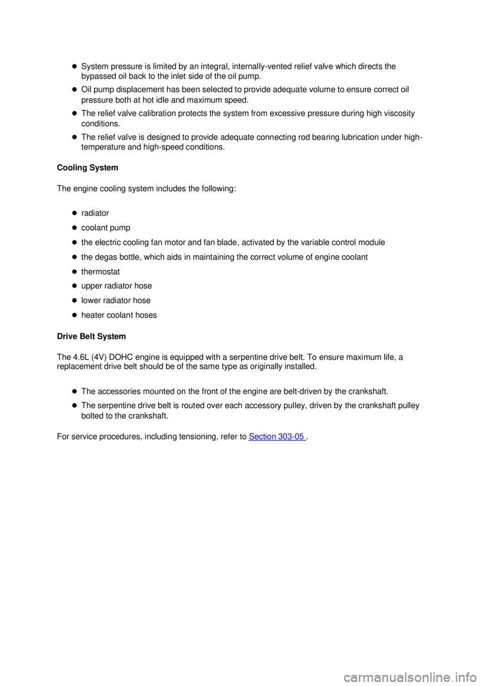
System pressure is limited by an integral, internally- vented relief valve which directs the
bypassed oil back to the inlet side of the oil pump.
�z Oil pump displacement has been selected to provide adequate volume to ensure correct oil
pressure both at hot idle and maximum speed.
�z The relief valve calibration protects the system from excessive pressure during high viscosity
conditions.
�z The relief valve is designed to provide adequate connecting rod bearing lubrication under high-
temperature and high- speed conditions.
Cooling System
The engine cooling system includes the following:
�zradiator
�z coolant pump
�z the electric cooling fan motor and fan blade, activated by the variable control module
�z the degas bottle, which aids in maintaining the correct volume of engine coolant
�z thermostat
�z upper radiator hose
�z lower radiator hose
�z heater coolant hoses
Drive Belt System
The 4.6L (4V) DOHC engine is equipped with a serpentine drive belt. To ensure maximum life, a
replacement drive belt should be of the same type as originally installed.
�zThe accessories mounted on the front of the engine are belt- driven by the crankshaft.
�z The serpentine drive belt is routed over each accessory pulley, driven by the crankshaft pulley
bolted to the crankshaft. For service procedures, including tensioning, refer to Section 303 - 05 . �K�l�j . 3 �b�a
152003 Mustang Workshop Manual
17. 11. 2011file:///C:/Ford/2000 - 2004/tsocache/SHEF_4464/S3B~us~en~ ...
Page 1616 of 4378
Item Part Number Description
1 N808102 Bolt
2 N808102 Bolt
3 19A216 Belt idler pulley
4 N806155 Bolt
5 6B288 Camshaft position sensor
6 N606543 Bolt (4 req'd)
7 6L266 Timing chain tensioner
8 W705803 Stud �K�l�j . 9 �b�a
152003 Mustang Workshop Manual
17. 11. 2011file:///C:/Ford/2000 - 2004/tsocache/SHEF_4464/S3B~us~en~ ...
Page 1617 of 4378
9 6268 Timing chain (2 req'd)
10 6K297 Timing chain guide
11 6268 Timing chain (2 req'd)
12 6M269 Timing chain tensioner
13 6L253 Timing chain tensioner arm
14 N605893 Bolt (4 req'd)
15 6K297 Timing chain guide
16 N804958 Bolt (2 req'd)
17 6L253 Timing chain tensioner arm
18 6306 Crankshaft sprocket
19 12A227 Ignition pulse ring
20 3A696 Power steering pump
21 N806176 Bolt (4 req'd)
22 3R801 Gasket
23 3A696 Power steering pump pulley
24 W706508 Stud
25 N806177 Bolt (8 req'd)
26 N808586 Stud
27 N806300 Stud (4 req'd)
28 6700 Crankshaft front seal
29 N806155 Bolt
30 6C315 Crankshaft position sensor
31 W706560 Stud
32 6C086 Engine front cover
33 N806165 Washer
34 N806139 Bolt
35 19A216 Belt Idler Pulley
36 6316 Crankshaft pulley �K�l�j . 10 �b�a
152003 Mustang Workshop Manual
17. 11. 2011file:///C:/Ford/2000 - 2004/tsocache/SHEF_4464/S3B~us~en~ ...
Page 1652 of 4378
IN-
VEHICLE REPAIR
Crankshaft Pulley
Removal 1. Remove the accessory drive belt. For additional information, refer to Section 303 - 05 .
2. Raise and support the vehicle. For additional information, refer to Section 100 - 02 .
3. Remove the bolt.
4. Using the special tool, remove the crankshaft pulley.
SECTION 303-
01D: Engine — Mach I 4.6L (4V) 2003 Mustang Workshop Manual Special Tool(s)
Remover, Crankshaft Vibration
Damper
303-
009 (T58P-6316- D) Installer, Crankshaft Vibration
Damper
303-
102 (T74P-6316- B) �K�l�j . 1 �b�a
32003 Mustang Workshop Manual
17. 11. 2011file:///C:/Ford/2000 - 2004/tsocache/SHEF_4464/S3B~us~en~ ...
Page 1653 of 4378
Installation
1. NOTE: The crankshaft pulley must be installed within four minutes after applying the silicone.
Apply silicone to the Woodruff key slot on the crankshaft pulley. �zUse Silicone Gasket and Sealant F7AZ-19554- EA or equivalent meeting Ford
specification WSE-M4G323- A4.
2. Using the special tool, install the crankshaft pulley.
3. Install the bolt and washer. Tighten the bolt in four stages. �zStage 1: Tighten the bolt to 90 Nm (66 lb- ft).
�z Stage 2: Loosen the bolt one full turn.
�z Stage 3: Tighten the bolt to 50 Nm (37 lb- ft).
�z Stage 4: Tighten the bolt an additional 90 degrees.
4. Lower the vehicle.
5. Install the accessory drive belt. For additional information, refer to Section 303 - 05 . �K�l�j . 2 �b�a
32003 Mustang Workshop Manual
17. 11. 2011file:///C:/Ford/2000 - 2004/tsocache/SHEF_4464/S3B~us~en~ ...