Page 1420 of 4378
IN-
VEHICLE REPAIR
Crankshaft Pulley
Removal 1. Remove the auxiliary crankshaft pulley. For additional information, refer to Crankshaft Pulley —
Auxiliary in this section.
2. Remove the accessory drive belt. For additional information, refer to Section 303 - 05 .
3. Remove the bolt. 4. Using the special tool, remove the crankshaft pulley. SECTION 303-
01C: Engine — Cobra 4.6L (4V) 2003 Mustang Workshop Manual Special Tool(s)
Remover, Crankshaft Vibration
Damper
303-
009 (T58P-6316- D) Installer, Crankshaft Vibration
Damper
303-
102 (T74P-6316- B)
Material Item Specification
Silicone Gasket and Sealant
F7AZ-
19554- EA WSE-
M4G323- A4 �K�l�j . 1 �b�a
32003 Mustang Workshop Manual
17. 11. 2011file:///C:/Ford/2000 - 2004/tsocache/SHEF_4464/S3B~us~en~ ...
Page 1422 of 4378
4. Install the accessory drive belt. For additional information, refer to
Section 303 - 05 .
5. Install the auxiliary crankshaft pulley. For additional information, refer to Crankshaft Pulley —
Auxiliary in this section. �K�l�j . 3 �b�a
32003 Mustang Workshop Manual
17. 11. 2011file:///C:/Ford/2000 - 2004/tsocache/SHEF_4464/S3B~us~en~ ...
Page 1423 of 4378
IN-
VEHICLE REPAIR
Crankshaft Pulley — Auxiliary
Removal and Installation 1. Remove the cooling fan. For additional information, refer to Section 303 - 03A .
2. Remove the supercharger drive belt cover.
3. Rotate the supercharger belt tensioner clockwise and remove the supercharger belt. 4. Remove the coolant hose assembly bolt. SECTION 303-
01C: Engine — Cobra 4.6L (4V) 2003 Mustang Workshop Manual Special Tool(s)
Locking Tool, Flywheel
303-
673 �K�l�j . 1 �b�a
42003 Mustang Workshop Manual
17. 11. 2011file:///C:/Ford/2000 - 2004/tsocache/SHEF_4464/S3B~us~en~ ...
Page 1435 of 4378
25. Remove the fasteners and the supercharger belt idler support bracket assembly.
26. Remove the wiring harness bracket.
27. Remove the water pump pulley.
28. Remove the bolts, the studs and the engine front cover. �K�l�j . 6 �b�a
152003 Mustang Workshop Manual
17. 11. 2011file:///C:/Ford/2000 - 2004/tsocache/SHEF_4464/S3B~us~en~ ...
Page 1438 of 4378
4. Install the wiring harness bracket and the nut.
5. Install the supercharger belt idler support bracket assembly and fasteners.
6. Install the power steering hose bracket nut.
7. Install the power steering reservoir and the fasteners. �K�l�j . 9 �b�a
152003 Mustang Workshop Manual
17. 11. 2011file:///C:/Ford/2000 - 2004/tsocache/SHEF_4464/S3B~us~en~ ...
Page 1521 of 4378
40. Remove the supercharger belt idler support bracket assembly.
41. Remove the accessory drive belt.
42. Remove the bolts and belt idler bracket.
43. Remove the bolts and the water pump pulley.
44. Remove the water pump from the cylinder block.
�zInspect and clean the sealing surfaces. �K�l�j . 12 �b�a
232003 Mustang Workshop Manual
17. 11. 2011file:///C:/Ford/2000 - 2004/tsocache/SHEF_4464/S3B~us~en~ ...
Page 1573 of 4378
65. Install the supercharger belt idler support bracket assembly.
66.
NOTE: Lubricate the O- rings with clean engine coolant.
NOTE: LH is shown, RH is similar.
Install the coolant bypass tube and mounting bolts.
67. NOTE: LH is shown, RH is similar.
Install the coolant bypass tube studs. �K�l�j . 24 �b�a
352003 Mustang Workshop Manual
17. 11. 2011file:///C:/Ford/2000 - 2004/tsocache/SHEF_4464/S3B~us~en~ ...
Page 1602 of 4378

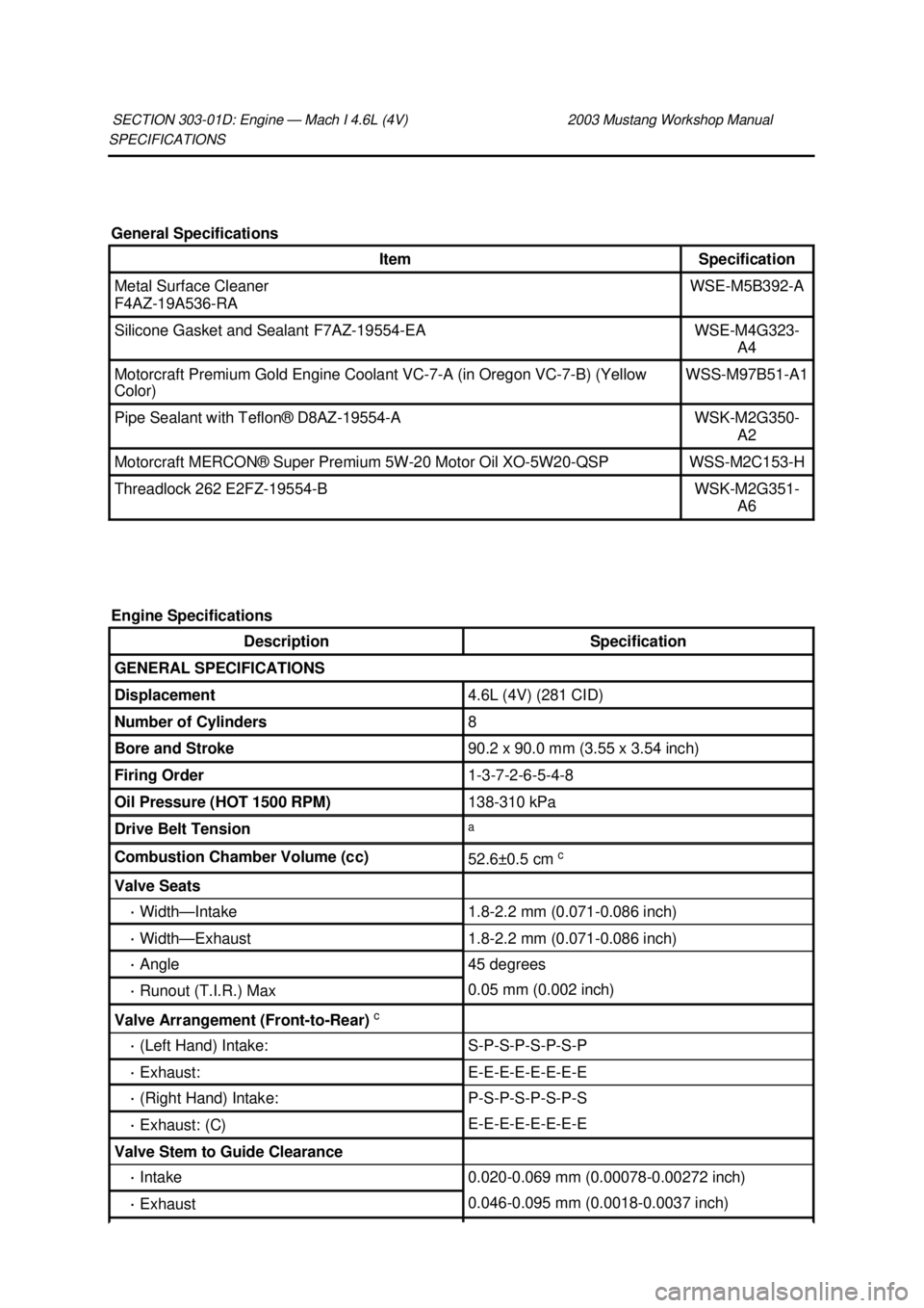
SPECIFICATIONS
SECTION 303-
01D: Engine — Mach I 4.6L (4V) 2003 Mustang Workshop Manual General Specifications
Item Specification
Metal Surface Cleaner
F4AZ-
19A536- RA WSE-
M5B392- A Silicone Gasket and Sealant F7AZ-19554-
EA WSE-
M4G323-
A4 Motorcraft Premium Gold Engine Coolant VC-7-
A (in Oregon VC-7-B) (Yellow
Color) WSS-
M97B51- A1 Pipe Sealant with Teflon® D8AZ-19554-
A WSK-
M2G350-
A2 Motorcraft MERCON® Super Premium 5W-
20 Motor Oil XO-5W20-QSP WSS-
M2C153- H Threadlock 262 E2FZ-19554-
B WSK-
M2G351-
A6
Engine Specifications Description Specification
GENERAL SPECIFICATIONS
Displacement 4.6L (4V) (281 CID)
Number of Cylinders 8
Bore and Stroke 90.2 x 90.0 mm (3.55 x 3.54 inch)
Firing Order 1-3-7-2-6-5-4-
8 Oil Pressure (HOT 1500 RPM) 138-
310 kPa Drive Belt Tension a
Combustion Chamber Volume (cc)
52.6±
0.5 cm c Valve Seats
·
Width— Intake 1.8-
2.2 mm (0.071- 0.086 inch) ·
Width— Exhaust 1.8-
2.2 mm (0.071- 0.086 inch) ·
Angle 45 degrees
·
Runout (T.I.R.) Max 0.05 mm (0.002 inch)
Valve Arrangement (Front-
to-Rear) c ·
(Left Hand) Intake: S-P-S-P-S-P-S-P
·
Exhaust: E-E-E-E-E-E-E-E
·
(Right Hand) Intake: P-S-P-S-P-S-P-S
·
Exhaust: (C) E-E-E-E-E-E-E-E
Valve Stem to Guide Clearance
·
Intake 0.020-
0.069 mm (0.00078- 0.00272 inch) ·
Exhaust 0.046-
0.095 mm (0.0018- 0.0037 inch) �K�l�j . 1 �b�a
62003 Mustang Workshop Manual
17. 11. 2011file:///C:/Ford/2000 - 2004/tsocache/SHEF_4464/S3B~us~en~ ...