2003 DODGE RAM light wiring
[x] Cancel search: light wiringPage 286 of 2895
(3) Install clutch disc, pressure plate and trans-
mission.
LINKAGE
REMOVAL
CAUTION: The hydraulic linkage has a quick dis-
connect at the slave cylinder. This fitting should
never be disconnected or tampered with. Once the
hydraulic line is connected to the slave cylinder, it
should never be disconnected.
(1) Raise and support vehicle.
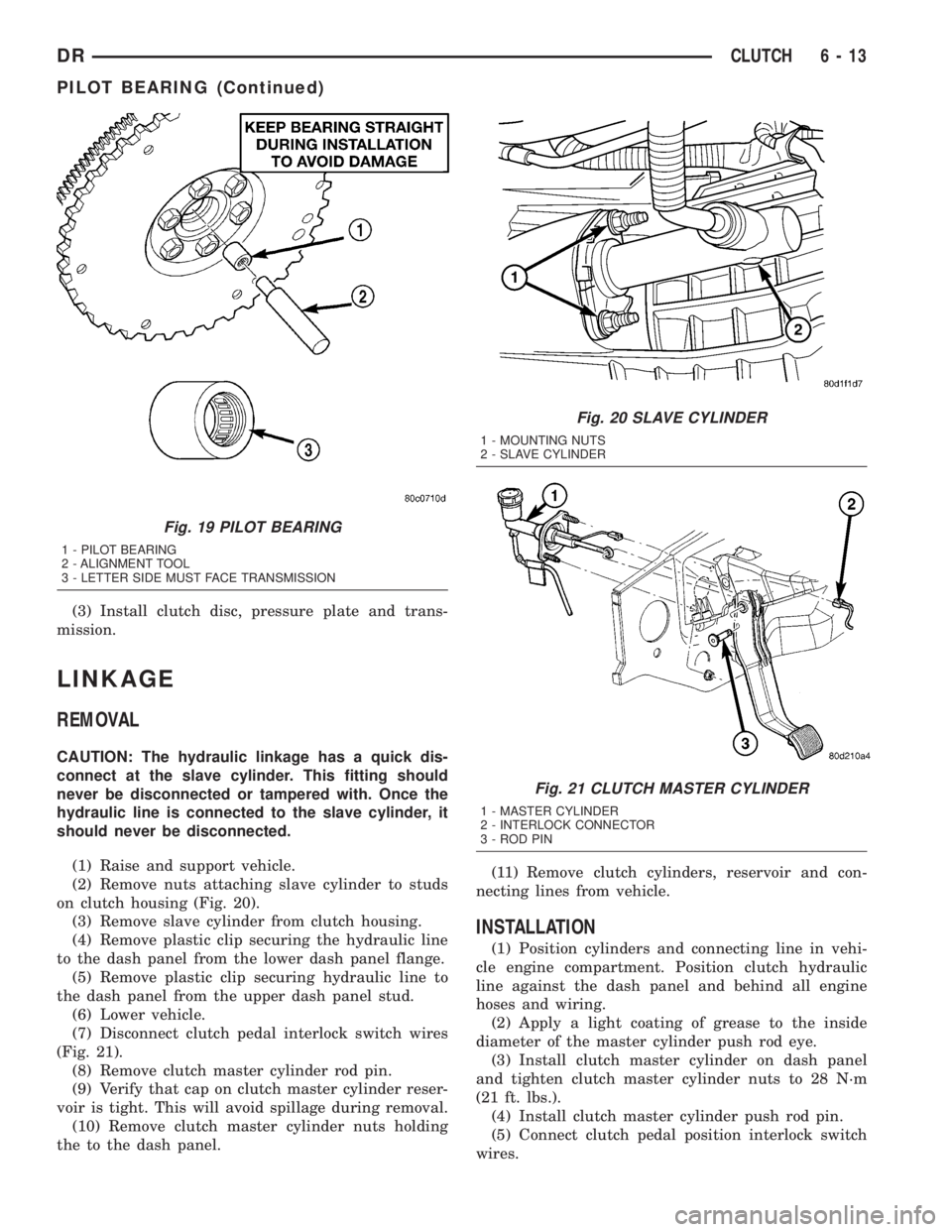
(2) Remove nuts attaching slave cylinder to studs
on clutch housing (Fig. 20).
(3) Remove slave cylinder from clutch housing.
(4) Remove plastic clip securing the hydraulic line
to the dash panel from the lower dash panel flange.
(5) Remove plastic clip securing hydraulic line to
the dash panel from the upper dash panel stud.
(6) Lower vehicle.
(7) Disconnect clutch pedal interlock switch wires
(Fig. 21).
(8) Remove clutch master cylinder rod pin.
(9) Verify that cap on clutch master cylinder reser-
voir is tight. This will avoid spillage during removal.
(10) Remove clutch master cylinder nuts holding
the to the dash panel.(11) Remove clutch cylinders, reservoir and con-
necting lines from vehicle.
INSTALLATION
(1) Position cylinders and connecting line in vehi-
cle engine compartment. Position clutch hydraulic
line against the dash panel and behind all engine
hoses and wiring.
(2) Apply a light coating of grease to the inside
diameter of the master cylinder push rod eye.
(3) Install clutch master cylinder on dash panel
and tighten clutch master cylinder nuts to 28 N´m
(21 ft. lbs.).
(4) Install clutch master cylinder push rod pin.
(5) Connect clutch pedal position interlock switch
wires.
Fig. 19 PILOT BEARING
1 - PILOT BEARING
2 - ALIGNMENT TOOL
3 - LETTER SIDE MUST FACE TRANSMISSION
Fig. 20 SLAVE CYLINDER
1 - MOUNTING NUTS
2 - SLAVE CYLINDER
Fig. 21 CLUTCH MASTER CYLINDER
1 - MASTER CYLINDER
2 - INTERLOCK CONNECTOR
3 - ROD PIN
DRCLUTCH 6 - 13
PILOT BEARING (Continued)
Page 301 of 2895

CONDITION POSSIBLE CAUSES CORRECTION
Temperature gauge reading is
inconsistent (flucttuates, cycles
or is erratic)1. During cold weather
operation, with the heater blower
in the high position, the gauge
reading may drop slightly.1. A normal condition. No correction
necessary.
2. Temperature gauge or engine
mounted gauge sensor defective
or shorted. Also, corroded or
loose wiring in this circuit.2. Check operation of gauge and repair if
necessary. (Refer to 8 - ELECTRICAL/
INSTRUMENT CLUSTER - DIAGNOSIS
AND TESTING).
3. Gauge reading rises when
vehicle is brought to a stop after
heavy use (engine still running)3. A normal condition. No correction is
necessary. Gauge should return to normal
range after vehicle is driven.
4. Gauge reading high after
re-starting a warmed up (hot)
engine.4. A normal condition. No correction is
necessary. The gauge should return to
normal range after a few minutes of
engine operation.
5. Coolant level low in radiator
(air will build up in the cooling
system causing the thermostat
to open late).5. Check and correct coolant leaks. (Refer
to 7 - COOLING - DIAGNOSIS AND
TESTING).
6. Cylinder head gasket leaking
allowing exhaust gas to enter
cooling system causing a
thermostat to open late.6. (a) Check for cylinder head gasket
leaks. (Refer to 7 - COOLING -
DIAGNOSIS AND TESTING).
(b) Check for coolant in the engine oil.
Inspect for white steam emitting from the
exhaust system. Repair as necessary.
7. Water pump impeller loose on
shaft.7. Check water pump and replace as
necessary. (Refer to 7 - COOLING/
ENGINE/WATER PUMP - REMOVAL).
8. Loose accessory drive belt.
(water pump slipping)8. (Refer to 7 - COOLING/ACCESSORY
DRIVE/DRIVE BELTS - DIAGNOSIS AND
TESTING). Check and correct as
necessary.
9. Air leak on the suction side of
the water pump allows air to
build up in cooling system
causing thermostat to open late.9. Locate leak and repair as necessary.
PRESSURE CAP IS BLOWING
OFF STEAM AND/OR
COOLANT TO COOLANT TANK.
TEMPERATURE GAUGE
READING MAY BE ABOVE
NORMAL BUT NOT HIGH.
COOLANT LEVEL MAY BE
HIGH IN COOLANT RESERVE/
OVERFLOW TANK1. Pressure relief valve in
radiator cap is defective.1. Check condition of radiator cap and cap
seals. (Refer to 7 - COOLING/ENGINE/
RADIATOR PRESSURE CAP -
DIAGNOSIS AND TESTING). Replace cap
as necessary.
COOLANT LOSS TO THE
GROUND WITHOUT
PRESSURE CAP BLOWOFF.
GAUGE READING HIGH OR
HOT1. Coolant leaks in radiator,
cooling system hoses, water
pump or engine.1. Pressure test and repair as necessary.
(Refer to 7 - COOLING - DIAGNOSIS
AND TESTING).
7 - 14 COOLINGDR
COOLING (Continued)
Page 336 of 2895
WARNING: CONSTANT TENSION HOSE CLAMPS
ARE USED ON MOST COOLING SYSTEM HOSES.
WHEN REMOVING OR INSTALLING, USE ONLY
TOOLS DESIGNED FOR SERVICING THIS TYPE OF
CLAMP. ALWAYS WEAR SAFETY GLASSES WHEN
SERVICING CONSTANT TENSION CLAMPS.
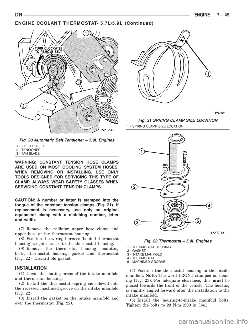
CAUTION: A number or letter is stamped into the
tongue of the constant tension clamps (Fig. 21). If
replacement is necessary, use only an original
equipment clamp with a matching number, letter
and width.
(7) Remove the radiator upper hose clamp and
upper hose at the thermostat housing.
(8) Position the wiring harness (behind thermostat
housing) to gain access to the thermostat housing.
(9) Remove the thermostat housing mounting
bolts, thermostat housing, gasket and thermostat
(Fig. 22). Discard old gasket.
INSTALLATION
(1) Clean the mating areas of the intake manifold
and thermostat housing.
(2) Install the thermostat (spring side down) into
the recessed machined groove on the intake manifold
(Fig. 22).
(3) Install the gasket on the intake manifold and
over the thermostat (Fig. 22).(4) Position the thermostat housing to the intake
manifold.Note:The word FRONT stamped on hous-
ing (Fig. 23). For adequate clearance, thismustbe
placed towards the front of the vehicle. The housing
is slightly angled forward after the installation to the
intake manifold.
(5) Install the housing-to-intake manifold bolts.
Tighten the bolts to 23 N´m (200 in. lbs.).
Fig. 20 Automatic Belt Tensioner ± 5.9L Engines
1 - IDLER PULLEY
2 - TENSIONER
3 - FAN BLADE
Fig. 21 SPRING CLAMP SIZE LOCATION
1 - SPRING CLAMP SIZE LOCATION
Fig. 22 Thermostat ± 5.9L Engines
1 - THERMOSTAT HOUSING
2 - GASKET
3 - INTAKE MANIFOLD
4 - THERMOSTAT
5 - MACHINED GROOVE
DRENGINE 7 - 49
ENGINE COOLANT THERMOSTAT- 5.7L/5.9L (Continued)
Page 347 of 2895

(6) Remove the power steering cooler mounting
bolts and position the power steering cooler out of
the way.
(7) Disconnect the transmission cooler lines at the
transmission. The transmission cooler will remain on
the radiator and can be removed as an assembly.
(8) Remove the lower shroud assembly and the
electronic viscous fan wiring from the upper shroud
assembly.
(9) Remove the two radiator upper mounting bolts
(Fig. 36).
(10) Lift radiator straight up and out of engine
compartment. The bottom of the radiator is equipped
with two alignment dowels that fit into holes in the
lower radiator support panel. Rubber biscuits (insu-
lators) are installed to these dowels. Take care not to
damage cooling fins or tubes on the radiator and air
conditioning condenser when removing.
CLEANING
Clean radiator fins are necessary for good heat
transfer. The radiator and oil cooler fins should be
cleaned when an accumulation of debris has
occurred. With the engine cold, apply cold water and
compressed air to the back (engine side) of the radi-
ator to flush the radiator and/or oil coolers of debris.
INSPECTION
Inspect the radiator side tanks for cracks, broken
or missing fittings also inspect the joint where the
tanks seam up to the radiator core for signs of leak-
age and/or deteriorating seals.
Inspect radiator core for corroded, bent or missing
cooling fins. Inspect the core for bent or damaged
cooling tubes.
INSTALLATION
(1) Install rubber insulators to alignment dowels
at lower part of radiator.
(2) Lower the radiator into position while guiding
the two alignment dowels into lower radiator sup-
port. Different alignment holes are provided in the
lower radiator support for each engine application.
(3) Install two upper radiator mounting bolts.
Tighten bolts to 11 N´m (95 in. lbs.) torque.
(4) Connect both radiator hoses and install hose
clamps.
(5) Connect transmission cooler lines to radiator
tank. Inspect quick connect fittings for debris and
install until an audible ªclickº is heard. Pull apart to
verify connection.
(6) Position power steering cooler on the radiator
and tighten nuts to 8.5M´N (75 in. lbs.)
(7) Attach electronic viscous fan wiring to upper
shroud ands install lower shroud.
(8) Position coolant recover tank hose, washer bot-
tle hose and the positive battery cable into the clips
located on the top of the radiator.
(9) Install air box and turbocharger inlet hose.
Tighten clamps to 4 N´M (35 in. lbs.).
(10) Position heater controls tofull heatposition.
(11) Fill cooling system with coolant (Refer to 7 -
COOLING - STANDARD PROCEDURE).
(12) Operate engine until it reaches normal tem-
perature. Check cooling system and automatic trans-
mission (if equipped) fluid levels.
RADIATOR PRESSURE CAP
DESCRIPTION
All cooling systems are equipped with a pressure
cap (Fig. 37). For 5.9L engines, the pressure cap is
located on top of the radiator outlet tank. For the
3.7L/4.7L engines, the pressure cap is located on top
of the coolant degas container. The cap releases pres-
sure at some point within a range of 97-to-124 kPa
(14-to-18 psi). The pressure relief point (in pounds) is
engraved on top of the cap
The cooling system will operate at pressures
slightly above atmospheric pressure. This results in a
higher coolant boiling point allowing increased radi-
ator cooling capacity. The cap contains a spring-
Fig. 36 Fan Shroud MountingÐ5.9L Diesel Engine
1 - RADIATOR SUPPORT
2 - UPPER FAN SHROUD
3 - BOLTS (2)
4 - LOWER FAN SHROUD
5 - RADIATOR
7 - 60 ENGINEDR
RADIATOR - 5.9L DIESEL (Continued)
Page 384 of 2895

²Cyclic Redundancy Check (CRC) Byte- This
byte is used to detect errors during a message trans-
mission.
²In-Frame Response (IFR) byte(s)-Ifa
response is required from the target module(s), it can
be sent during this frame. This function is described
in greater detail in the following paragraph.
The IFR consists of one or more bytes, which are
transmitted during a message. If the sending module
requires information to be received immediately, the
target module(s) can send data over the bus during
the original message. This allows the sending module
to receive time-critical information without having to
wait for the target module to access the bus. After
the IFR is received, the sending module broadcasts
an End of Frame (EOF) message and releases control
of the bus.
The PCI data bus can be monitored using the
DRBIIItscan tool. It is possible, however, for the bus
to pass all DRBIIIttests and still be faulty if the
voltage parameters are all within the specified range
and false messages are being sent.
CONTROLLER ANTILOCK
BRAKE
DESCRIPTION
The Controler Antilock Brake (CAB) is mounted to
the Hydraulic Control Unit (HCU) and operates the
ABS system (Fig. 1).
OPERATION
The CAB voltage source is through the ignition
switch in the RUN position. The CAB contains a self
check program that illuminates the ABS warning
light when a system fault is detected. Faults are
stored in a diagnostic program memory and are
accessible with the DRB III scan tool. ABS faults
remain in memory until cleared, or until after the
vehicle is started approximately 50 times. Stored
faults arenoterased if the battery is disconnected.
NOTE: If the CAB is being replaced with a new CAB
is must be reprogrammed with the use of a DRB III.
REMOVAL
(1) Remove the negative battery cable from the
battery.
(2) Pull up on the CAB harness connector release
and remove connector.
(3) Remove the CAB mounting bolts.
(4) Remove the pump connector from the CAB.
(5) Remove the CAB from the HCU.
INSTALLATION
NOTE: If the CAB is being replaced with a new CAB
is must be reprogrammed with the use of a DRB III.
(1) Install CAB to the HCU.
(2) Install the pump connector to the CAB.
(3) Install mounting bolts. Tighten to 2 N´m (16 in.
lbs.).
(4) Install the wiring harness connector to the
CAB and push down on the release to secure the con-
nector.
(5) Install negative battery cable to the battery.
DATA LINK CONNECTOR
DESCRIPTION - DATA LINK CONNECTOR
The Data Link Connector (DLC) is located at the
lower edge of the instrument panel near the steering
column.
OPERATION - DATA LINK CONNECTOR
The 16±way data link connector (diagnostic scan
tool connector) links the Diagnostic Readout Box
(DRB) scan tool or the Mopar Diagnostic System
(MDS) with the Powertrain Control Module (PCM).
Fig. 1 HYDRAULIC CONTROL UNIT
1 - HYDRAULIC CONTROL UNIT
2 - MOUNTING BOLTS
DRELECTRONIC CONTROL MODULES 8E - 3
COMMUNICATION (Continued)
Page 441 of 2895
(4) Move starter motor towards front of vehicle far
enough for nose of starter pinion housing to clear
housing. Always support starter motor during this
process. Do not let starter motor hang from wire har-
ness.
(5) Tilt nose downwards and lower starter motor
far enough to access and remove nuts securing
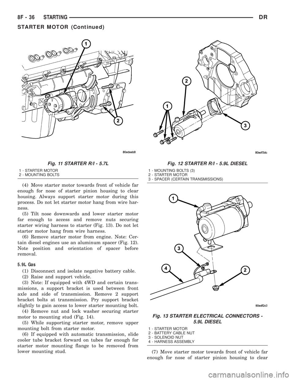
starter wiring harness to starter (Fig. 13). Do not let
starter motor hang from wire harness.
(6) Remove starter motor from engine. Note: Cer-
tain diesel engines use an aluminum spacer (Fig. 12).
Note position and orientation of spacer before
removal.
5.9L Gas
(1) Disconnect and isolate negative battery cable.
(2) Raise and support vehicle.
(3) Note: If equipped with 4WD and certain trans-
missions, a support bracket is used between front
axle and side of transmission. Remove 2 support
bracket bolts at transmission. Pry support bracket
slightly to gain access to lower starter mounting bolt.
(4) Remove nut and lock washer securing starter
motor to mounting stud (Fig. 14).
(5) While supporting starter motor, remove upper
mounting bolt from starter motor.
(6) If equipped with automatic transmission, slide
cooler tube bracket forward on tubes far enough for
starter motor mounting flange to be removed from
lower mounting stud.
(7) Move starter motor towards front of vehicle far
enough for nose of starter pinion housing to clear
Fig. 11 STARTER R/I - 5.7L
1 - STARTER MOTOR
2 - MOUNTING BOLTS
Fig. 12 STARTER R/I - 5.9L DIESEL
1 - MOUNTING BOLTS (3)
2 - STARTER MOTOR
3 - SPACER (CERTAIN TRANSMISSIONS)
Fig. 13 STARTER ELECTRICAL CONNECTORS -
5.9L DIESEL
1 - STARTER MOTOR
2 - BATTERY CABLE NUT
3 - SOLENOID NUT
4 - HARNESS ASSEMBLY
8F - 36 STARTINGDR
STARTER MOTOR (Continued)
Page 448 of 2895

HEATED SEAT SYSTEM
TABLE OF CONTENTS
page page
HEATED SEAT SYSTEM
DESCRIPTION..........................3
OPERATION............................4
DIAGNOSIS AND TESTING - HEATED SEAT
SYSTEM.............................4
HEATED SEAT ELEMENT
DESCRIPTION..........................5
OPERATION............................6
DIAGNOSIS AND TESTING - HEATED SEAT
ELEMENT............................6
REMOVAL.............................6
INSTALLATION..........................6
HEATED SEAT SENSOR
DESCRIPTION..........................7OPERATION............................7
DIAGNOSIS AND TESTING - HEATED SEAT
SENSOR.............................7
REMOVAL.............................7
HEATED SEAT SWITCH
DESCRIPTION..........................7
OPERATION............................8
DIAGNOSIS AND TESTING - HEATED SEAT
SWITCH.............................8
REMOVAL.............................9
INSTALLATION..........................9
HEATED SEAT SYSTEM
DESCRIPTION
Individually controlled, electrically heated front
seats are available as a factory-installed option on
some DR models. Vehicles with this option can be
visually identified by the leather trim seats and two
separate heated seat switches mounted in the lower
center of the instrument panel. The heated seat sys-
tem allows the front seat driver and passenger to
select from two different levels of electrical seat heat-
ing, or no seat heating to suit their individual com-
fort requirements. The heated seat system for this
vehicle includes the following major components,
which are described in further detail later in this sec-
tion:
²Heated Seat Switches- Two heated seat
switches are used per vehicle. One switch is used for
each front seat. The switches are mounted in the
instrument panel, below the radio (Fig. 1). Each
switch also includes two Light-Emitting Diode (LED)
indicator lamps and an incandescent back lighting
bulb.
²Heated Seat Module- also referred to as the
Seat Heat Interface Module (SHIM), this module con-
tains the solid state electronic control and diagnostic
logic circuitry for the heated seat system. One heated
seat module is used per vehicle and is mounted
under the drivers front seat cushion (Fig. 1). Refer to
the Electronic Control Modules section of the service
manual for additional heated seat module informa-
tion.²Heated Seat Elements- Four heated seat ele-
ments are used per vehicle. One element is used for
each front seat back and one element and sensor
assembly is used for each front seat cushion (Fig. 1).
The heating elements are integral to the individual
front seat and seat back cushions and cannot be
removed once installed at the factory. Replacement
seat heating elements are available, without having
to replace the entire seat cushion or trim cover. Refer
to the detailed procedure later in this section.
²Heated Seat Sensors- Two heated seat sen-
sors are used per vehicle. One heated seat tempera-
ture sensor is used for each front seat cushion. The
sensors are integral to the individual front seat cush-
ion heating elements (Fig. 1) and cannot be removed
once installed at the factory. Replacement seat heat-
ing elements with the sensors are available, without
having to replace the entire seat cushion or trim
cover. Refer to the detailed procedure later in this
section.
Following are general descriptions and operations
of the major components in the heated seat system.
See the owner's manual in the vehicle glove box for
more information on the features, use and operation
of the heated seat system. Refer toWiringfor the
location of complete heated seat system wiring dia-
grams.
DRHEATED SEAT SYSTEM 8G - 3
Page 450 of 2895

Diagnostic logic is built into the heated seat mod-
ule to help the person trying to locate the problem by
the most efficient means possible. Anytime a problem
is suspected, locate the diagnosis and testing proce-
dure for the component in question and follow the
steps until the specific problem is located and
resolved. Once the problem is thought to be cor-
rected, verify correct system operation. If the heated
seat system is functioning correctly return the vehi-
cle to service.
If a problem could not be verified such as not find-
ing anything wrong when following the diagnostic
procedure, this is a good indication that a INTER-
MITTENT problem may be present. You must then
attempt to find the intermittent problem, such as
moving the heating element within the seat while
testing continuity or wiggling the wire harness's/elec-
trical connectors under the seat while testing conti-
nuity. Always, eliminate all other potential problems
before attempting to replace the heated seat module.
PRELIMINARY TEST
Refer toWiringfor the location of complete heated
seat system wiring diagrams. Before testing the indi-
vidual components in the heated seat system, per-
form the following preliminary checks:
WARNING: DISABLE THE AIRBAG SYSTEM
BEFORE ATTEMPTING ANY STEERING WHEEL,
STEERING COLUMN, OR INSTRUMENT PANEL
COMPONENT DIAGNOSIS OR SERVICE. DISCON-
NECT AND ISOLATE THE BATTERY NEGATIVE
CABLE, THEN WAIT TWO MINUTES FOR THE AIR-
BAG SYSTEM CAPACITOR TO DISCHARGE
BEFORE PERFORMING FURTHER DIAGNOSIS OR
SERVICE. THIS IS THE ONLY SURE WAY TO DIS-
ABLE THE AIRBAG SYSTEM. FAILURE TO TAKE
THE PROPER PRECAUTIONS COULD RESULT IN
ACCIDENTAL AIRBAG DEPLOYMENT AND POSSI-
BLE PERSONAL INJURY.
²If the heated seat switch back lighting and the
cluster illumination lamps do not illuminate with the
headlamps or park lamps turned On, refer to the
Instrument Clustersection of the service manual
for the location of cluster illumination lamp diagnosis
and testing procedures. If the heated seat switch
back lighting does not illuminate, but the cluster illu-
mination lamps do illuminate with the headlamps or
park lamps turned On, refer toDiagnosis and Test-
ing the Heated Seat Switchin this section for the
location of the heated seat switch diagnosis and test-
ing procedures.
²If a single LED indicator lamp for one heated
seat switch does not operate and the heated seat ele-
ments do heat, refer toDiagnosis and Testing theHeated Seat Switchin this section for heated seat
switch diagnosis and testing procedures.
²If both LED indicator lamps for a heated seat
switch operate, but the heated seat elements do not
heat, refer toDiagnosis and Testing the Heated
Seat Modulein Electronic Control Modules for
heated seat module diagnosis and testing procedures.
²If the indicator lamp on either heated seat
switch remains illuminated after the heated seat has
been turned Off, refer toDiagnosis and Testing
the Heated Seat Modulein Electronic Control
Modules for heated seat module diagnosis and test-
ing procedures.
HEATED SEAT ELEMENT
DESCRIPTION
Vehicles equipped with the optional heated seat
system have two sets of electrically operated heating
element grids located in each front seat, one set for
the seat cushion and the other set for the seat back.
Each of the heated seat element grids consists of a
single length of resistor wire that is routed in a zig-
zag pattern and captured between a covering and the
adhesive foam rubber backing. Short pigtail wires
with connectors (Fig. 2) are soldered to each end of
each resistor wire element grid, which connect all of
Fig. 2 Heating Element Installed on Seat Cushion
Foam
1 - SEAT BACK WIRE HARNESS
2 - HEATED SEAT WIRE HARNESS CONNECTOR
3 - HEATED SEAT CUSHION ELEMENT
DRHEATED SEAT SYSTEM 8G - 5
HEATED SEAT SYSTEM (Continued)