INSTALLATION
WARNING: BEFORE SERVICING THE STEERING
COLUMN THE AIRBAG SYSTEM MUST BE DIS-
ARMED. REFER TO ELECTRICAL RESTRAINT SYS-
TEM FOR SERVICE PROCEDURES. FAILURE TO DO
SO MAY RESULT IN ACCIDENTAL DEPLOYMENT OF
THE AIRBAG AND POSSIBLE PERSONAL INJURY.
CAUTION: All fasteners must be torqued to specifi-
cation to ensure proper operation of the steering
column.
(1) Position the steering column on the dash panel
support and loosely install the mounting nuts.
(2) Firmly slide the steering column upward
against the studs in dash panel and hand tighten the
nuts.
(3) Install the steering shaft coupler on the steer-
ing shaft and loosely install anewbolt.
(4) Center steering column in dash opening and
tighten mounting nuts to 28 N´m (250 in. lbs.).
NOTE: Torque the upper left nut first then the lower
right nut. Then torque the lower left nut then the
upper right nut.
NOTE: A new bolt must be used for reinstallation.
(5) Tighten the coupler bolt to 57 N´m (42 ft. lbs.).
(6) Install a new brake light switch (Refer to 8 -
ELECTRICAL/LAMPS/LIGHTING - EXTERIOR/
BRAKE LAMP SWITCH - REMOVAL).(7) Install the shifter cable. (Refer to 21 - TRANS-
MISSION/TRANSAXLE/AUTOMATIC - 32RH/GEAR
SHIFT CABLE - INSTALLATION)
(8) Connect the wiring harness to the column.
(9) Install the SKIM module.
(10) Install the clockspring(Refer to 8 - ELECTRI-
CAL/RESTRAINTS/CLOCKSPRING - REMOVAL).
(11) Install the shrouds.
(12) Install the steering column opening cover
(Refer to 23 - BODY/INSTRUMENT PANEL/STEER-
ING COLUMN OPENING COVER - INSTALLA-
TION).
(13) Align the spline on the wheel hub to shaft.
(14) Then install the steering wheel and install a
newbolt. Tighten the bolt to 61 N´m (45 ft. lbs.).
(15) Install the airbag (Refer to 8 - ELECTRICAL/
RESTRAINTS/DRIVER AIRBAG - INSTALLATION).
(16) Install the two steering wheel switches.
(17) Install the tilt lever handle.
(18) Install the negative battery terminal.
(19) Test the operation of the horn, Electronic
PRNDL Indicator, lights and any other functions that
are steering column operated.IGNITION SWITCH
DESCRIPTION
The ignition switch is located on the steering col-
umn. It is used as the main on/off switching device
for most electrical components. The mechanical key
cylinder is used to engage/disengage the electrical
ignition switch.
OPERATION
Vehicles equipped with an automatic trans-
mission and a steering column mounted shifter:
an interlock device is located within the shift cable.
This interlock device is used to lock the transmission
shifter in the PARK position when the key cylinder is
in any position and the brake pedal is not depressed.
DIAGNOSIS AND TESTING - IGNITION SWITCH
TEST AND REPAIR
If the key removal effort is excessive on a vehicle
with a automatic transmission first adjust the shift
linkage, (Refer to 21 - TRANSMISSION/TRANS-
AXLE/AUTOMATIC - 46RE/GEAR SHIFT CABLE -
ADJUSTMENTS).
If the ignition switch effort is excessive remove the
ignition key cylinder from the steering column. (Refer
to 19 - STEERING/COLUMN/LOCK CYLINDER
HOUSING - REMOVAL). Check the turning effort of
the key cylinder. If the ignition key cylinder effort is
excessive replace the key cylinder.
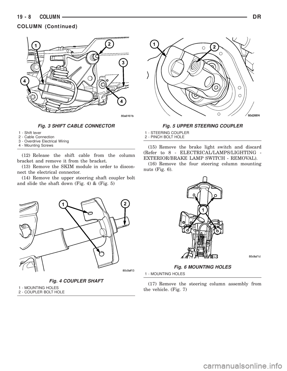
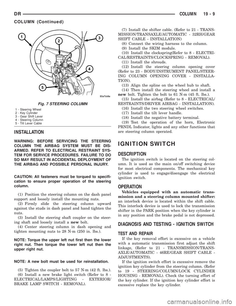
Fig. 7 STEERING COLUMN
1 - Steering Wheel
2 - Key Cylinder
3 - Gear Shift Lever
4 - Steering Column
5 - Tilt Lever Cable
DRCOLUMN 19 - 9
COLUMN (Continued)
OVERDRIVE SWITCH
DESCRIPTION
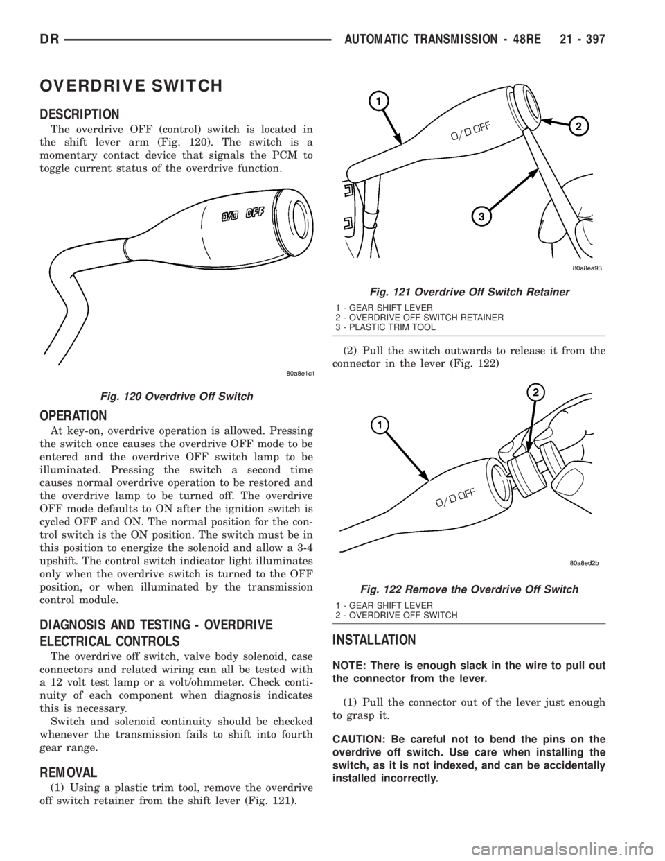
The overdrive OFF (control) switch is located in
the shift lever arm (Fig. 120). The switch is a
momentary contact device that signals the PCM to
toggle current status of the overdrive function.
OPERATION
At key-on, overdrive operation is allowed. Pressing
the switch once causes the overdrive OFF mode to be
entered and the overdrive OFF switch lamp to be
illuminated. Pressing the switch a second time
causes normal overdrive operation to be restored and
the overdrive lamp to be turned off. The overdrive
OFF mode defaults to ON after the ignition switch is
cycled OFF and ON. The normal position for the con-
trol switch is the ON position. The switch must be in
this position to energize the solenoid and allow a 3-4
upshift. The control switch indicator light illuminates
only when the overdrive switch is turned to the OFF
position, or when illuminated by the transmission
control module.
DIAGNOSIS AND TESTING - OVERDRIVE
ELECTRICAL CONTROLS
The overdrive off switch, valve body solenoid, case
connectors and related wiring can all be tested with
a 12 volt test lamp or a volt/ohmmeter. Check conti-
nuity of each component when diagnosis indicates
this is necessary.
Switch and solenoid continuity should be checked
whenever the transmission fails to shift into fourth
gear range.
REMOVAL
(1) Using a plastic trim tool, remove the overdrive
off switch retainer from the shift lever (Fig. 121).(2) Pull the switch outwards to release it from the
connector in the lever (Fig. 122)
INSTALLATION
NOTE: There is enough slack in the wire to pull out
the connector from the lever.
(1) Pull the connector out of the lever just enough
to grasp it.
CAUTION: Be careful not to bend the pins on the
overdrive off switch. Use care when installing the
switch, as it is not indexed, and can be accidentally
installed incorrectly.
Fig. 120 Overdrive Off Switch
Fig. 121 Overdrive Off Switch Retainer
1 - GEAR SHIFT LEVER
2 - OVERDRIVE OFF SWITCH RETAINER
3 - PLASTIC TRIM TOOL
Fig. 122 Remove the Overdrive Off Switch
1 - GEAR SHIFT LEVER
2 - OVERDRIVE OFF SWITCH
DRAUTOMATIC TRANSMISSION - 48RE 21 - 397
Adhesion Promoter/Surface Modifier:
Adhesion Promoters/Surface Modifiers are required
for certain plastics. All three categories may have
plastics that require the use of adhesion promoter/
surface modifiers. Always follow repair material man-
ufacturer's plastic identification and repair
procedures.
SAFETY PRECAUTION AND WARNINGS
WARNING:
²EYE PROTECTION SHOULD BE USED WHEN
SERVICING COMPONENTS. PERSONAL INJURY
CAN RESULT.
²USE AN OSHA APPROVED BREATHING MASK
WHEN MIXING EPOXY, GRINDING, AND SPRAYING
PAINT OR SOLVENTS IN A CONFINED AREA. PER-
SONAL INJURY CAN RESULT.²AVOID PROLONGED SKIN CONTACT WITH
RESIN, PETROLEUM, OR ALCOHOL BASED SOL-
VENTS. PERSONAL INJURY CAN RESULT.
²DO NOT VENTURE UNDER A HOISTED VEHI-
CLE THAT IS NOT PROPERLY SUPPORTED ON
SAFETY STANDS. PERSONAL INJURY CAN
RESULT.
NOTE:
²When holes must be drilled or cut in body pan-
els, verify locations of internal body components
and electrical wiring. Damage to vehicle can result.
²Do not use abrasive chemicals or compounds
on undamaged painted surfaces around repair
areas. Damage to finish can result.
RIGID, SEMI-RIGID, AND FLEXIBLE PLASTIC PARTS TYPES
CODE FAMILY NAME COMMON TRADE NAME TYPICAL APPLICATION
ASA ACRYLONITRILE STYRENE
ACRYLITELURAN S CONSOLES, GRILLES
ABS ACRYLONITRILE
BUTADIENE STYRENETERLURAN9A9PILLARS, CONSOLES,
GRILLES
ABS/PC ABS/PC ALLOY PULSE, PROLOY,
BAYBLENDDOORS, INSTRUMENT
PANELS
ABS/PVC ABS/PV ALLOY PROLOY, PULSE, LUSTRAN,
CYCLOVINDOOR PANELS, GRILLES,
TRIM
BMC BULK MOLDING
COMPOUNDBMC FENDER EXTENSIONS
EMA EHTYLENE METHYL
ACRYLATE/IONOMERSURLYN, EMA, IONOMER BUMPER GUARDS, PADS
METTON METTON METTON GRILLES, KICK PANELS,
RUNNING BOARDS
MPPO MODIFIED
POLYPHENYLENE OXIDEMPPO SPOILER ASSEMBLY
PA POLYAMID ZYTEL, VYDYNE, PA,
MINLONFENDERS, QUARTER PANELS
PET THERMOPLASTIC
POLYESTERRYNITE TRIM
PBT/PPO PBT/PPO ALLOY GERMAX CLADDINGS
PBTP POLYBUTYLENE
THEREPTHALATEPBT, PBTP, POCAN, VALOX WHEEL COVERS, FENDERS,
GRILLES
PBTP/EEBC POLYBUTYLENE
THEREPTHALATE/EEBC
ALLOYBEXLOY,9M9, PBTP/EEBC FASCIAS, ROCKER PANEL,
MOLDINGS
PC POLYCARBONATE LEXAN, MERLON, CALIBRE,
MAKROLON PCTAIL LIGHT LENSES, IP TRIM,
VALANCE PANELS
23 - 4 BODYDR
BODY (Continued)