2003 DODGE RAM Head torque
[x] Cancel search: Head torquePage 34 of 2895

angle while adjusting caster, move one pivot bolt of
the upper control arm in or out. Then move the other
pivot bolt of the upper control arm in the opposite
direction. Install special tool 8876 between the top of
the upper control arm bracket and the upper control
arm (on 1500 series 4X2 & 4X4). Install special tool
8876 between the bottom of the upper control arm
bracket pressing the tool against the frame and the
upper control arm (on 2500/3500 series 4X2) in order
to move the upper control arm outwards for proper
adjustment with the vehicle at normal ride height
(Fig. 3).
To increase positive caster angle, move the rear
position of the upper control arm inward (toward the
engine). Move the front of the upper control arm out-
ward (away from the engine) slightly until the origi-
nal camber angle is obtained using special tool 8876
to move the upper control arm for proper adjustment.
(Fig. 3)
CAMBER
Move both pivot bolts of the upper control arm
together in or out. This will change the camber angle
significantly and little effect on the caster angle
using special tool 8876 to move the upper control
arm for proper adjustment. (Fig. 3)
After adjustment is made tighten the upper control
arm nuts to proper torque specification.
TOE ADJUSTMENT
The wheel toe position adjustment is the final
adjustment.
(1) Start the engine and turn wheels both ways
before straightening the wheels. Secure the steering
wheel with the front wheels in the straight-ahead
position.
(2) Loosen the tie rod jam nuts.
NOTE: Each front wheel should be adjusted for
one-half of the total toe position specification. This
will ensure the steering wheel will be centered
when the wheels are positioned straight-ahead.
(3) Adjust the wheel toe position by turning the
inner tie rod as necessary (Fig. 4).
(4) Tighten the tie rod jam nut to 75 N´m (55 ft.
lbs.).
(5) Verify the specifications
(6) Turn off engine.
STANDARD PROCEDURE - ALIGNMENT
LINK/COIL SUSPENSION
Before each alignment reading the vehicle should
be jounced (rear first, then front). Grasp each
bumper at the center and jounce the vehicle up and
down several times. Always release the bumper inthe down position.Set the front end alignment to
specifications while the vehicle is in its NOR-
MALLY LOADED CONDITION.
CAMBER:The wheel camber angle is preset and
is not adjustable.
CASTER:Check the caster of the front axle for
correct angle. Be sure the axle is not bent or twisted.
Road test the vehicle and make left and right turn.
Observe the steering wheel return-to-center position.
Low caster will cause poor steering wheel returnabil-
ity.
Caster can be adjusted by rotating the cams on the
lower suspension arm (Fig. 5).
TOE POSITION:The wheel toe position adjust-
ment should be the final adjustment.
Fig. 4 TIE ROD END
1 - JAM NUT
2 - TIE ROD - INNER
3 - TIE ROD END - OUTER
Fig. 5 ALIGNMENT ADJUSTMENT CAM
1 - BRACKET REINFORCEMENT
2 - ADJUSTING BOLT
3 - ADJUSTMENT CAM
DRWHEEL ALIGNMENT 2 - 5
WHEEL ALIGNMENT (Continued)
Page 99 of 2895
(6) Install the marked bearing caps in their correct
positions. Install and snug the bolts.
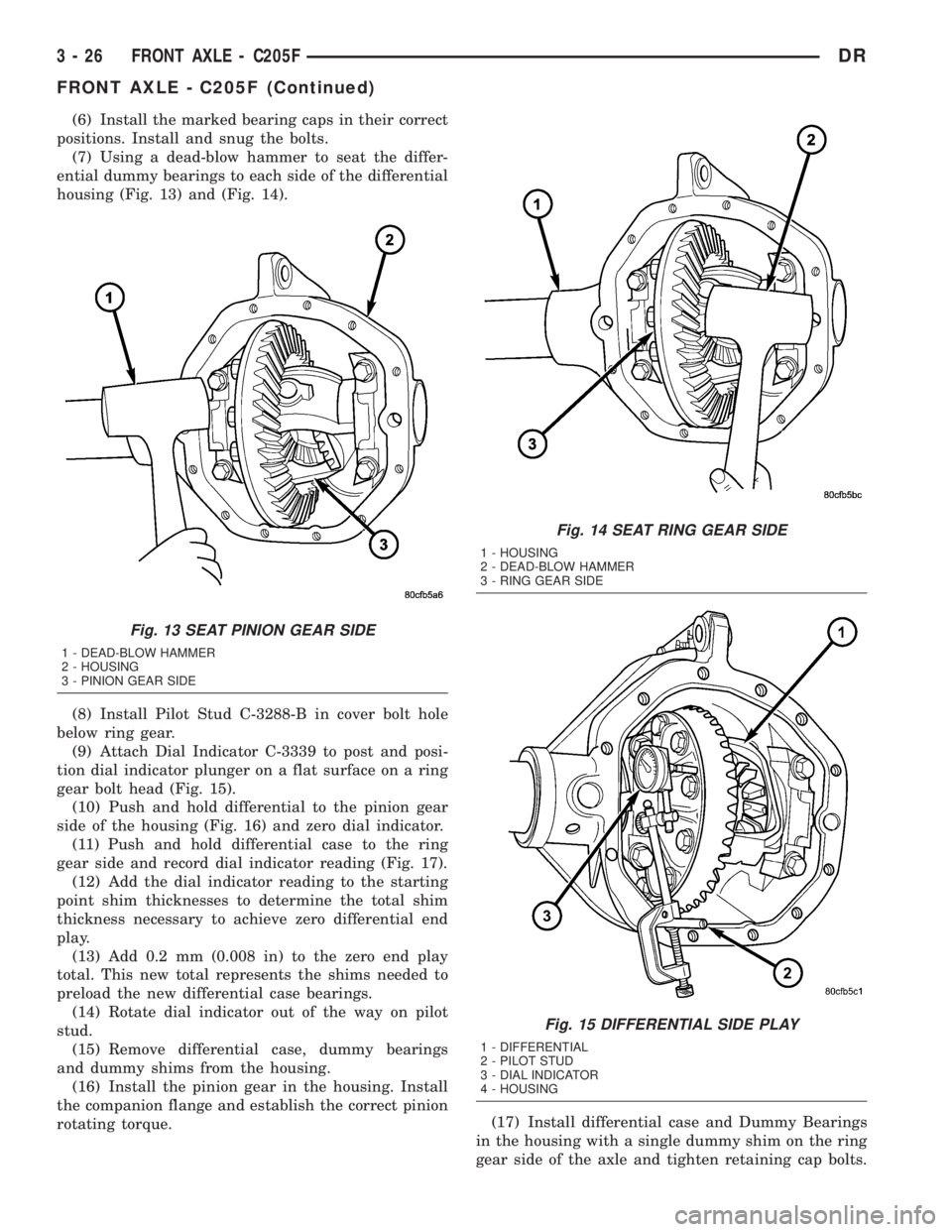
(7) Using a dead-blow hammer to seat the differ-
ential dummy bearings to each side of the differential
housing (Fig. 13) and (Fig. 14).
(8) Install Pilot Stud C-3288-B in cover bolt hole
below ring gear.
(9) Attach Dial Indicator C-3339 to post and posi-
tion dial indicator plunger on a flat surface on a ring
gear bolt head (Fig. 15).
(10) Push and hold differential to the pinion gear
side of the housing (Fig. 16) and zero dial indicator.
(11) Push and hold differential case to the ring
gear side and record dial indicator reading (Fig. 17).
(12) Add the dial indicator reading to the starting
point shim thicknesses to determine the total shim
thickness necessary to achieve zero differential end
play.
(13) Add 0.2 mm (0.008 in) to the zero end play
total. This new total represents the shims needed to
preload the new differential case bearings.
(14) Rotate dial indicator out of the way on pilot
stud.
(15) Remove differential case, dummy bearings
and dummy shims from the housing.
(16) Install the pinion gear in the housing. Install
the companion flange and establish the correct pinion
rotating torque.(17) Install differential case and Dummy Bearings
in the housing with a single dummy shim on the ring
gear side of the axle and tighten retaining cap bolts.
Fig. 13 SEAT PINION GEAR SIDE
1 - DEAD-BLOW HAMMER
2 - HOUSING
3 - PINION GEAR SIDE
Fig. 14 SEAT RING GEAR SIDE
1 - HOUSING
2 - DEAD-BLOW HAMMER
3 - RING GEAR SIDE
Fig. 15 DIFFERENTIAL SIDE PLAY
1 - DIFFERENTIAL
2 - PILOT STUD
3 - DIAL INDICATOR
4 - HOUSING
3 - 26 FRONT AXLE - C205FDR
FRONT AXLE - C205F (Continued)
Page 109 of 2895
CAUTION: Never loosen pinion nut to decrease pin-
ion bearing rotating torque and never exceed spec-
ified preload torque. If preload torque or rotating
torque is exceeded a new collapsible spacer must
be installed.
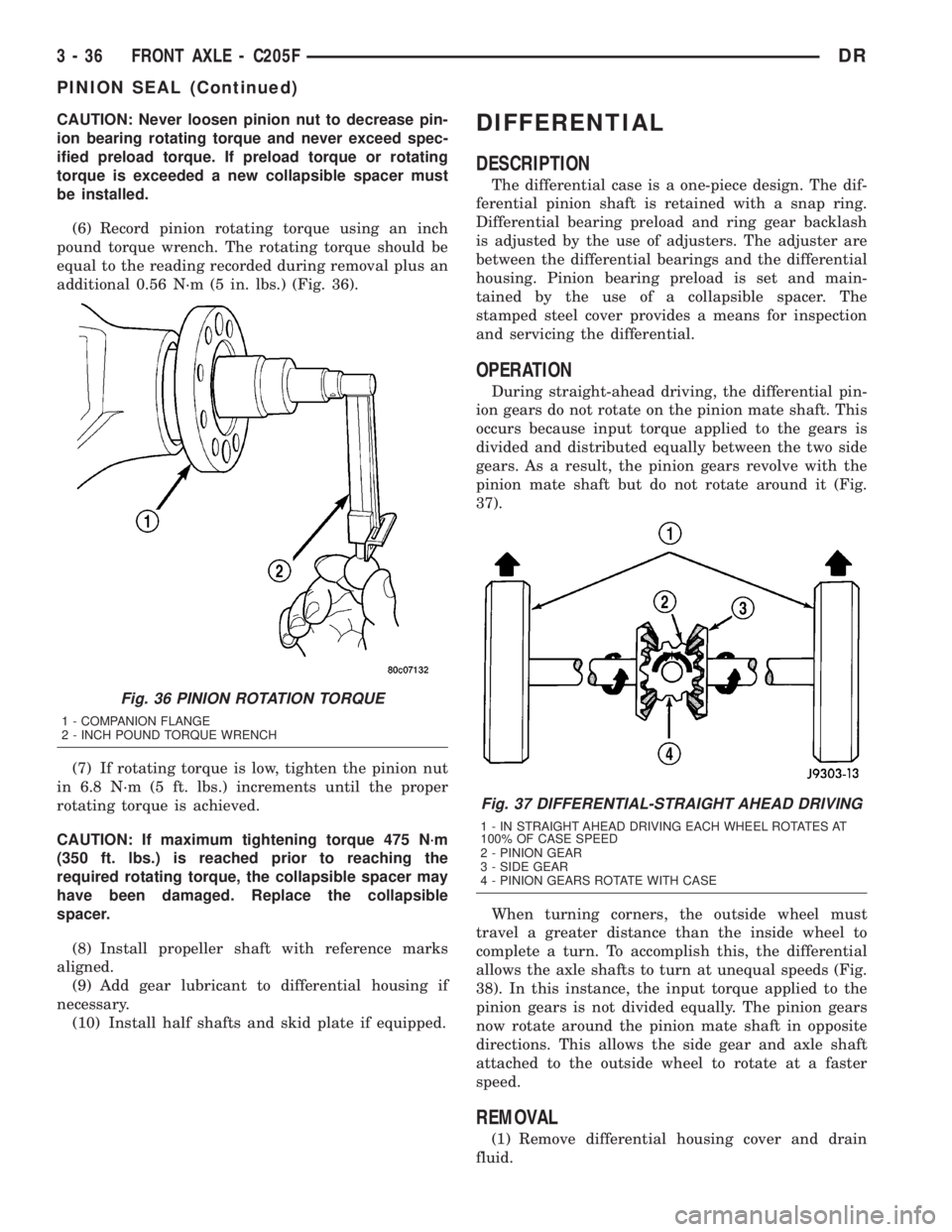
(6) Record pinion rotating torque using an inch
pound torque wrench. The rotating torque should be
equal to the reading recorded during removal plus an
additional 0.56 N´m (5 in. lbs.) (Fig. 36).
(7) If rotating torque is low, tighten the pinion nut
in 6.8 N´m (5 ft. lbs.) increments until the proper
rotating torque is achieved.
CAUTION: If maximum tightening torque 475 N´m
(350 ft. lbs.) is reached prior to reaching the
required rotating torque, the collapsible spacer may
have been damaged. Replace the collapsible
spacer.
(8) Install propeller shaft with reference marks
aligned.
(9) Add gear lubricant to differential housing if
necessary.
(10) Install half shafts and skid plate if equipped.DIFFERENTIAL
DESCRIPTION
The differential case is a one-piece design. The dif-
ferential pinion shaft is retained with a snap ring.
Differential bearing preload and ring gear backlash
is adjusted by the use of adjusters. The adjuster are
between the differential bearings and the differential
housing. Pinion bearing preload is set and main-
tained by the use of a collapsible spacer. The
stamped steel cover provides a means for inspection
and servicing the differential.
OPERATION
During straight-ahead driving, the differential pin-
ion gears do not rotate on the pinion mate shaft. This
occurs because input torque applied to the gears is
divided and distributed equally between the two side
gears. As a result, the pinion gears revolve with the
pinion mate shaft but do not rotate around it (Fig.
37).
When turning corners, the outside wheel must
travel a greater distance than the inside wheel to
complete a turn. To accomplish this, the differential
allows the axle shafts to turn at unequal speeds (Fig.
38). In this instance, the input torque applied to the
pinion gears is not divided equally. The pinion gears
now rotate around the pinion mate shaft in opposite
directions. This allows the side gear and axle shaft
attached to the outside wheel to rotate at a faster
speed.
REMOVAL
(1) Remove differential housing cover and drain
fluid.
Fig. 36 PINION ROTATION TORQUE
1 - COMPANION FLANGE
2 - INCH POUND TORQUE WRENCH
Fig. 37 DIFFERENTIAL-STRAIGHT AHEAD DRIVING
1 - IN STRAIGHT AHEAD DRIVING EACH WHEEL ROTATES AT
100% OF CASE SPEED
2 - PINION GEAR
3 - SIDE GEAR
4 - PINION GEARS ROTATE WITH CASE
3 - 36 FRONT AXLE - C205FDR
PINION SEAL (Continued)
Page 122 of 2895

(6) Position upper and lower suspension arms in
the axle brackets. Install bolts, nuts and align the
suspension alignment cams to the reference marks.
Do not tighten at this time.
(7) Connect track bar to the axle bracket and
install the bolt. Do not tighten at this time.
(8) Install shock absorber and tighten bolts to 121
N´m (89 ft. lbs.).
(9) Install stabilizer bar link to the axle bracket.
Tighten the nut to 68 N´m (50 ft. lbs.).
(10) Install drag link and tie rod to the steering
knuckles and tighten the nuts to 108 N´m (80 ft.
lbs.).
(11) Install ABS wheel speed sensors.
(12) Install rotors and brake calipers.
(13) Connect the axle vent hose.
(14) Install front propeller shaft.
(15) Check and add differential lubricant, if neces-
sary.
(16) Install wheel and tire assemblies.
(17) Remove lower the vehicle.
(18) Tighten upper suspension arm nuts at axle to
149 N´m (110 ft. lbs.). Tighten upper suspension arm
nuts at frame to 149 N´m (110 ft. lbs.).
(19) Tighten lower suspension arm nuts at axle to
190 N´m (140 ft. lbs.). Tighten the lower suspension
arm nuts at frame to 190 N´m (140 ft. lbs.).
(20) Tighten track bar bolt at the axle bracket to
176 N´m (130 ft. lbs.).
(21) Check front wheel alignment.
ADJUSTMENTS
Ring and pinion gears are supplied as matched
sets only. Compensation for pinion depth variance is
achieved with a select shim. The shim is located
between the rear pinion bearing and the pinion gear
head.
PINION DEPTH MEASUREMENT AND ADJUSTMENT
Measurements are taken with pinion bearing cups
and pinion bearings installed in the housing. Take
measurements with Pinion Gauge Set and Dial Indi-
cator C-3339 (Fig. 1).
(1) Assemble Pinion Height Block 6739, Pinion
Block 8878 and rear pinion bearing onto Screw 6741
(Fig. 1).
(2) Insert assembled height gauge components,
rear bearing and screw into the housing through pin-
ion bearing cups (Fig. 2).
(3) Install front pinion bearing and install the
Cone-nut 6740 hand tight. Then check tool rotating
torque with an inch pound torque wrench. The rotat-
ing torque should be 1.7-2.26 N´m (15-20 in. lbs.)
(4) Place Arbor Disc 8289 on Arbor D-115-3 in posi-
tion in the housing side bearing cradles (Fig. 3).(5) Install differential bearing caps on arbor discs
and snug the bearing cap bolts. Then cross tighten
cap bolts to 85 N´m (63 ft. lbs.).
Fig. 1 PINION GEAR DEPTH GAUGE TOOLS
1 - DIAL INDICATOR
2 - ARBOR
3 - PINION HEIGHT BLOCK
4 - CONE
5 - SCREW
6 - PINION BLOCK
7 - SCOOTER BLOCK
8 - ARBOR DISC
Fig. 2 PINION HEIGHT BLOCK
1. PINION HEIGHT BLOCK
2. PINION BLOCK
DRFRONT AXLE - 9 1/4 AA 3 - 49
FRONT AXLE - 9 1/4 AA (Continued)
Page 134 of 2895
ments, until pinion rotating torque is 0.40-0.57 N´m
(3-5 in. lbs.) greater than recorded measurement.
(8) Rotate pinion several times then verify pinion
rotating torque again.
(9) Install axle shafts and hub bearings.
(10) Install propeller shaft with reference marks
aligned.
DIFFERENTIAL
DESCRIPTION
The differential case is a one-piece design. The dif-
ferential pinion shaft is retained with a snap ring.
Differential bearing preload and ring gear backlash
is adjusted by the use of adjusters. The adjuster are
between the differential bearings and the differential
housing. Pinion bearing preload is set and main-
tained by the use of a collapsible spacer. The
stamped steel cover provides a means for inspection
and servicing the differential.
OPERATION
During straight-ahead driving, the differential pin-
ion gears do not rotate on the pinion mate shaft. This
occurs because input torque applied to the gears is
divided and distributed equally between the two side
gears. As a result, the pinion gears revolve with the
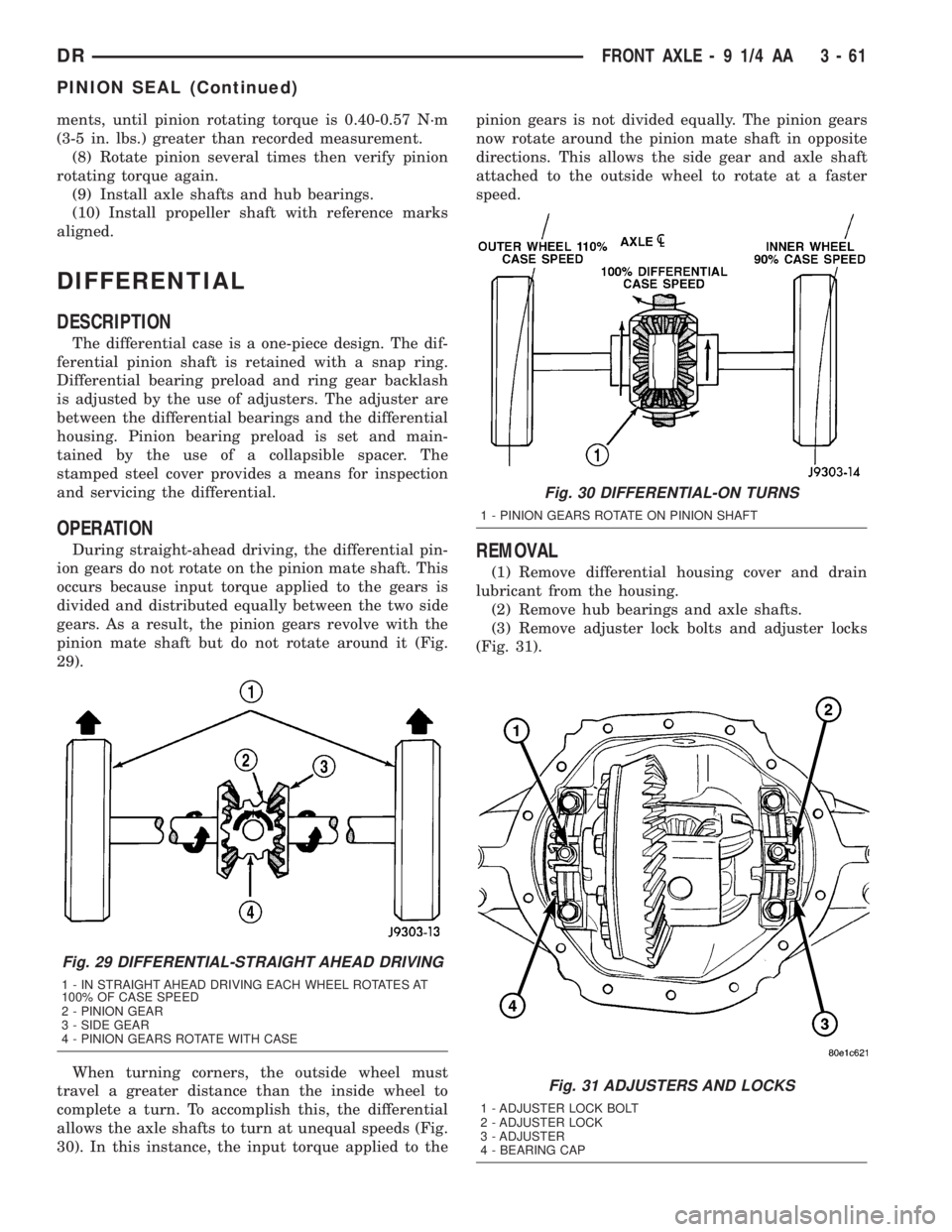
pinion mate shaft but do not rotate around it (Fig.
29).
When turning corners, the outside wheel must
travel a greater distance than the inside wheel to
complete a turn. To accomplish this, the differential
allows the axle shafts to turn at unequal speeds (Fig.
30). In this instance, the input torque applied to thepinion gears is not divided equally. The pinion gears
now rotate around the pinion mate shaft in opposite
directions. This allows the side gear and axle shaft
attached to the outside wheel to rotate at a faster
speed.REMOVAL
(1) Remove differential housing cover and drain
lubricant from the housing.
(2) Remove hub bearings and axle shafts.
(3) Remove adjuster lock bolts and adjuster locks
(Fig. 31).
Fig. 29 DIFFERENTIAL-STRAIGHT AHEAD DRIVING
1 - IN STRAIGHT AHEAD DRIVING EACH WHEEL ROTATES AT
100% OF CASE SPEED
2 - PINION GEAR
3 - SIDE GEAR
4 - PINION GEARS ROTATE WITH CASE
Fig. 30 DIFFERENTIAL-ON TURNS
1 - PINION GEARS ROTATE ON PINION SHAFT
Fig. 31 ADJUSTERS AND LOCKS
1 - ADJUSTER LOCK BOLT
2 - ADJUSTER LOCK
3 - ADJUSTER
4 - BEARING CAP
DRFRONT AXLE - 9 1/4 AA 3 - 61
PINION SEAL (Continued)
Page 159 of 2895
CAUTION: Never loosen pinion nut to decrease pin-
ion bearing rotating torque and never exceed spec-
ified preload torque. If rotating torque is exceeded,
a new collapsible spacer must be installed.(10) If rotating torque is low, use Holder 6719 to
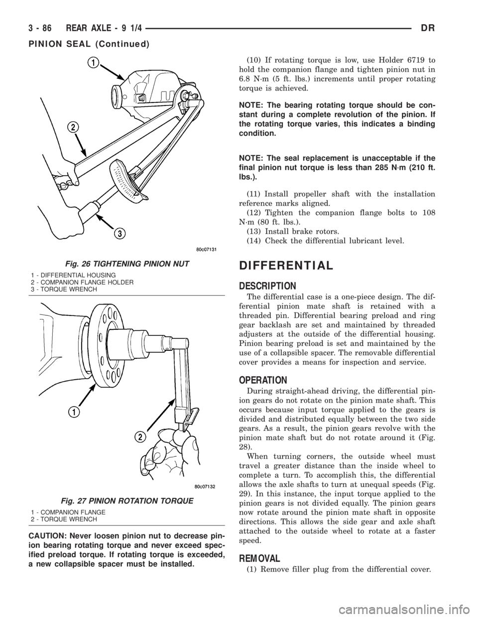
hold the companion flange and tighten pinion nut in
6.8 N´m (5 ft. lbs.) increments until proper rotating
torque is achieved.
NOTE: The bearing rotating torque should be con-
stant during a complete revolution of the pinion. If
the rotating torque varies, this indicates a binding
condition.
NOTE: The seal replacement is unacceptable if the
final pinion nut torque is less than 285 N´m (210 ft.
lbs.).
(11) Install propeller shaft with the installation
reference marks aligned.
(12) Tighten the companion flange bolts to 108
N´m (80 ft. lbs.).
(13) Install brake rotors.
(14) Check the differential lubricant level.
DIFFERENTIAL
DESCRIPTION
The differential case is a one-piece design. The dif-
ferential pinion mate shaft is retained with a
threaded pin. Differential bearing preload and ring
gear backlash are set and maintained by threaded
adjusters at the outside of the differential housing.
Pinion bearing preload is set and maintained by the
use of a collapsible spacer. The removable differential
cover provides a means for inspection and service.
OPERATION
During straight-ahead driving, the differential pin-
ion gears do not rotate on the pinion mate shaft. This
occurs because input torque applied to the gears is
divided and distributed equally between the two side
gears. As a result, the pinion gears revolve with the
pinion mate shaft but do not rotate around it (Fig.
28).
When turning corners, the outside wheel must
travel a greater distance than the inside wheel to
complete a turn. To accomplish this, the differential
allows the axle shafts to turn at unequal speeds (Fig.
29). In this instance, the input torque applied to the
pinion gears is not divided equally. The pinion gears
now rotate around the pinion mate shaft in opposite
directions. This allows the side gear and axle shaft
attached to the outside wheel to rotate at a faster
speed.
REMOVAL
(1) Remove filler plug from the differential cover.
Fig. 26 TIGHTENING PINION NUT
1 - DIFFERENTIAL HOUSING
2 - COMPANION FLANGE HOLDER
3 - TORQUE WRENCH
Fig. 27 PINION ROTATION TORQUE
1 - COMPANION FLANGE
2 - TORQUE WRENCH
3 - 86 REAR AXLE-91/4DR
PINION SEAL (Continued)
Page 161 of 2895
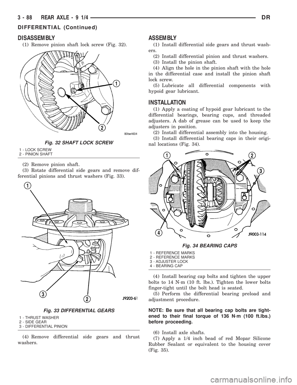
DISASSEMBLY
(1) Remove pinion shaft lock screw (Fig. 32).
(2) Remove pinion shaft.
(3) Rotate differential side gears and remove dif-
ferential pinions and thrust washers (Fig. 33).
(4) Remove differential side gears and thrust
washers.
ASSEMBLY
(1) Install differential side gears and thrust wash-
ers.
(2) Install differential pinion and thrust washers.
(3) Install the pinion shaft.
(4) Align the hole in the pinion shaft with the hole
in the differential case and install the pinion shaft
lock screw.
(5) Lubricate all differential components with
hypoid gear lubricant.
INSTALLATION
(1) Apply a coating of hypoid gear lubricant to the
differential bearings, bearing cups, and threaded
adjusters. A dab of grease can be used to keep the
adjusters in position.
(2) Install differential assembly into the housing.
(3) Install differential bearing caps in their origi-
nal locations (Fig. 34).
(4) Install bearing cap bolts and tighten the upper
bolts to 14 N´m (10 ft. lbs.). Tighten the lower bolts
finger-tight until the bolt head is seated.
(5) Perform the differential bearing preload and
adjustment procedure.
NOTE: Be sure that all bearing cap bolts are tight-
ened to their final torque of 136 N´m (100 ft.lbs.)
before proceeding.
(6) Install axle shafts.
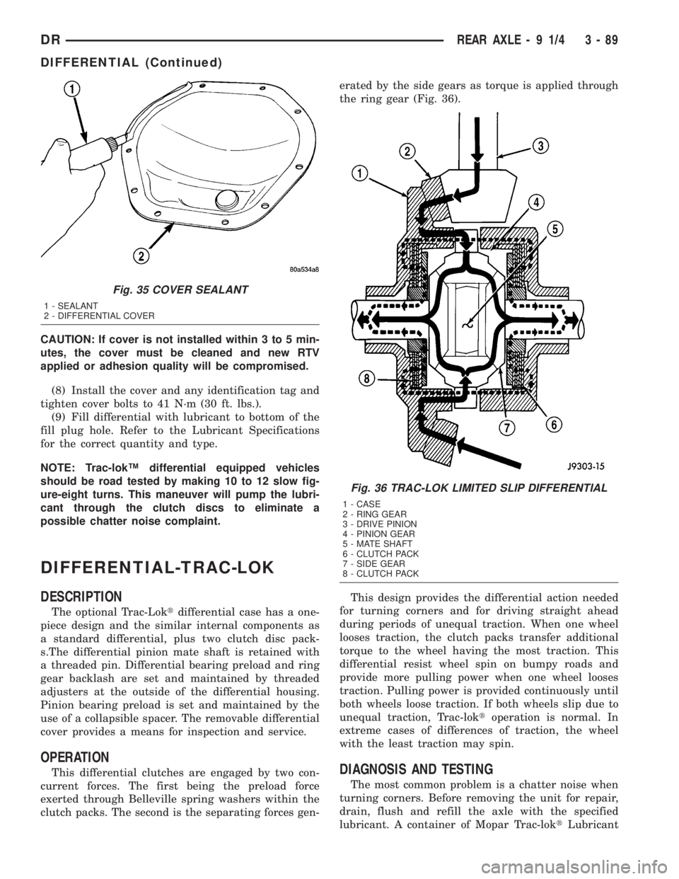
(7) Apply a 1/4 inch bead of red Mopar Silicone
Rubber Sealant or equivalent to the housing cover
(Fig. 35).
Fig. 32 SHAFT LOCK SCREW
1 - LOCK SCREW
2 - PINION SHAFT
Fig. 33 DIFFERENTIAL GEARS
1 - THRUST WASHER
2 - SIDE GEAR
3 - DIFFERENTIAL PINION
Fig. 34 BEARING CAPS
1 - REFERENCE MARKS
2 - REFERENCE MARKS
3 - ADJUSTER LOCK
4 - BEARING CAP
3 - 88 REAR AXLE-91/4DR
DIFFERENTIAL (Continued)
Page 162 of 2895
CAUTION: If cover is not installed within 3 to 5 min-
utes, the cover must be cleaned and new RTV
applied or adhesion quality will be compromised.
(8) Install the cover and any identification tag and
tighten cover bolts to 41 N´m (30 ft. lbs.).
(9) Fill differential with lubricant to bottom of the
fill plug hole. Refer to the Lubricant Specifications
for the correct quantity and type.
NOTE: Trac-lokŸ differential equipped vehicles
should be road tested by making 10 to 12 slow fig-
ure-eight turns. This maneuver will pump the lubri-
cant through the clutch discs to eliminate a
possible chatter noise complaint.
DIFFERENTIAL-TRAC-LOK
DESCRIPTION
The optional Trac-Loktdifferential case has a one-
piece design and the similar internal components as
a standard differential, plus two clutch disc pack-
s.The differential pinion mate shaft is retained with
a threaded pin. Differential bearing preload and ring
gear backlash are set and maintained by threaded
adjusters at the outside of the differential housing.
Pinion bearing preload is set and maintained by the
use of a collapsible spacer. The removable differential
cover provides a means for inspection and service.
OPERATION
This differential clutches are engaged by two con-
current forces. The first being the preload force
exerted through Belleville spring washers within the
clutch packs. The second is the separating forces gen-erated by the side gears as torque is applied through
the ring gear (Fig. 36).
This design provides the differential action needed
for turning corners and for driving straight ahead
during periods of unequal traction. When one wheel
looses traction, the clutch packs transfer additional
torque to the wheel having the most traction. This
differential resist wheel spin on bumpy roads and
provide more pulling power when one wheel looses
traction. Pulling power is provided continuously until
both wheels loose traction. If both wheels slip due to
unequal traction, Trac-loktoperation is normal. In
extreme cases of differences of traction, the wheel
with the least traction may spin.DIAGNOSIS AND TESTING
The most common problem is a chatter noise when
turning corners. Before removing the unit for repair,
drain, flush and refill the axle with the specified
lubricant. A container of Mopar Trac-loktLubricant
Fig. 35 COVER SEALANT
1 - SEALANT
2 - DIFFERENTIAL COVER
Fig. 36 TRAC-LOK LIMITED SLIP DIFFERENTIAL
1 - CASE
2 - RING GEAR
3 - DRIVE PINION
4 - PINION GEAR
5 - MATE SHAFT
6 - CLUTCH PACK
7 - SIDE GEAR
8 - CLUTCH PACK
DRREAR AXLE - 9 1/4 3 - 89
DIFFERENTIAL (Continued)