2003 DODGE RAM oil
[x] Cancel search: oilPage 268 of 2895

DESCRIPTION N´m Ft. Lbs. In. Lbs.
RWAL Valve
Brake Line Fittings19 Ð 170
Rear Wheel Speed Sensor
Mounting Bolt24 Ð 200
FRONT WHEEL SPEED
SENSOR
DESCRIPTION
The ABS brake system uses 3 wheel speed sensors.
A sensor is mounted to each front hub/bearings. The
third sensor is mounted on top of the rear axle dif-
ferential housing.
OPERATION
The Wheel Speed Sensor consists of a magnet sur-
rounded by windings from a single strand of wire.
The sensor sends a small AC signal to the CAB. This
signal is generated by magnetic induction. The mag-
netic induction is created when a toothed sensor ring
(exciter ring or tone wheel) passes the stationary
magnetic WSS.
When the ring gear is rotated, the exciter ring
passes the tip of the WSS. As the exciter ring tooth
approaches the tip of the WSS, the magnetic lines of
force expand, causing the magnetic field to cut across
the sensor's windings. This, in turn causes current to
flow through the WSS circuit (Fig. 1) in one direc-
tion. When the exciter ring tooth moves away from
the sensor tip, the magnetic lines of force collapse
cutting the winding in the opposite direction. This
causes the current to flow in the opposite direction.
Every time a tooth of the exciter ring passes the tip
of the WSS, an AC signal is generated. Each AC sig-
nal (positive to negative signal or sinewave) is inter-
preted by the CAB. It then compares the frequency of
the sinewave to a time value to calculate vehicle
speed. The CAB continues to monitor the frequency
to determine a deceleration rate that would indicate
a possible wheel-locking tendency.
The signal strength of any magnetic induction sen-
sor is directly affected by:
²Magnetic field strength; the stronger the mag-
netic field, the stronger the signal
²Number of windings in the sensor; more wind-
ings provide a stronger signal
²Exciter ring speed; the faster the exciter ring/
tone wheel rotates, the stronger the signal will be
²Distance between the exciter ring teeth and
WSS; the closer the WSS is to the exciter ring/tone
wheel, the stronger the signal will be
The rear WSS is not adjustable. A clearance speci-
fication has been established for manufacturing toler-ances. If the clearance is not within these
specifications, then either the WSS or other compo-
nents may be damaged. The clearance between the
WSS and the exciter ring is 0.005 ± 0.050 in.
The assembly plant performs a ªRolls Testº on
every vehicle that leaves the assembly plant. One of
the test performed is a test of the WSS. To properly
test the sensor, the assembly plant connects test
equipment to the Data Link Connector (DLC). This
connector is located to the right of the steering col-
umn and attached to the lower portion of the instru-
ment panel (Fig. 2). The rolls test terminal is spliced
to the WSS circuit. The vehicle is then driven on a
set of rollers and the WSS output is monitored for
proper operation.
REMOVAL
(1) Remove the front rotor (Refer to 5 - BRAKES/
HYDRAULIC/MECHANICAL/ROTORS - REMOV-
AL).
(2) Remove the wheel speed sensor mounting bolt
from the hub. (Fig. 3)
Fig. 1 Operation of the Wheel Speed Sensor
1 - MAGNETIC CORE
2 - CAB
3 - AIR GAP
4 - EXCITER RING
5 - COIL
DRBRAKES - ABS 5 - 41
BRAKES - ABS (Continued)
Page 275 of 2895

WARNING
WARNING:: EXERCISE CARE WHEN SERVICING
CLUTCH COMPONENTS. FACTORY INSTALLED
CLUTCH DISCS DO NOT CONTAIN ASBESTOS
FIBERS. DUST AND DIRT ON CLUTCH PARTS MAY
CONTAIN ASBESTOS FIBERS FROM AFTERMAR-
KET COMPONENTS. BREATHING EXCESSIVE CON-
CENTRATIONS OF THESE FIBERS CAN CAUSE
SERIOUS BODILY HARM. WEAR A RESPIRATOR
DURING SERVICE AND NEVER CLEAN CLUTCH
COMPONENTS WITH COMPRESSED AIR OR WITH
A DRY BRUSH. EITHER CLEAN THE COMPONENTS
WITH A WATER DAMPENED RAGS OR USE A VAC-
UUM CLEANER SPECIFICALLY DESIGNED FOR
REMOVING ASBESTOS FIBERS AND DUST. DO NOT
CREATE DUST BY SANDING A CLUTCH DISC.
REPLACE THE DISC IF THE FRICTION MATERIAL IS
DAMAGED OR CONTAMINATED. DISPOSE OF ALL
DUST AND DIRT CONTAINING ASBESTOS FIBERS
IN SEALED BAGS OR CONTAINERS. THIS WILL
HELP MINIMIZE EXPOSURE TO YOURSELF AND TO
OTHERS. FOLLOW ALL RECOMMENDED SAFETY
PRACTICES PRESCRIBED BY THE OCCUPATIONAL
SAFETY AND HEALTH ADMINISTRATION (OSHA)
AND THE ENVIRONMENTAL SAFETY AGENCY(EPA), FOR THE HANDLING AND DISPOSAL OF
PRODUCTS CONTAINING ASBESTOS.
DIAGNOSIS AND TESTING
A road test and component inspection is recom-
mended to determine a clutch problem. During a
road test, drive the vehicle at normal speeds. Shift
the transmission through all gear ranges and observe
clutch action. If the clutch chatters, grabs, slips or
does not release properly, remove and inspect the
clutch components. If the problem is noise or hard
shifting, further diagnosis may be needed as the
transmission or another driveline component may be
at fault.
CLUTCH CONTAMINATION
Fluid contamination is a frequent cause of clutch
malfunctions. Oil, water or clutch fluid on the clutch
disc and pressure plate surfaces will cause chatter,
slip and grab. Inspect components for oil, hydraulic
fluid or water/road splash contamination.
Oil contamination indicates a leak at either the
rear main seal or transmission input shaft. Clutch
fluid leaks are usually from damaged slave cylinder
push rod seals. Heat buildup caused by slippage
between the pressure plate, disc and flywheel can
bake the oil residue onto the components. The glaze-
like residue ranges in color from amber to black.
Road splash contamination is dirt/water entering
the clutch housing due to loose bolts, housing cracks.
Driving through deep water puddles can force water/
road splash into the housing through such openings.
IMPROPER RELEASE OR CLUTCH ENGAGEMENT
Clutch release or engagement problems can be
caused by worn or damage clutch components. A
visual inspection of the release components will usu-
ally reveal the problem part.
Release problems can result in hard shifting and
noise. Look for leaks at the clutch cylinders and
interconnecting line and loose slave cylinder bolts.
Also worn/loose release fork, pivot stud, clutch disc,
pressure plate or release bearing.
Engagement problems can result in slip, chatter/
shudder and noisy operation. The causes may be
clutch disc contamination, wear, distortion or fly-
wheel damage. Visually inspect to determine the
actual cause of the problem.
CLUTCH MISALIGNMENT
Clutch components must be in proper alignment
with the crankshaft and transmission input shaft.
Misalignment caused by excessive runout or warpage
of any clutch component will cause grab, chatter and
improper clutch release.
Fig. 2 CLUTCH OPERATION
1 - FLYWHEEL
2 - PRESSURE PLATE FINGERS
3 - PIVOT POINT
4 - RELEASE BEARING PUSHED IN
5 - CLUTCH DISC ENGAGED
6 - CLUTCH DISC ENGAGED
7 - RELEASE BEARING
6 - 2 CLUTCHDR
CLUTCH (Continued)
Page 276 of 2895
CLUTCH COVER AND DISC RUNOUT
Check the clutch disc before installation. Axial
(face) runout of anewdisc should not exceed 0.50
mm (0.020 in.). Measure runout about 6 mm (1/4 in.)
from the outer edge of the disc facing. Obtain
another disc if runout is excessive.
Check condition of the clutch before installation. A
warped cover or diaphragm spring will cause grab
and incomplete release or engagement. Be careful
when handling the cover and disc. Impact can distort
the cover, diaphragm spring, release fingers and the
hub of the clutch disc.
Use an alignment tool when positioning the disc on
the flywheel. The tool prevents accidental misalign-
ment which could result in cover distortion and disc
damage.
A frequent cause of clutch cover distortion (and
consequent misalignment) is improper bolt tighten-
ing.
FLYWHEEL RUNOUT
Check flywheel runout whenever misalignment is
suspected. Flywheel runout should not exceed 0.08
mm (0.003 in.). Measure runout at the outer edge of
the flywheel face with a dial indicator.
Common causes of runout are:
²heat warpage
²improper machining
²incorrect bolt tightening
²improper seating on crankshaft flange shoulder²foreign material on crankshaft flange
Flywheel machining is not recommended. The fly-
wheel clutch surface is machined to a unique contour
and machining will negate this feature. Minor fly-
wheel scoring can be cleaned up by hand with 180
grit emery or with turning equipment. Remove only
enough material to reduce scoring (approximately
0.001 - 0.003 in.). Heavy stock removal isnot rec-
ommended.Replace the flywheel if scoring is severe
and deeper than 0.076 mm (0.003 in.). Excessive
stock removal can result in flywheel cracking or
warpage after installation; it can also weaken the fly-
wheel and interfere with proper clutch release.
Clean the crankshaft flange before mounting the
flywheel. Dirt and grease on the flange surface may
cock the flywheel causing excessive runout. Use new
bolts when remounting a flywheel and secure the
bolts with Mopar Lock And Seal or equivalent.
Tighten flywheel bolts to specified torque only. Over-
tightening can distort the flywheel hub causing
runout.DIAGNOSIS CHART
The diagnosis charts Diagnosis Chart describe
common clutch problems, causes and correction.
Fault conditions are listed at the top of each chart.
Conditions, causes and corrective action are outlined
in the indicated columns.
The charts are provided as a convenient reference
when diagnosing faulty clutch operation.
DIAGNOSIS CHART
CONDITION POSSIBLE CAUSES CORRECTION
Disc facing worn out 1. Normal wear. 1. Replace cover and disc.
2. Driver frequently rides (slips) the
clutch. Results in rapid overheating
and wear.2. Replace cover and disc.
3. Insufficient clutch cover
diaphragm spring tension.3. Replace cover and disc.
Clutch disc facing contaminated with
oil, grease, or clutch fluid.1. Leak at rear main engine seal or
transmission input shaft seal.1. Replace appropriate seal.
2. Excessive amount of grease
applied to the input shaft splines.2. Remove grease and apply the
correct amount of grease.
3. Road splash, water entering
housing.3. Replace clutch disc. Clean clutch
cover and reuse if in good condition.
4. Slave cylinder leaking. 4. Replace hydraulic clutch linkage.
Clutch is running partially
disengaged.1. Release bearing sticking or
binding and does not return to the
normal running position.1. Verify failure. Replace the release
bearing and transmission front
bearing retainer as necessary.
DRCLUTCH 6 - 3
CLUTCH (Continued)
Page 289 of 2895

DESCRIPTIONÐCOOLING SYSTEM FLOW -
5.9L DIESEL
The diesel engine cooling system consists of :
²Cross-flow radiator
²Belt driven water pump
²Belt driven mechanical cooling fan
²Electronic viscous fan drive
²Fan shroud
²Radiator pressure cap²Vertically mounted thermostat
²Coolant reserve/recovery system
²Transmission oil cooler
²Coolant
Coolant flow circuits for the 5.9L diesel engine are
shown in (Fig. 3).
Fig. 1 Engine Cooling System Flow - 3.7L/4.7L
1 - LH CYL. HEAD
2 - BLEED
3 - THERMOSTAT LOCATION
4 - RH CYL. HEAD
5 - RH BANK CYL. BLOCK6 - LH BANK CYL. BLOCK
7 - COOLANT TEMP. SENSOR
8 - FROM HEATER CORE
9 - TO HEATER CORE
7 - 2 COOLINGDR
COOLING (Continued)
Page 293 of 2895
lower inside sealing seat for nicks, cracks, paint, dirt
and solder residue. Inspect the radiator-to- reserve/
overflow tank hose for internal obstructions. Insert a
wire through the hose to be sure it is not obstructed.
Inspect the cams on the outside of the filler neck.
If the cams are damaged, seating of the pressure cap
valve and tester seal will be affected.
Attach pressure tester (7700 or an equivalent) to
radiator filler neck.
Operate the tester pump to apply 103.4 kPa (15
psi) pressure to the system. If the hoses enlarge
excessively or bulges while testing, replace as neces-
sary. Observe the gauge pointer and determine the
condition of the cooling system according to following
criteria:
Holds Steady:If the pointer remains steady for
two minutes, serious coolant leaks are not present in
system. However, there could be an internal leak
that does not appear with normal system test pres-
sure. If it is certain that coolant is being lost and
leaks cannot be detected, inspect for interior leakage
or perform Internal Leakage Test. Refer to INTER-
NAL LEAKAGE INSPECTION.
Drops Slowly:Indicates a small leak or seepage
is occurring. Examine all of the connections for seep-
age or slight leakage with a flashlight. Inspect the
radiator, hoses, gasket edges and heater. Seal the
small leak holes with a Sealer Lubricant (or equiva-
lent). Repair the leak holes and inspect the system
again with pressure applied.Drops Quickly:Indicates that serious leakage is
occurring. Examine the system for external leakage.
If leaks are not visible, inspect for internal leakage.
Large radiator leak holes should be repaired by a
reputable radiator repair shop.
INTERNAL LEAKAGE INSPECTION
Remove the engine oil pan drain plug and drain a
small amount of engine oil. If coolant is present in
the pan, it will drain first because it is heavier than
oil. An alternative method is to operate engine for a
short period to churn the oil. After this is done,
remove the engine dipstick and inspect for water
globules. Also inspect the transmission dipstick for
water globules and transmission fluid cooler for leak-
age.
WARNING: WITH RADIATOR PRESSURE TESTER
TOOL INSTALLED ON RADIATOR, DO NOT ALLOW
PRESSURE TO EXCEED 145 kPa (21 PSI). PRES-
SURE WILL BUILD UP QUICKLY IF A COMBUSTION
LEAK IS PRESENT. TO RELEASE PRESSURE,
ROCK TESTER FROM SIDE TO SIDE. WHEN
REMOVING TESTER, DO NOT TURN TESTER MORE
THAN 1/2 TURN IF SYSTEM IS UNDER PRESSURE.
Operate the engine without the pressure cap on
the radiator until the thermostat opens. Attach a
Pressure Tester to the filler neck. If pressure builds
up quickly it indicates a combustion leak exists. This
is usually the result of a cylinder head gasket leak or
crack in engine. Repair as necessary.
If there is not an immediate pressure increase,
pump the Pressure Tester. Do this until indicated
pressure is within system range of 110 kPa (16 psi).
Fluctuation of the gauge pointer indicates compres-
sion or combustion leakage into cooling system.
Because the vehicle is equipped with a catalytic
converter,do notshort out cylinders to isolate com-
pression leak.
If the needle on dial of the pressure tester does not
fluctuate, race engine a few times to check for an
abnormal amount of coolant or steam. This would be
emitting from exhaust pipe. Coolant or steam from
exhaust pipe may indicate a faulty cylinder head gas-
ket, cracked engine cylinder block or cylinder head.
A convenient check for exhaust gas leakage into
cooling system is provided by a commercially avail-
able Block Leak Check tool. Follow manufacturers
instructions when using this product.
COMBUSTION LEAKAGE TESTÐWITHOUT
PRESSURE TESTER
DO NOT WASTE reusable coolant. If the solution
is clean, drain the coolant into a clean container for
reuse.
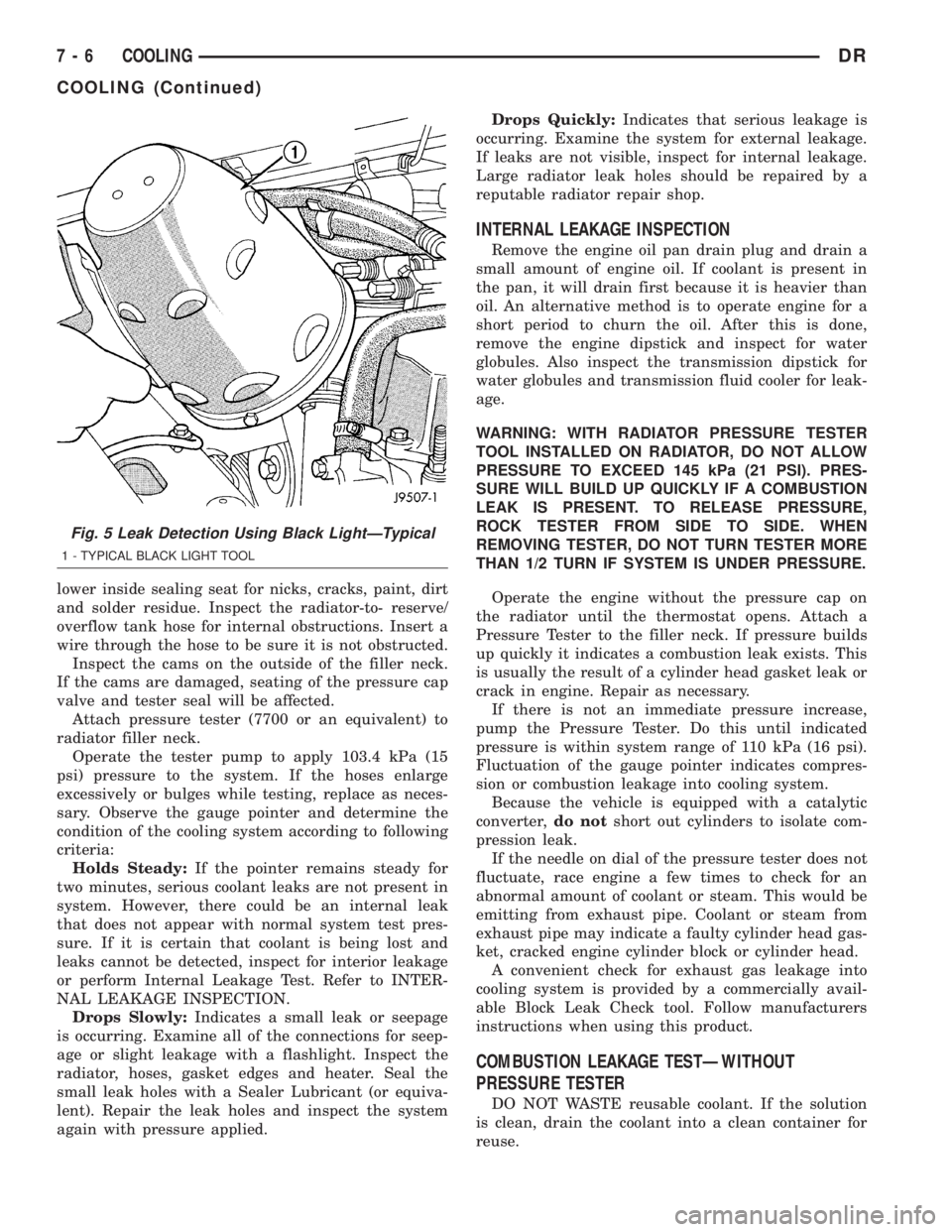
Fig. 5 Leak Detection Using Black LightÐTypical
1 - TYPICAL BLACK LIGHT TOOL
7 - 6 COOLINGDR
COOLING (Continued)
Page 294 of 2895

WARNING: DO NOT REMOVE CYLINDER BLOCK
DRAIN PLUGS OR LOOSEN RADIATOR DRAIN-
COCK WITH SYSTEM HOT AND UNDER PRESSURE.
SERIOUS BURNS FROM COOLANT CAN OCCUR.
Drain sufficient coolant to allow thermostat
removal. (Refer to 7 - COOLING/ENGINE/ENGINE
COOLANT THERMOSTAT - REMOVAL). Remove
accessory drive belt (Refer to 7 - COOLING/ACCES-
SORY DRIVE/DRIVE BELTS - REMOVAL).
Add coolant to radiator to bring level to within 6.3
mm (1/4 in) of the top of the thermostat housing.CAUTION: Avoid overheating. Do not operate
engine for an excessive period of time. Open drain-
cock immediately after test to eliminate boil over.
Start engine and accelerate rapidly three times, to
approximately 3000 rpm while observing coolant. If
internal engine combustion gases are leaking into
cooling system, bubbles will appear in coolant. If bub-
bles do not appear, internal combustion gas leakage
is not present.
DIAGNOSIS AND TESTING - COOLING SYSTEM
DIESEL ENGINE
COOLING SYSTEM DIAGNOSISÐDIESEL ENGINE
CONDITION POSSIBLE CAUSES CORRECTION
TEMPERATURE GAUGE READS
LOWNOTE:
Information on dash cluster is
displayed based on broadcast data
from ECM. DTC will be set for
engine sensor circuit concern.1. Vehicle is equipped with a heavy
duty cooling system.1. None. System operating normally.
2. Thermostat stuck open 2. Inspect and test thermostat.
3. Coolant level low. 3. Fill cooling system. (Refer to 7 -
COOLING - STANDARD
PROCEDURE)
4. Temperature gauge not
functioning correctly.4. Check cluster (Refer to 8 -
ELECTRICAL/INSTRUMENT
CLUSTER - DIAGNOSIS AND
TESTING)
DRCOOLING 7 - 7
COOLING (Continued)
Page 299 of 2895

CONDITION POSSIBLE CAUSES CORRECTION
TEMPERATURE GAUGE
READS HIGH OR THE
COOLANT WARNING LAMP
ILLUMINATES. COOLANT MAY
OR MAY NOT BE LOST OR
LEAKING FROM THE COOLING
SYSTEM1. Trailer is being towed, a steep
hill is being climbed, vehicle is
operated in slow moving traffic,
or engine is being idled with
very high ambient (outside)
temperatures and the air
conditioning is on. Higher
altitudes could aggravate these
conditions.1. This may be a temporary condition and
repair is not necessary. Turn off the air
conditioning and attempt to drive the
vehicle without any of the previous
conditions. Observe the temperature
gauge. The gauge should return to the
normal range. If the gauge does not return
to the normal range, determine the cause
for overheating and repair. Refer to
Possible Causes (2-18).
2. Is the temperature gauge
reading correctly?2. Check gauge. (Refer to 8 -
ELECTRICAL/INSTRUMENT CLUSTER -
SCHEMATIC - ELECTRICAL). Repair as
necessary.
3. Is the temperature warning
illuminating unnecessarily?3. (Refer to 8 - ELECTRICAL/
INSTRUMENT CLUSTER - SCHEMATIC -
ELECTRICAL).
4. Coolant low in coolant
reserve/overflow tank and
radiator?4. Check for coolant leaks and repair as
necessary. (Refer to 7 - COOLING -
DIAGNOSIS AND TESTING).
5. Pressure cap not installed
tightly. If cap is loose, boiling
point of coolant will be lowered.
Also refer to the following Step
6.5. Tighten cap
6. Poor seals at the radiator
cap.6. (a) Check condition of cap and cap
seals. Refer to Radiator Cap. Replace cap
if necessary.
(b) Check condition of radiator filler neck.
If neck is bent or damaged, replace
radiator (5.9L) or degas bottle (3.7L, 4.7L).
7. Coolant level low in radiator
but not in coolant reserve/
overflow tank. This means the
radiator is not drawing coolant
from the coolant reserve/
overflow tank as the engine
cools (5.9L).7. (a) Check condition of radiator cap and
cap seals. Refer to Radiator Cap in this
Group. Replace cap if necessary.
(b) Check condition of radiator filler neck.
If neck is bent or damaged, replace
radiator.
(c) Check condition of the hose from the
radiator to the coolant tank. It should fit
tight at both ends without any kinks or
tears. Replace hose if necessary.
(d) Check coolant reserve/overflow tank
and tanks hoses for blockage. Repair as
necessary.
8. Incorrect coolant
concentration8. Check coolant. (Refer to LUBRICATION
& MAINTENANCE/FLUID TYPES -
DESCRIPTION).
9. Coolant not flowing through
system9. Check for coolant flow at radiator filler
neck with some coolant removed, engine
warm and thermostat open. Coolant
should be observed flowing through
radiator. If flow is not observed, determine
area of obstruction and repair as
necessary.
7 - 12 COOLINGDR
COOLING (Continued)
Page 301 of 2895

CONDITION POSSIBLE CAUSES CORRECTION
Temperature gauge reading is
inconsistent (flucttuates, cycles
or is erratic)1. During cold weather
operation, with the heater blower
in the high position, the gauge
reading may drop slightly.1. A normal condition. No correction
necessary.
2. Temperature gauge or engine
mounted gauge sensor defective
or shorted. Also, corroded or
loose wiring in this circuit.2. Check operation of gauge and repair if
necessary. (Refer to 8 - ELECTRICAL/
INSTRUMENT CLUSTER - DIAGNOSIS
AND TESTING).
3. Gauge reading rises when
vehicle is brought to a stop after
heavy use (engine still running)3. A normal condition. No correction is
necessary. Gauge should return to normal
range after vehicle is driven.
4. Gauge reading high after
re-starting a warmed up (hot)
engine.4. A normal condition. No correction is
necessary. The gauge should return to
normal range after a few minutes of
engine operation.
5. Coolant level low in radiator
(air will build up in the cooling
system causing the thermostat
to open late).5. Check and correct coolant leaks. (Refer
to 7 - COOLING - DIAGNOSIS AND
TESTING).
6. Cylinder head gasket leaking
allowing exhaust gas to enter
cooling system causing a
thermostat to open late.6. (a) Check for cylinder head gasket
leaks. (Refer to 7 - COOLING -
DIAGNOSIS AND TESTING).
(b) Check for coolant in the engine oil.
Inspect for white steam emitting from the
exhaust system. Repair as necessary.
7. Water pump impeller loose on
shaft.7. Check water pump and replace as
necessary. (Refer to 7 - COOLING/
ENGINE/WATER PUMP - REMOVAL).
8. Loose accessory drive belt.
(water pump slipping)8. (Refer to 7 - COOLING/ACCESSORY
DRIVE/DRIVE BELTS - DIAGNOSIS AND
TESTING). Check and correct as
necessary.
9. Air leak on the suction side of
the water pump allows air to
build up in cooling system
causing thermostat to open late.9. Locate leak and repair as necessary.
PRESSURE CAP IS BLOWING
OFF STEAM AND/OR
COOLANT TO COOLANT TANK.
TEMPERATURE GAUGE
READING MAY BE ABOVE
NORMAL BUT NOT HIGH.
COOLANT LEVEL MAY BE
HIGH IN COOLANT RESERVE/
OVERFLOW TANK1. Pressure relief valve in
radiator cap is defective.1. Check condition of radiator cap and cap
seals. (Refer to 7 - COOLING/ENGINE/
RADIATOR PRESSURE CAP -
DIAGNOSIS AND TESTING). Replace cap
as necessary.
COOLANT LOSS TO THE
GROUND WITHOUT
PRESSURE CAP BLOWOFF.
GAUGE READING HIGH OR
HOT1. Coolant leaks in radiator,
cooling system hoses, water
pump or engine.1. Pressure test and repair as necessary.
(Refer to 7 - COOLING - DIAGNOSIS
AND TESTING).
7 - 14 COOLINGDR
COOLING (Continued)