2003 DODGE RAM oil
[x] Cancel search: oilPage 66 of 2895
STABILIZER BAR
REMOVAL
(1) Raise and support the vehicle.
(2) Hold the stabilizer link shafts with a wrench
and remove the link nuts at the stabilizer bar.
(3) Remove the retainers and grommets from the
stabilizer bar links.
(4) Remove the stabilizer bar link nuts from the
axle brackets.
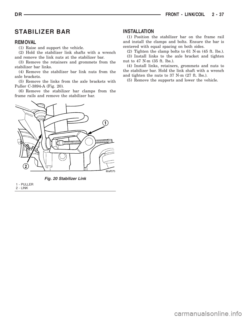
(5) Remove the links from the axle brackets with
Puller C-3894-A (Fig. 20).
(6) Remove the stabilizer bar clamps from the
frame rails and remove the stabilizer bar.
INSTALLATION
(1) Position the stabilizer bar on the frame rail
and install the clamps and bolts. Ensure the bar is
centered with equal spacing on both sides.
(2) Tighten the clamp bolts to 61 N´m (45 ft. lbs.).
(3) Install links to the axle bracket and tighten
nut to 47 N´m (35 ft. lbs.).
(4) Install links, retainers, grommets and nuts to
the stabilizer bar. Hold the link shaft with a wrench
and tighten the nuts to 37 N´m (27 ft. lbs.).
(5) Remove the supports and lower the vehicle.
Fig. 20 Stabilizer Link
1 - PULLER
2 - LINK
DRFRONT - LINK/COIL 2 - 37
Page 67 of 2895
REAR
TABLE OF CONTENTS
page page
REAR
DESCRIPTION.........................38
DIAGNOSIS AND TESTING - SPRING AND
SHOCK.............................38
SPECIFICATIONS
TORQUE CHART......................39
BUSHINGS
REMOVAL.............................39
INSTALLATION.........................39
JOUNCE BUMPER
REMOVAL.............................40
INSTALLATION.........................40
AUXILIARY SPRING BUMPERS (3500)
REMOVAL.............................40INSTALLATION.........................40
SHOCK
REMOVAL.............................40
INSTALLATION.........................40
SPRING
DESCRIPTION.........................41
OPERATION...........................41
REMOVAL.............................41
INSTALLATION.........................41
SPRING TIP INSERTS
REMOVAL.............................41
INSTALLATION.........................42
REAR
DESCRIPTION
The rear suspension is comprised of:
²Shock Absorbers
²Jounce Bumpers
²Stabilizer Bar (optional)
²Leaf Springs
²Auxiliary Leaf Spring (3500 series)
²Auxiliary Spring Bumpers (3500 series)
²Drive Axle
CAUTION: A vehicle should always be loaded so
the vehicle weight center-line is located immedi-
ately forward of the rear axle. Correct vehicle load-
ing provides proper front tire-to-road contact. This
results in maximum vehicle handling stability and
safety. Incorrect vehicle weight distribution can
cause excessive tire tread wear, spring fatigue or
failure, and erratic steering.
CAUTION: Suspension components with rubber/ure-
thane bushings (except stabilizer bar) should be
tightened with the vehicle at normal ride height. It is
important to have the springs supporting the weight
of the vehicle when the fasteners are torqued. If
springs are not at their normal ride position, vehicle
ride comfort could be affected and premature bush-
ing wear may occur.
DIAGNOSIS AND TESTING - SPRING AND
SHOCK
A knocking or rattling noise from a shock absorber
may be caused by movement between mounting
bushings and metal brackets or attaching compo-
nents. These noises can usually be stopped by tight-
ening the attaching nuts. If the noise persists,
inspect for damaged and worn bushings, and attach-
ing components. Repair as necessary if any of these
conditions exist.
A squeaking noise from the shock absorber may be
caused by the hydraulic valving and may be intermit-
tent. This condition is not repairable and the shock
absorber must be replaced.
The shock absorbers are not refillable or adjust-
able. If a malfunction occurs, the shock absorber
must be replaced. To test a shock absorber, hold it in
an upright position and force the piston in and out of
the cylinder four or five times. The action throughout
each stroke should be smooth and even.
The spring eye and shock absorber bushings do not
require any type of lubrication. Do not attempt to
stop spring bushing noise by lubricating them.
Grease and mineral oil-base lubricants will deterio-
rate the bushing rubber.
If the vehicle is used for severe, off-road operation,
the springs should be examined periodically. Check
for broken and shifted leafs, loose and missing clips,
and broken center bolts. Refer to Spring and Shock
Absorber Diagnosis chart for additional information.
2 - 38 REARDR
Page 71 of 2895
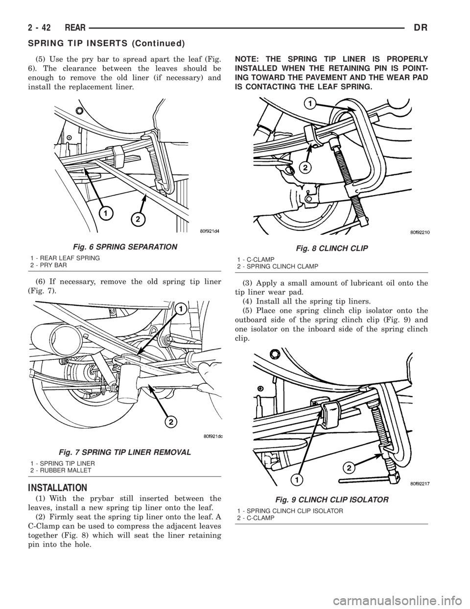
(5) Use the pry bar to spread apart the leaf (Fig.
6). The clearance between the leaves should be
enough to remove the old liner (if necessary) and
install the replacement liner.
(6) If necessary, remove the old spring tip liner
(Fig. 7).
INSTALLATION
(1) With the prybar still inserted between the
leaves, install a new spring tip liner onto the leaf.
(2) Firmly seat the spring tip liner onto the leaf. A
C-Clamp can be used to compress the adjacent leaves
together (Fig. 8) which will seat the liner retaining
pin into the hole.NOTE: THE SPRING TIP LINER IS PROPERLY
INSTALLED WHEN THE RETAINING PIN IS POINT-
ING TOWARD THE PAVEMENT AND THE WEAR PAD
IS CONTACTING THE LEAF SPRING.
(3) Apply a small amount of lubricant oil onto the
tip liner wear pad.
(4) Install all the spring tip liners.
(5) Place one spring clinch clip isolator onto the
outboard side of the spring clinch clip (Fig. 9) and
one isolator on the inboard side of the spring clinch
clip.
Fig. 6 SPRING SEPARATION
1 - REAR LEAF SPRING
2-PRYBAR
Fig. 7 SPRING TIP LINER REMOVAL
1 - SPRING TIP LINER
2 - RUBBER MALLET
Fig. 8 CLINCH CLIP
1 - C-CLAMP
2 - SPRING CLINCH CLAMP
Fig. 9 CLINCH CLIP ISOLATOR
1 - SPRING CLINCH CLIP ISOLATOR
2 - C-CLAMP
2 - 42 REARDR
SPRING TIP INSERTS (Continued)
Page 113 of 2895
PINION GEAR/RING GEAR
REMOVAL
NOTE: The ring gear and pinion are serviced in a
matched set. Never replace one without replacing
the other.
(1) Remove differential from housing.
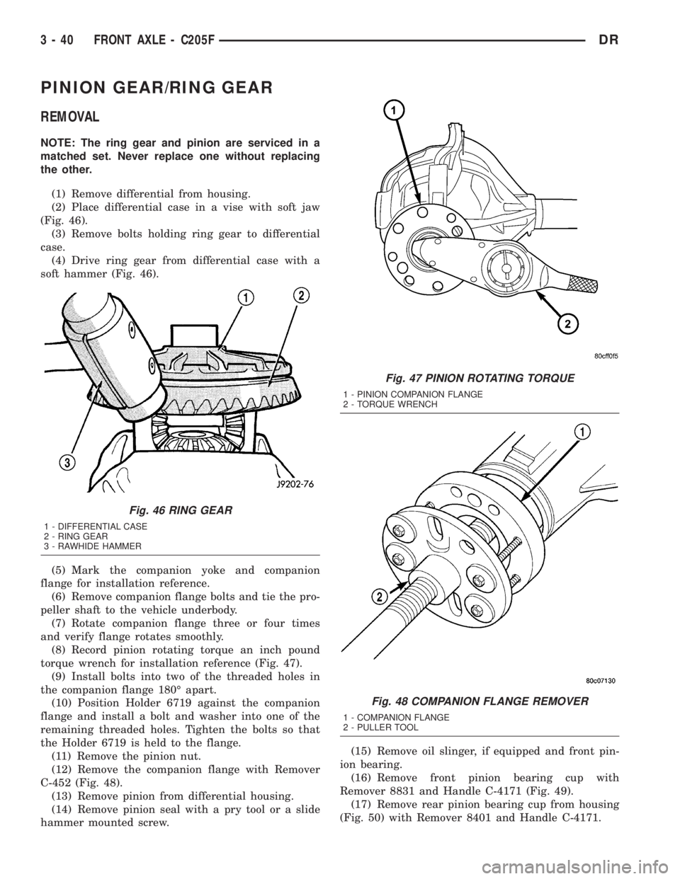
(2) Place differential case in a vise with soft jaw
(Fig. 46).
(3) Remove bolts holding ring gear to differential
case.
(4) Drive ring gear from differential case with a
soft hammer (Fig. 46).
(5) Mark the companion yoke and companion
flange for installation reference.
(6) Remove companion flange bolts and tie the pro-
peller shaft to the vehicle underbody.
(7) Rotate companion flange three or four times
and verify flange rotates smoothly.
(8) Record pinion rotating torque an inch pound
torque wrench for installation reference (Fig. 47).
(9) Install bolts into two of the threaded holes in
the companion flange 180É apart.
(10) Position Holder 6719 against the companion
flange and install a bolt and washer into one of the
remaining threaded holes. Tighten the bolts so that
the Holder 6719 is held to the flange.
(11) Remove the pinion nut.
(12) Remove the companion flange with Remover
C-452 (Fig. 48).
(13) Remove pinion from differential housing.
(14) Remove pinion seal with a pry tool or a slide
hammer mounted screw.(15) Remove oil slinger, if equipped and front pin-
ion bearing.
(16) Remove front pinion bearing cup with
Remover 8831 and Handle C-4171 (Fig. 49).
(17) Remove rear pinion bearing cup from housing
(Fig. 50) with Remover 8401 and Handle C-4171.
Fig. 46 RING GEAR
1 - DIFFERENTIAL CASE
2 - RING GEAR
3 - RAWHIDE HAMMER
Fig. 47 PINION ROTATING TORQUE
1 - PINION COMPANION FLANGE
2 - TORQUE WRENCH
Fig. 48 COMPANION FLANGE REMOVER
1 - COMPANION FLANGE
2 - PULLER TOOL
3 - 40 FRONT AXLE - C205FDR
Page 121 of 2895

Condition Possible Causes Correction
Gear Teeth Broke 1. Overloading. 1. Replace gears. Examine other
gears and bearings for possible
damage.
2. Erratic clutch operation. 2. Replace gears and examine the
remaining parts for damage. Avoid
erratic clutch operation.
3. Ice-spotted pavement. 3. Replace gears and examine
remaining parts for damage.
4. Improper adjustments. 4. Replace gears and examine
remaining parts for damage. Ensure
ring gear backlash is correct.
Axle Noise 1. Insufficient lubricant. 1. Fill differential with the correct
fluid type and quantity.
2. Improper ring gear and pinion
adjustment.2. Check ring gear and pinion
contact pattern.
3. Unmatched ring gear and pinion. 3. Replace gears with a matched
ring gear and pinion.
4. Worn teeth on ring gear and/or
pinion.4. Replace ring gear and pinion.
5. Loose pinion bearings. 5. Adjust pinion bearing pre-load.
6. Loose differential bearings. 6. Adjust differential bearing
pre-load.
7. Mis-aligned or sprung ring gear. 7. Measure ring gear run-out.
Replace components as necessary.
8. Loose differential bearing cap
bolts.8. Inspect differential components
and replace as necessary. Ensure
that the bearing caps are torqued
tot he proper specification.
9. Housing not machined properly. 9. Replace housing.
REMOVAL
(1) Remove wheels and tires.
(2) Remove brake calipers and rotors.
(3) Disconnect ABS wheel speed sensors.
(4) Disconnect axle vent hose.
(5) Remove front propeller shaft.
(6) Disconnect stabilizer bar links at the axle
brackets.
(7) Disconnect shock absorbers from axle brackets.
(8) Disconnect track bar from the axle bracket.
(9) Disconnect tie rod and drag link from the steer-
ing knuckles.
(10) Position suitable lifting device under the axle
assembly.
(11) Secure axle to lifting device.
(12) Mark suspension alignment cams for installa-
tion reference.
(13) Disconnect upper and lower suspension arms
from the axle bracket.(14) Lower the axle. The coil springs will drop
with the axle.
(15) Remove the coil springs from the axle bracket.
INSTALLATION
CAUTION: Suspension components with rubber
bushings should be tightened with the weight of the
vehicle on the suspension, at normal height. If
springs are not at their normal ride position, vehicle
ride comfort could be affected and premature bush-
ing wear may occur. Rubber bushings must never
be lubricated.
(1) Support the axle on a suitable lifting device.
(2) Secure axle to lifting device.
(3) Position the axle under the vehicle.
(4) Install springs, retainer clip and bolts.
(5) Raise axle and align it with the spring pads.
3 - 48 FRONT AXLE - 9 1/4 AADR
FRONT AXLE - 9 1/4 AA (Continued)
Page 129 of 2895

AXLE SHAFTS
REMOVAL
(1) Remove wheel and tire assembly.
(2) Remove brake caliper, rotor and ABS wheel
speed sensor if equipped.
(3) Remove axle shaft cotter pin, hub nut and
washer (Fig. 14).
(4) Remove the four hub bearing bolts (Fig. 15)
from the back of the steering knuckle.
(5) Remove hub bearing from the steering knuckle.
(6) Remove axle shaft (Fig. 16) from steering
knuckle and axle housing.
DISASSEMBLY
Single cardan U-joint components are not service-
able. If defective they must be replaced as a unit.
CAUTION: Clamp only the narrow forged portion of
the yoke in the vise. To avoid distorting the yoke,
do not over tighten the vise jaws.
(1) Remove the bearing cap retaining snap rings
(Fig. 17).
NOTE: Saturate the bearing caps with penetrating
oil prior to removal.
(2) Locate a socket with an inside diameter that is
larger than the bearing cap. Place the socket (receiv-
er) against the yoke and around the perimeter of the
bearing cap to be removed.
ADAPTERS 8879
ADJUSTER WRENCH 8883
FLANGE WRENCH 8979
FLANGE PULLER 8992
Fig. 14 AXLE NUT
1 - AXLE NUT
2 - AXLE
3 - COTTER PIN
3 - 56 FRONT AXLE - 9 1/4 AADR
FRONT AXLE - 9 1/4 AA (Continued)
Page 136 of 2895
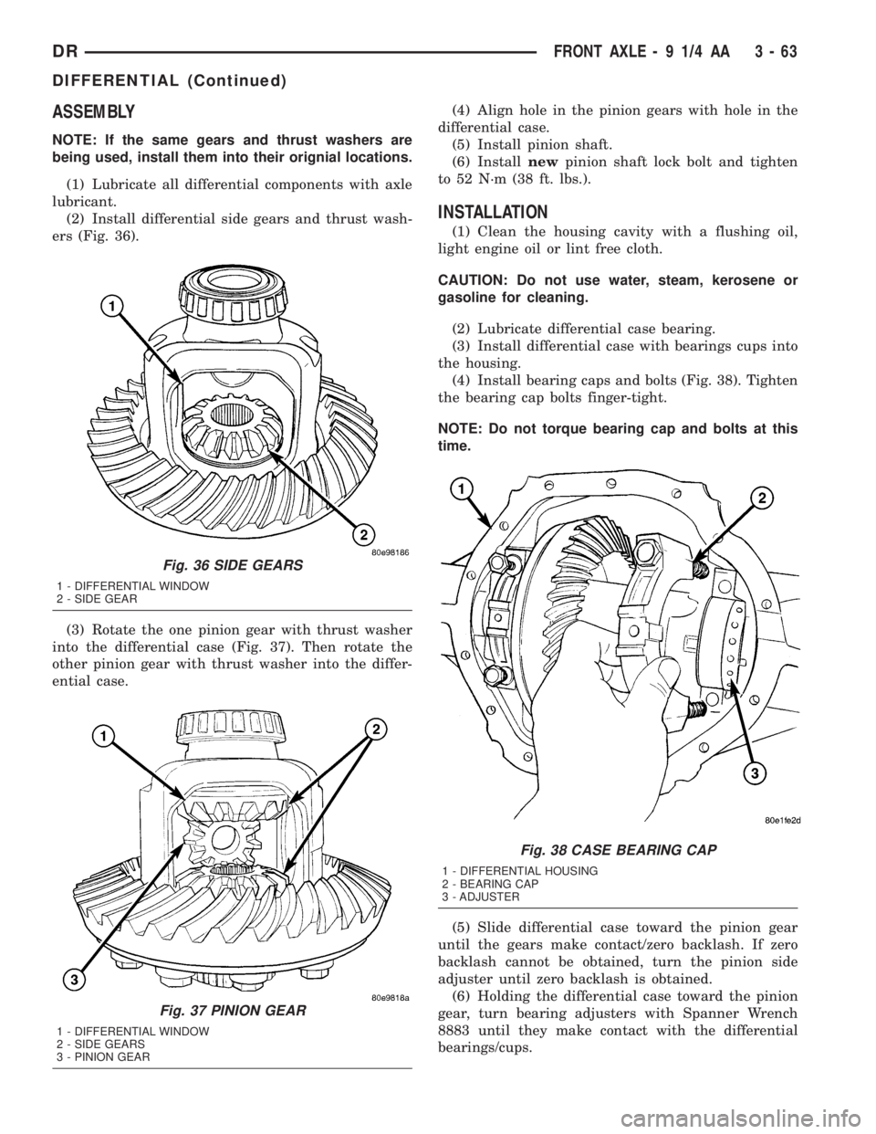
ASSEMBLY
NOTE: If the same gears and thrust washers are
being used, install them into their orignial locations.
(1) Lubricate all differential components with axle
lubricant.
(2) Install differential side gears and thrust wash-
ers (Fig. 36).
(3) Rotate the one pinion gear with thrust washer
into the differential case (Fig. 37). Then rotate the
other pinion gear with thrust washer into the differ-
ential case.(4) Align hole in the pinion gears with hole in the
differential case.
(5) Install pinion shaft.
(6) Installnewpinion shaft lock bolt and tighten
to 52 N´m (38 ft. lbs.).
INSTALLATION
(1) Clean the housing cavity with a flushing oil,
light engine oil or lint free cloth.
CAUTION: Do not use water, steam, kerosene or
gasoline for cleaning.
(2) Lubricate differential case bearing.
(3) Install differential case with bearings cups into
the housing.
(4) Install bearing caps and bolts (Fig. 38). Tighten
the bearing cap bolts finger-tight.
NOTE: Do not torque bearing cap and bolts at this
time.
(5) Slide differential case toward the pinion gear
until the gears make contact/zero backlash. If zero
backlash cannot be obtained, turn the pinion side
adjuster until zero backlash is obtained.
(6) Holding the differential case toward the pinion
gear, turn bearing adjusters with Spanner Wrench
8883 until they make contact with the differential
bearings/cups.
Fig. 36 SIDE GEARS
1 - DIFFERENTIAL WINDOW
2 - SIDE GEAR
Fig. 37 PINION GEAR
1 - DIFFERENTIAL WINDOW
2 - SIDE GEARS
3 - PINION GEAR
Fig. 38 CASE BEARING CAP
1 - DIFFERENTIAL HOUSING
2 - BEARING CAP
3 - ADJUSTER
DRFRONT AXLE - 9 1/4 AA 3 - 63
DIFFERENTIAL (Continued)
Page 160 of 2895

(2) Remove differential cover and drain the lubri-
cant.
(3) Clean housing cavity with flushing oil, light
engine oil or a lint free cloth.
NOTE: Do not use steam, kerosene or gasoline to
clean the housing.
(4) Remove axle shafts.
(5) Remove RWAL/ABS sensor from housing.
NOTE: Side play resulting from bearing races being
loose on case hubs requires replacement of the dif-
ferential case.
(6) Mark differential housing and bearing caps for
installation reference (Fig. 30).(7) Remove bearing threaded adjuster lock from
each bearing cap.
(8) Loosen differential bearing cap bolts.
(9) Loosen differential bearing adjusters through
the axle tubes with Wrench C-4164 (Fig. 31).
(10) Hold differential case while removing bearing
caps and adjusters.
(11) Remove differential case.
NOTE: Tag the differential bearing cups and
threaded adjusters to indicate their location.
Fig. 28 DIFFERENTIAL-STRAIGHT AHEAD DRIVING
1 - IN STRAIGHT AHEAD DRIVING EACH WHEEL ROTATES AT
100% OF CASE SPEED
2 - PINION GEAR
3 - SIDE GEAR
4 - PINION GEARS ROTATE WITH CASE
Fig. 29 DIFFERENTIAL-ON TURNS
1 - PINION GEARS ROTATE ON PINION SHAFT
Fig. 30 REFERENCE MARKS
1 - REFERENCE MARKS
2 - REFERENCE MARK
3 - BEARING CAPS
Fig. 31 THREADED ADJUSTER TOOL
1 - AXLE TUBE
2 - BACKING PLATE
3 - THREAD ADJUSTER WRENCH
DRREAR AXLE - 9 1/4 3 - 87
DIFFERENTIAL (Continued)