2003 DODGE RAM oil
[x] Cancel search: oilPage 307 of 2895
WARNING: DO NOT REMOVE OR LOOSEN THE
RADIATOR CAP WITH THE COOLING SYSTEM HOT
AND UNDER PRESSURE. SERIOUS BURNS FROM
THE COOLANT OR HIGH PRESSURE STEAM CAN
OCCUR.
For 3.7L / 4.7L/5.9L engines, remove the radiator
cap from the coolant degas bottle to add coolant.
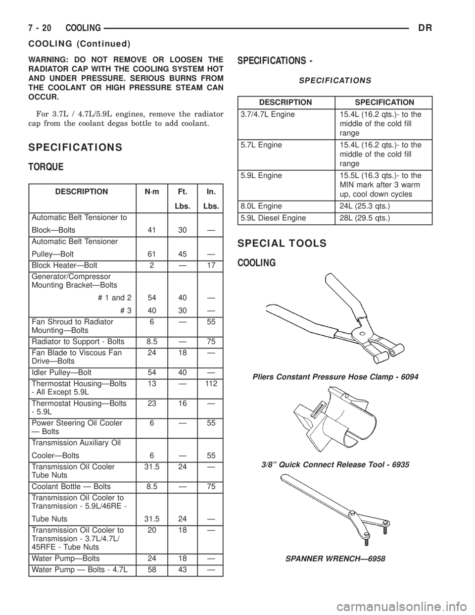
SPECIFICATIONS
TORQUE
DESCRIPTION N´m Ft. In.
Lbs. Lbs.
Automatic Belt Tensioner to
BlockÐBolts 41 30 Ð
Automatic Belt Tensioner
PulleyÐBolt 61 45 Ð
Block HeaterÐBolt 2 Ð 17
Generator/Compressor
Mounting BracketÐBolts
# 1 and 2 54 40 Ð
# 3 40 30 Ð
Fan Shroud to Radiator
MountingÐBolts6Ð55
Radiator to Support - Bolts 8.5 Ð 75
Fan Blade to Viscous Fan
DriveÐBolts24 18 Ð
Idler PulleyÐBolt 54 40 Ð
Thermostat HousingÐBolts
- All Except 5.9L13 Ð 112
Thermostat HousingÐBolts
- 5.9L23 16 Ð
Power Steering Oil Cooler
Ð Bolts6Ð55
Transmission Auxiliary Oil
CoolerÐBolts 6 Ð 55
Transmission Oil Cooler
Tube Nuts31.5 24 Ð
Coolant Bottle Ð Bolts 8.5 Ð 75
Transmission Oil Cooler to
Transmission - 5.9L/46RE -
Tube Nuts 31.5 24 Ð
Transmission Oil Cooler to
Transmission - 3.7L/4.7L/
45RFE - Tube Nuts20 18 Ð
Water PumpÐBolts 24 18 Ð
Water Pump Ð Bolts - 4.7L 58 43 Ð
SPECIFICATIONS -
SPECIFICATIONS
DESCRIPTION SPECIFICATION
3.7/4.7L Engine 15.4L (16.2 qts.)- to the
middle of the cold fill
range
5.7L Engine 15.4L (16.2 qts.)- to the
middle of the cold fill
range
5.9L Engine 15.5L (16.3 qts.)- to the
MIN mark after 3 warm
up, cool down cycles
8.0L Engine 24L (25.3 qts.)
5.9L Diesel Engine 28L (29.5 qts.)
SPECIAL TOOLS
COOLING
Pliers Constant Pressure Hose Clamp - 6094
3/8º Quick Connect Release Tool - 6935
SPANNER WRENCHÐ6958
7 - 20 COOLINGDR
COOLING (Continued)
Page 310 of 2895

NOTE: A used belt should be replaced if tensioner
indexing arrow has moved to the minimum tension
indicator. Tensioner travel stops at this point.
(1) Remove accessory drive belt (Refer to 7 -
COOLING/ACCESSORY DRIVE/DRIVE BELTS -
REMOVAL).
(2) Remove tensioner assembly from mounting
bracket (Fig. 2).
WARNING: BECAUSE OF HIGH SPRING PRES-
SURE, DO NOT ATTEMPT TO DISASSEMBLE AUTO-
MATIC TENSIONER. UNIT IS SERVICED AS AN
ASSEMBLY EXCEPT FOR PULLEY ON TENSIONER.
(3) Remove pulley bolt. Remove pulley from ten-
sioner.
INSTALLATION
(1) Install pulley and pulley bolt to tensioner.
Tighten bolt to 61 N´m (45 ft. lbs.) torque.
(2) An indexing slot is located on back of tensioner.
Align this slot to the head of the bolt on the front
cover. Install the mounting bolt. Tighten bolt to 41
N´m (30 ft. lbs.).
(3) Install accessory drive belt (Refer to 7 - COOL-
ING/ACCESSORY DRIVE/DRIVE BELTS - INSTAL-
LATION).
(4) Check belt indexing marks (Fig. 1).
BELT TENSIONERS - 5.9L
DESCRIPTION
Correct drive belt tension is required to ensure
optimum performance of the belt driven engine acces-
sories. If specified tension is not maintained, belt
slippage may cause; engine overheating, lack of
power steering assist, loss of air conditioning capac-
ity, reduced generator output rate, and greatly
reduced belt life.
It is not necessary to adjust belt tension on the
3.9L or 5.9L engines. These engines are equipped
with an automatic belt tensioner (Fig. 3). The ten-
sioner maintains correct belt tension at all times.
Due to use of this belt tensioner, do not attempt to
use a belt tension gauge on 3.9L or 5.9L engines.
OPERATION
The automatic belt tensioner maintains belt ten-
sion by using internal spring pressure, a pivoting
arm and pulley to press against the drive belt.
REMOVAL
WARNING: BECAUSE OF HIGH SPRING PRES-
SURE, DO NOT ATTEMPT TO DISASSEMBLE AUTO-
MATIC TENSIONER. UNIT IS SERVICED AS AN
ASSEMBLY (EXCEPT FOR PULLEY).
(1) Remove accessory drive belt. (Refer to 7 -
COOLING/ACCESSORY DRIVE/DRIVE BELTS -
REMOVAL).
(2) Disconnect wiring and secondary cable from
ignition coil.
(3) Remove ignition coil from coil mounting
bracket (two bolts). Do not remove coil mounting
bracket from cylinder head.
(4) Remove tensioner assembly from mounting
bracket (one nut) (Fig. 4).
Fig. 2 AUTOMATIC BELT TENSIONER - 3.7L/4.7L
ENGINE
1 - TIMING CHAIN COVER
2 - BOLT TORQUE TO 41 N´m (30 FT LBS)
3 - AUTOMATIC BELT TENSIONER
Fig. 3 Automatic Belt Tensioner - 5.9L Engines
1 - AUTOMATIC TENSIONER
2 - COIL AND BRACKET
3 - SCREW AND WASHER
DRACCESSORY DRIVE 7 - 23
BELT TENSIONERS - 3.7L / 4.7L (Continued)
Page 311 of 2895
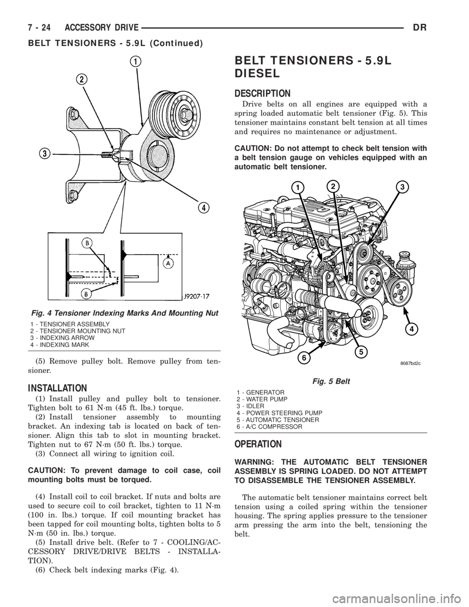
(5) Remove pulley bolt. Remove pulley from ten-
sioner.
INSTALLATION
(1) Install pulley and pulley bolt to tensioner.
Tighten bolt to 61 N´m (45 ft. lbs.) torque.
(2) Install tensioner assembly to mounting
bracket. An indexing tab is located on back of ten-
sioner. Align this tab to slot in mounting bracket.
Tighten nut to 67 N´m (50 ft. lbs.) torque.
(3) Connect all wiring to ignition coil.
CAUTION: To prevent damage to coil case, coil
mounting bolts must be torqued.
(4) Install coil to coil bracket. If nuts and bolts are
used to secure coil to coil bracket, tighten to 11 N´m
(100 in. lbs.) torque. If coil mounting bracket has
been tapped for coil mounting bolts, tighten bolts to 5
N´m (50 in. lbs.) torque.
(5) Install drive belt. (Refer to 7 - COOLING/AC-
CESSORY DRIVE/DRIVE BELTS - INSTALLA-
TION).
(6) Check belt indexing marks (Fig. 4).
BELT TENSIONERS - 5.9L
DIESEL
DESCRIPTION
Drive belts on all engines are equipped with a
spring loaded automatic belt tensioner (Fig. 5). This
tensioner maintains constant belt tension at all times
and requires no maintenance or adjustment.
CAUTION: Do not attempt to check belt tension with
a belt tension gauge on vehicles equipped with an
automatic belt tensioner.
OPERATION
WARNING: THE AUTOMATIC BELT TENSIONER
ASSEMBLY IS SPRING LOADED. DO NOT ATTEMPT
TO DISASSEMBLE THE TENSIONER ASSEMBLY.
The automatic belt tensioner maintains correct belt
tension using a coiled spring within the tensioner
housing. The spring applies pressure to the tensioner
arm pressing the arm into the belt, tensioning the
belt.
Fig. 4 Tensioner Indexing Marks And Mounting Nut
1 - TENSIONER ASSEMBLY
2 - TENSIONER MOUNTING NUT
3 - INDEXING ARROW
4 - INDEXING MARK
Fig. 5 Belt
1 - GENERATOR
2 - WATER PUMP
3 - IDLER
4 - POWER STEERING PUMP
5 - AUTOMATIC TENSIONER
6 - A/C COMPRESSOR
7 - 24 ACCESSORY DRIVEDR
BELT TENSIONERS - 5.9L (Continued)
Page 313 of 2895
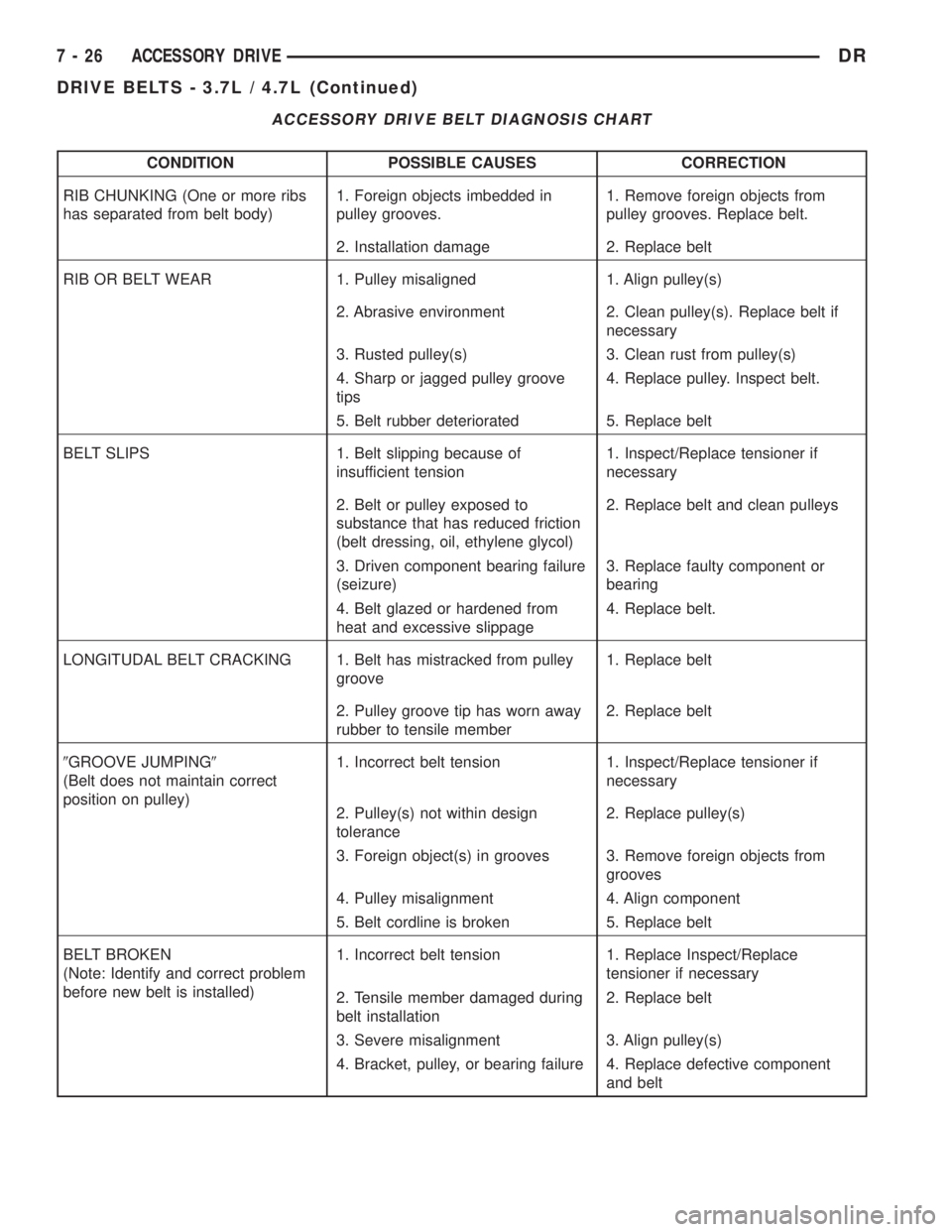
ACCESSORY DRIVE BELT DIAGNOSIS CHART
CONDITION POSSIBLE CAUSES CORRECTION
RIB CHUNKING (One or more ribs
has separated from belt body)1. Foreign objects imbedded in
pulley grooves.1. Remove foreign objects from
pulley grooves. Replace belt.
2. Installation damage 2. Replace belt
RIB OR BELT WEAR 1. Pulley misaligned 1. Align pulley(s)
2. Abrasive environment 2. Clean pulley(s). Replace belt if
necessary
3. Rusted pulley(s) 3. Clean rust from pulley(s)
4. Sharp or jagged pulley groove
tips4. Replace pulley. Inspect belt.
5. Belt rubber deteriorated 5. Replace belt
BELT SLIPS 1. Belt slipping because of
insufficient tension1. Inspect/Replace tensioner if
necessary
2. Belt or pulley exposed to
substance that has reduced friction
(belt dressing, oil, ethylene glycol)2. Replace belt and clean pulleys
3. Driven component bearing failure
(seizure)3. Replace faulty component or
bearing
4. Belt glazed or hardened from
heat and excessive slippage4. Replace belt.
LONGITUDAL BELT CRACKING 1. Belt has mistracked from pulley
groove1. Replace belt
2. Pulley groove tip has worn away
rubber to tensile member2. Replace belt
9GROOVE JUMPING9
(Belt does not maintain correct
position on pulley)1. Incorrect belt tension 1. Inspect/Replace tensioner if
necessary
2. Pulley(s) not within design
tolerance2. Replace pulley(s)
3. Foreign object(s) in grooves 3. Remove foreign objects from
grooves
4. Pulley misalignment 4. Align component
5. Belt cordline is broken 5. Replace belt
BELT BROKEN
(Note: Identify and correct problem
before new belt is installed)1. Incorrect belt tension 1. Replace Inspect/Replace
tensioner if necessary
2. Tensile member damaged during
belt installation2. Replace belt
3. Severe misalignment 3. Align pulley(s)
4. Bracket, pulley, or bearing failure 4. Replace defective component
and belt
7 - 26 ACCESSORY DRIVEDR
DRIVE BELTS - 3.7L / 4.7L (Continued)
Page 316 of 2895
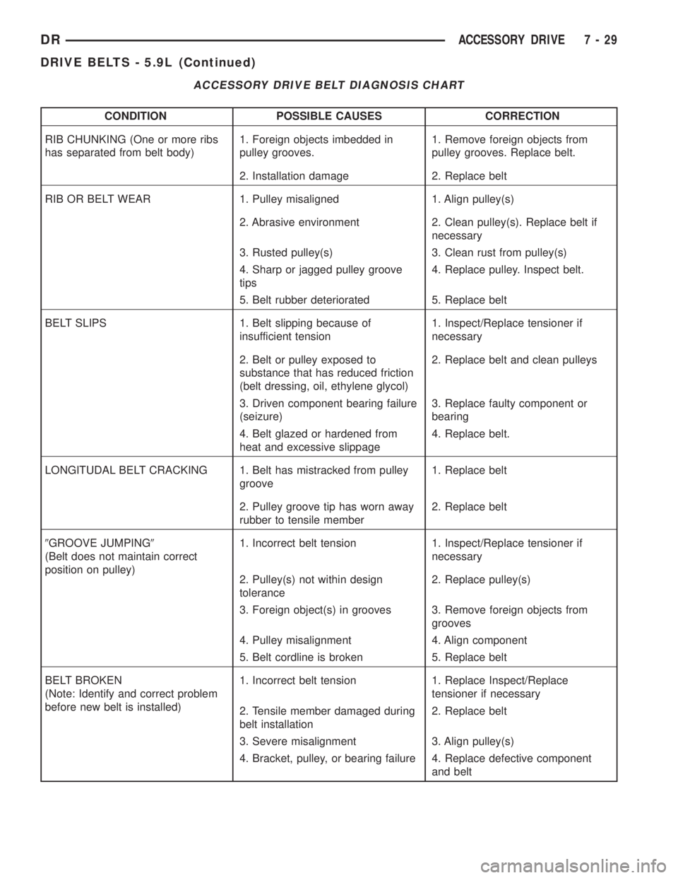
ACCESSORY DRIVE BELT DIAGNOSIS CHART
CONDITION POSSIBLE CAUSES CORRECTION
RIB CHUNKING (One or more ribs
has separated from belt body)1. Foreign objects imbedded in
pulley grooves.1. Remove foreign objects from
pulley grooves. Replace belt.
2. Installation damage 2. Replace belt
RIB OR BELT WEAR 1. Pulley misaligned 1. Align pulley(s)
2. Abrasive environment 2. Clean pulley(s). Replace belt if
necessary
3. Rusted pulley(s) 3. Clean rust from pulley(s)
4. Sharp or jagged pulley groove
tips4. Replace pulley. Inspect belt.
5. Belt rubber deteriorated 5. Replace belt
BELT SLIPS 1. Belt slipping because of
insufficient tension1. Inspect/Replace tensioner if
necessary
2. Belt or pulley exposed to
substance that has reduced friction
(belt dressing, oil, ethylene glycol)2. Replace belt and clean pulleys
3. Driven component bearing failure
(seizure)3. Replace faulty component or
bearing
4. Belt glazed or hardened from
heat and excessive slippage4. Replace belt.
LONGITUDAL BELT CRACKING 1. Belt has mistracked from pulley
groove1. Replace belt
2. Pulley groove tip has worn away
rubber to tensile member2. Replace belt
9GROOVE JUMPING9
(Belt does not maintain correct
position on pulley)1. Incorrect belt tension 1. Inspect/Replace tensioner if
necessary
2. Pulley(s) not within design
tolerance2. Replace pulley(s)
3. Foreign object(s) in grooves 3. Remove foreign objects from
grooves
4. Pulley misalignment 4. Align component
5. Belt cordline is broken 5. Replace belt
BELT BROKEN
(Note: Identify and correct problem
before new belt is installed)1. Incorrect belt tension 1. Replace Inspect/Replace
tensioner if necessary
2. Tensile member damaged during
belt installation2. Replace belt
3. Severe misalignment 3. Align pulley(s)
4. Bracket, pulley, or bearing failure 4. Replace defective component
and belt
DRACCESSORY DRIVE 7 - 29
DRIVE BELTS - 5.9L (Continued)
Page 319 of 2895
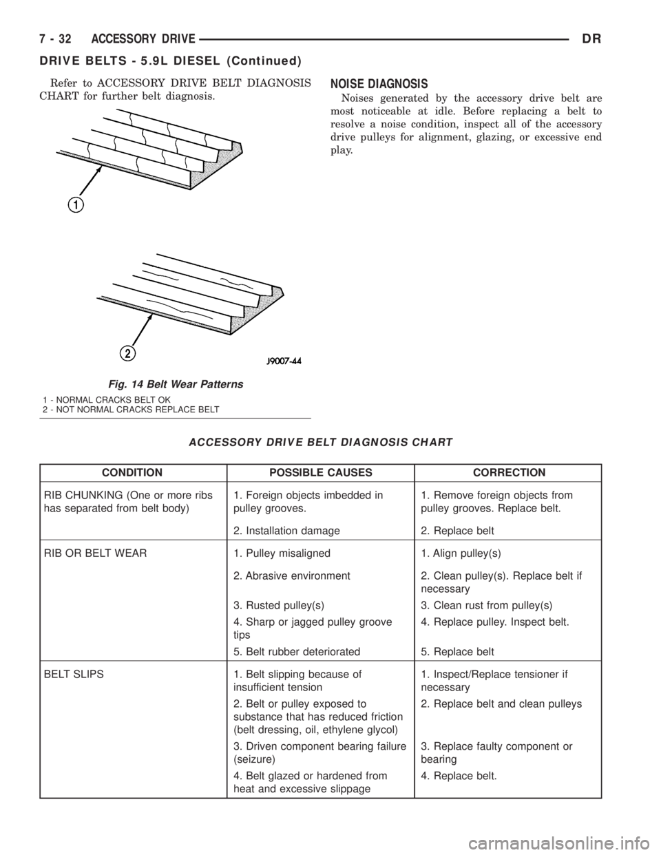
Refer to ACCESSORY DRIVE BELT DIAGNOSIS
CHART for further belt diagnosis.NOISE DIAGNOSIS
Noises generated by the accessory drive belt are
most noticeable at idle. Before replacing a belt to
resolve a noise condition, inspect all of the accessory
drive pulleys for alignment, glazing, or excessive end
play.
ACCESSORY DRIVE BELT DIAGNOSIS CHART
CONDITION POSSIBLE CAUSES CORRECTION
RIB CHUNKING (One or more ribs
has separated from belt body)1. Foreign objects imbedded in
pulley grooves.1. Remove foreign objects from
pulley grooves. Replace belt.
2. Installation damage 2. Replace belt
RIB OR BELT WEAR 1. Pulley misaligned 1. Align pulley(s)
2. Abrasive environment 2. Clean pulley(s). Replace belt if
necessary
3. Rusted pulley(s) 3. Clean rust from pulley(s)
4. Sharp or jagged pulley groove
tips4. Replace pulley. Inspect belt.
5. Belt rubber deteriorated 5. Replace belt
BELT SLIPS 1. Belt slipping because of
insufficient tension1. Inspect/Replace tensioner if
necessary
2. Belt or pulley exposed to
substance that has reduced friction
(belt dressing, oil, ethylene glycol)2. Replace belt and clean pulleys
3. Driven component bearing failure
(seizure)3. Replace faulty component or
bearing
4. Belt glazed or hardened from
heat and excessive slippage4. Replace belt.
Fig. 14 Belt Wear Patterns
1 - NORMAL CRACKS BELT OK
2 - NOT NORMAL CRACKS REPLACE BELT
7 - 32 ACCESSORY DRIVEDR
DRIVE BELTS - 5.9L DIESEL (Continued)
Page 323 of 2895
WATER PUMP - 5.9L
DESCRIPTION.........................62
OPERATION...........................62
DIAGNOSIS AND TESTINGÐWATER PUMP . . . 62
REMOVAL.............................63
CLEANING............................64
INSPECTION..........................64
INSTALLATION.........................64
WATER PUMP - 3.7L/4.7L
DESCRIPTION
DESCRIPTIONÐWATER PUMP...........64
DESCRIPTIONÐWATER PUMP BYPASS....64
OPERATION
OPERATIONÐWATER PUMP............64
OPERATIONÐWATER PUMP BYPASS.....65
REMOVAL.............................65
CLEANING............................66
INSPECTION..........................66
INSTALLATION.........................66
WATER PUMP - 5.9L DIESEL
DESCRIPTION.........................67OPERATION...........................67
DIAGNOSIS AND TESTINGÐWATER PUMP . . . 67
REMOVAL.............................67
CLEANING............................67
INSPECTION..........................68
INSTALLATION.........................68
WATER PUMP INLET TUBE - 5.9L
REMOVAL
REMOVAL - WATER PUMP BYPASS HOSE
WITH AIR CONDITIONING...............68
REMOVAL - WATER PUMP BYPASS HOSE
WITHOUT AIR CONDITIONING...........69
INSTALLATION
INSTALLATION - WATER PUMP BYPASS
HOSE WITH AIR CONDITIONING.........70
INSTALLATION - WATER PUMP BYPASS
HOSE WITHOUT AIR CONDITIONING......70
WATER PUMP - 5.7L
REMOVAL.............................70
INSTALLATION.........................71
COOLANT
DESCRIPTION
DESCRIPTION - ENGINE COOLANT
ETHYLENE-GLYCOL MIXTURES
CAUTION: Richer antifreeze mixtures cannot be
measured with normal field equipment and can
cause problems associated with 100 percent ethyl-
ene-glycol.
The use of aluminum cylinder blocks, cylinder
heads and water pumps requires special corrosion
protection. Only MopartAntifreeze/Coolant, 5 year/
100,000Mil;e Formula (ethylene-glycol base coolant
with corrosion inhibitors called HOAT, for Hybrid
Additive Technology) is recommended. This coolant
offers the best engine cooling without corrosion when
mixed with 50% distilled water to obtain a freeze
point of -37ÉC (-35ÉF).
The required ethylene-glycol (antifreeze) and water
mixture depends upon the climate and vehicle oper-
ating conditions. The antifreeze concentrationmust
alwaysbe a minimum of 44 percent, year-round in
all climates.If percentage is lower than 44 per-
cent, engine parts may be eroded by cavitation,
and cooling system components may be
severely damaged by corrosion.Maximum protec-
tion against freezing is provided with a 68% anti-
freeze concentration, which prevents freezing down to-67.7É C (-90É F). A higher percentage will freeze at a
warmer temperature. Also, a higher percentage of
antifreeze can cause the engine to overheat because
the specific heat of antifreeze is lower than that of
water.
Use of 100 percent ethylene-glycol will cause for-
mation of additive deposits in the system, as the cor-
rosion inhibitive additives in ethylene-glycol require
the presence of water to dissolve. The deposits act as
insulation, causing temperatures to rise to as high as
149É C (300É F). This temperature is hot enough to
melt plastic and soften solder. The increased temper-
ature can result in engine detonation. In addition,
100 percent ethylene-glycol freezes at 22É C (-8É F ).
PROPYLENE-GLYCOL MIXTURES
It's overall effective temperature range is smaller
than that of ethylene-glycol. The freeze point of 50/50
propylene-glycol and water is -32É C (-26É F). 5É C
higher than ethylene-glycol's freeze point. The boiling
point (protection against summer boil-over) of propy-
lene-glycol is 125É C (257ÉF)at96.5 kPa (14 psi),
compared to 128É C (263É F) for ethylene-glycol. Use
of propylene-glycol can result in boil-over or freeze-up
on a cooling system designed for ethylene-glycol. Pro-
pylene glycol also has poorer heat transfer character-
istics than ethylene glycol. This can increase cylinder
head temperatures under certain conditions.
Propylene-glycol/ethylene-glycol Mixtures can
cause the destabilization of various corrosion inhibi-
tors, causing damage to the various cooling system
7 - 36 ENGINEDR
Page 325 of 2895
CAUTION: Do not use coolant additives that are
claimed to improve engine cooling.
OPERATION
Coolant flows through the engine block absorbing
the heat from the engine, then flows to the radiator
where the cooling fins in the radiator transfers the
heat from the coolant to the atmosphere. During cold
weather the ethylene-glycol or propylene-glycol cool-
ant prevents water present in the cooling system
from freezing within temperatures indicated by mix-
ture ratio of coolant to water.
COOLANT RECOVERY
CONTAINER-5.9L
DESCRIPTION
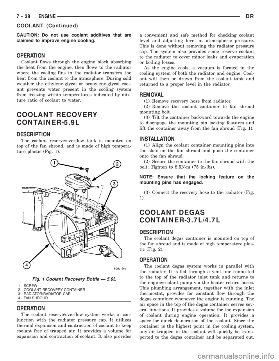
The coolant reserve/overflow tank is mounted on
top of the fan shroud, and is made of high tempera-
ture plastic (Fig. 1).
OPERATION
The coolant reserve/overflow system works in con-
junction with the radiator pressure cap. It utilizes
thermal expansion and contraction of coolant to keep
coolant free of trapped air. It provides a volume for
expansion and contraction of coolant. It also providesa convenient and safe method for checking coolant
level and adjusting level at atmospheric pressure.
This is done without removing the radiator pressure
cap. The system also provides some reserve coolant
to the radiator to cover minor leaks and evaporation
or boiling losses.
As the engine cools, a vacuum is formed in the
cooling system of both the radiator and engine. Cool-
ant will then be drawn from the coolant tank and
returned to a proper level in the radiator.
REMOVAL
(1) Remove recovery hose from radiator.
(2) Remove the coolant container to fan shroud
mounting bolt.
(3) Tilt the container backward towards the engine
to disengage the mounting pin locking features and
lift the container away from the fan shroud (Fig. 1).
INSTALLATION
(1) Align the coolant container mounting pins into
the slots on the fan shroud and push the container
onto the fan shroud.
(2) Secure the container to the fan shroud with the
bolt. Tighten to 8.5N´m (75 in-lbs).
NOTE: Ensure that the locking feature on the
mounting pins has engaged.
(3) Connect the recovery hose to the radiator (Fig.
1).
COOLANT DEGAS
CONTAINER-3.7L/4.7L
DESCRIPTION
The coolant degas container is mounted on top of
the fan shroud and is made of high temperatyre plas-
tic (Fig. 2).
OPERATION
The coolant degas system works in parallel with
the radiator. It is fed through a vent line connected
to the top of the radiator inlet tank and returns to
the engine/coolant pump via the heater return hoses.
This plumbing arrangement, together with the inlet
thermostat, provides for constant flow through the
degas container whenever the engine is running. The
air space in the top of the degas container serves sev-
eral functions. It provides a volume for the expansion
of coolant during engine operation. It provides a
space for quick de-aeration of the coolant. Since the
container is the highest point in the cooling system,
any air trapped in the coolant will quickly be trans-
ported to the degas container and be separated out.
Fig. 1 Coolant Recovery Bottle Ð 5.9L
1 - SCREW
2 - COOLANT RECOVERY CONTAINER
3 - RADIATOR/RADIATOR CAP
4 - FAN SHROUD
7 - 38 ENGINEDR
COOLANT (Continued)