2003 DODGE RAM Heating and air conditioning blower controls
[x] Cancel search: Heating and air conditioning blower controlsPage 2781 of 2895
If the floor outlet air temperature is too low, refer
to Cooling to check the engine coolant temperature
specifications. Both of the heater hoses should be hot
to the touch. The coolant return heater hose should
be slightly cooler than the coolant supply heater
hose. If the return hose is much cooler than the sup-
ply hose, locate and repair the engine coolant flow
obstruction in the cooling system. Refer to Cooling
for the procedures.
An alternate method of checking heater perfor-
mance is to use a DRBIIItscan tool to monitor the
engine coolant temperature. The floor outlet air tem-
perature reading should be no more than 4.5É C (40É
F) lower than the engine coolant temperature read-
ing.
OBSTRUCTED COOLANT FLOW Possible loca-
tions or causes of obstructed coolant flow:
²Faulty water pump.
²Faulty thermostat.
²Pinched or kinked heater hoses.
²Improper heater hose routing.
²Plugged heater hoses or supply and return ports
at the cooling system connections.
²A plugged heater core.If proper coolant flow through the cooling system is
verified, and heater outlet air temperature is still
low, a mechanical problem may exist.
MECHANICAL PROBLEMS Possible locations or
causes of insufficient heat:
²An obstructed cowl air intake.
²Obstructed heater system outlets.
²A faulty, obstructed or improperly installed
blend door.
²A faulty blower system.
²A faulty a/c heater control.
TEMPERATURE CONTROL
If the heater outlet air temperature cannot be
adjusted with the temperature control knob on the
a/c heater control panel, the following could require
service:
²A faulty a/c heater control.
²A faulty blend door actuator.
²A faulty, obstructed or improperly installed
blend door.
²An obstructed cowl air intake.
²The engine cooling system.
Heater Diagnosis
CONDITION POSSIBLE CAUSE CORRECTION
INSUFFICIENT HEATER
OUTPUT.1. Incorrect engine
coolant level.1. Check the engine coolant level. Refer to Cooling for
the procedures.
2. Air trapped in engine
cooling system.2. Check the operation of the coolant reserve/recovery
system. Refer to Cooling for the procedures.
3. Incorrect engine
coolant temperature.3. Check the performance and operation of the engine
cooling system including: thermostat, water pump, fan
drive, accessory drive belt, coolant flow (plugged radiator
or heater core, plugged or kinked coolant hoses), air flow
(missing or improperly installed radiator air seals or fan
shroud). Refer to Cooling for the procedures.
4. Blend door actuator
inoperative or defective.4. (Refer to Controls/Blend Door Actuator) in this group.
5. Blend door not
operating properly.5. Check for a damaged, obstructed or improperly
installed blend door or seals. (Refer to Controls/Blend
Door Actuator) in this group.
6. Insufficient air flow
through heater housing.6. Remove foreign material or obstructions from cowl air
intake.
7. Improper blower motor
operation.7. (Refer to Distribution/Blower Motor/ Diagnosis and
Testing) in this group.
24 - 6 HEATING & AIR CONDITIONINGDR
HEATING & AIR CONDITIONING (Continued)
Page 2792 of 2895
trol module learns the blend air door stop positions
during the calibration procedure and will store a
Diagnostic Trouble Code (DTC) for any problems it
detects in the blend door actuator circuits. The blend
door actuator can be diagnosed using a DRBIIItscan
tool. Refer to the appropriate diagnostic information.
REMOVAL
The single zone heating and air conditioning sys-
tem is equipped with a single blend door actuator.
The dual zone system has two blend door actuators,
one for the driver side blend air door and one for the
passenger side blend air door. The same service pro-
cedures can be used for each of these actuators.
WARNING: ON VEHICLES EQUIPPED WITH AIR-
BAGS, DISABLE THE AIRBAG SYSTEM BEFORE
ATTEMPTING ANY STEERING WHEEL, STEERING
COLUMN, OR INSTRUMENT PANEL COMPONENT
DIAGNOSIS OR SERVICE. DISCONNECT AND ISO-
LATE THE BATTERY NEGATIVE (GROUND) CABLE,
THEN WAIT TWO MINUTES FOR THE AIRBAG SYS-
TEM CAPACITOR TO DISCHARGE BEFORE PER-
FORMING FURTHER DIAGNOSIS OR SERVICE. THIS
IS THE ONLY SURE WAY TO DISABLE THE AIRBAG
SYSTEM. FAILURE TO TAKE THE PROPER PRE-
CAUTIONS COULD RESULT IN ACCIDENTAL AIR-
BAG DEPLOYMENT AND POSSIBLE PERSONAL
INJURY.
(1) Disconnect and isolate the battery negative
cable.
(2) Remove the instrument panel assembly(Refer
to 23 - BODY/INSTRUMENT PANEL/INSTRUMENT
PANEL ASSEMBLY - REMOVAL).
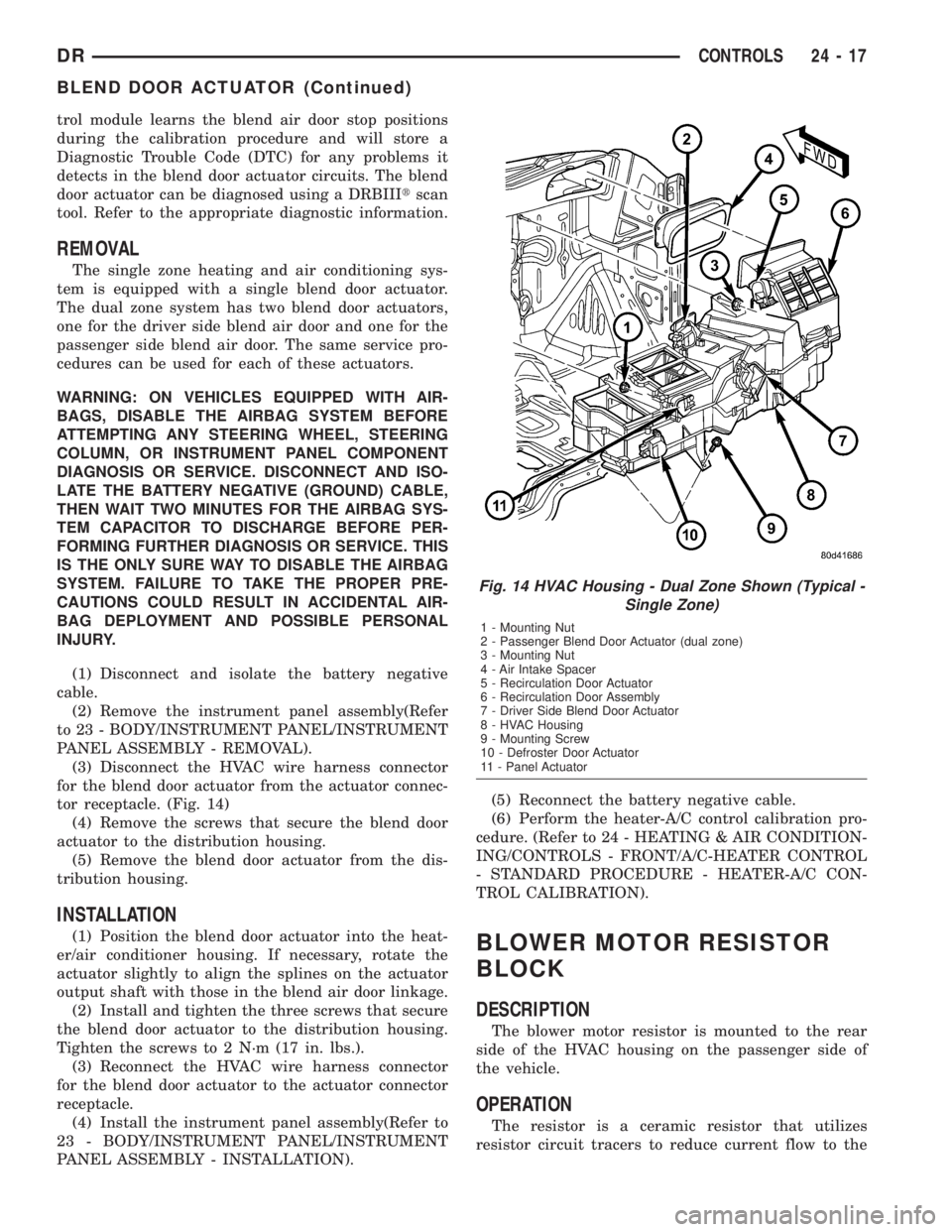
(3) Disconnect the HVAC wire harness connector
for the blend door actuator from the actuator connec-
tor receptacle. (Fig. 14)
(4) Remove the screws that secure the blend door
actuator to the distribution housing.
(5) Remove the blend door actuator from the dis-
tribution housing.
INSTALLATION
(1) Position the blend door actuator into the heat-
er/air conditioner housing. If necessary, rotate the
actuator slightly to align the splines on the actuator
output shaft with those in the blend air door linkage.
(2) Install and tighten the three screws that secure
the blend door actuator to the distribution housing.
Tighten the screws to 2 N´m (17 in. lbs.).
(3) Reconnect the HVAC wire harness connector
for the blend door actuator to the actuator connector
receptacle.
(4) Install the instrument panel assembly(Refer to
23 - BODY/INSTRUMENT PANEL/INSTRUMENT
PANEL ASSEMBLY - INSTALLATION).(5) Reconnect the battery negative cable.
(6) Perform the heater-A/C control calibration pro-
cedure. (Refer to 24 - HEATING & AIR CONDITION-
ING/CONTROLS - FRONT/A/C-HEATER CONTROL
- STANDARD PROCEDURE - HEATER-A/C CON-
TROL CALIBRATION).BLOWER MOTOR RESISTOR
BLOCK
DESCRIPTION
The blower motor resistor is mounted to the rear
side of the HVAC housing on the passenger side of
the vehicle.
OPERATION
The resistor is a ceramic resistor that utilizes
resistor circuit tracers to reduce current flow to the
Fig. 14 HVAC Housing - Dual Zone Shown (Typical -
Single Zone)
1 - Mounting Nut
2 - Passenger Blend Door Actuator (dual zone)
3 - Mounting Nut
4 - Air Intake Spacer
5 - Recirculation Door Actuator
6 - Recirculation Door Assembly
7 - Driver Side Blend Door Actuator
8 - HVAC Housing
9 - Mounting Screw
10 - Defroster Door Actuator
11 - Panel Actuator
DRCONTROLS 24 - 17
BLEND DOOR ACTUATOR (Continued)
Page 2794 of 2895
WARNING: ON VEHICLES EQUIPPED WITH AIR-
BAGS, DISABLE THE AIRBAG SYSTEM BEFORE
ATTEMPTING ANY STEERING WHEEL, STEERING
COLUMN, OR INSTRUMENT PANEL COMPONENT
DIAGNOSIS OR SERVICE. DISCONNECT AND ISO-
LATE THE BATTERY NEGATIVE (GROUND) CABLE,
THEN WAIT TWO MINUTES FOR THE AIRBAG SYS-
TEM CAPACITOR TO DISCHARGE BEFORE PER-
FORMING FURTHER DIAGNOSIS OR SERVICE. THIS
IS THE ONLY SURE WAY TO DISABLE THE AIRBAG
SYSTEM. FAILURE TO TAKE THE PROPER PRE-
CAUTIONS COULD RESULT IN AN ACCIDENTAL
AIRBAG DEPLOYMENT AND POSSIBLE PERSONAL
INJURY.
(1) Check for battery voltage at the fuse in the
Power Distribution Center (PDC). If OK, go to Step
2. If not OK, repair the shorted circuit or component
as required and replace the faulty fuse.
(2) Turn the ignition switch to the Off position.
Disconnect and isolate the battery negative cable.
Remove the A/C Heater control from the instrument
panel. Check for continuity between the ground cir-
cuit cavity of the A/C Heater control wire harness
connector and a good ground. There should be conti-
nuity. If OK, go to Step 3. If not OK, repair the open
circuit to ground as required.
(3) With the A/C Heater control wire harness con-
nector unplugged, place the A/C Heater mode control
switch knob in any position except the Off position.
Check for continuity between the ground circuit ter-
minal and each of the blower motor driver circuit ter-
minals of the A/C Heater control as you move the
blower motor switch knob to each of the four speed
positions. There should be continuity at each driver
circuit terminal in only one blower motor switch
speed position. If OK, test and repair the blower
driver circuits between the A/C Heater control con-
nector and the blower motor resistor as required. If
not OK, replace the faulty A/C Heater control unit.
REMOVAL
WARNING: ON VEHICLES EQUIPPED WITH AIR-
BAGS, DISABLE THE AIRBAG SYSTEM BEFORE
ATTEMPTING ANY STEERING WHEEL, STEERING
COLUMN, OR INSTRUMENT PANEL COMPONENT
DIAGNOSIS OR SERVICE. DISCONNECT AND ISO-
LATE THE BATTERY NEGATIVE (GROUND) CABLE,
THEN WAIT TWO MINUTES FOR THE AIRBAG SYS-
TEM CAPACITOR TO DISCHARGE BEFORE PER-
FORMING FURTHER DIAGNOSIS OR SERVICE. THIS
IS THE ONLY SURE WAY TO DISABLE THE AIRBAG
SYSTEM. FAILURE TO TAKE THE PROPER PRE-
CAUTIONS COULD RESULT IN AN ACCIDENTAL
AIRBAG DEPLOYMENT AND POSSIBLE PERSONAL
INJURY.The blower motor switch cannot be repaired and, if
faulty or damaged, the entire A/C Heater control unit
must be replaced. (Refer to 24 - HEATING & AIR
CONDITIONING/CONTROLS/A/C HEATER CON-
TROL - REMOVAL)
INSTALLATION
WARNING: ON VEHICLES EQUIPPED WITH AIR-
BAGS, DISABLE THE AIRBAG SYSTEM BEFORE
ATTEMPTING ANY STEERING WHEEL, STEERING
COLUMN, OR INSTRUMENT PANEL COMPONENT
DIAGNOSIS OR SERVICE. DISCONNECT AND ISO-
LATE THE BATTERY NEGATIVE (GROUND) CABLE,
THEN WAIT TWO MINUTES FOR THE AIRBAG SYS-
TEM CAPACITOR TO DISCHARGE BEFORE PER-
FORMING FURTHER DIAGNOSIS OR SERVICE. THIS
IS THE ONLY SURE WAY TO DISABLE THE AIRBAG
SYSTEM. FAILURE TO TAKE THE PROPER PRE-
CAUTIONS COULD RESULT IN AN ACCIDENTAL
AIRBAG DEPLOYMENT AND POSSIBLE PERSONAL
INJURY.
(1) The blower motor switch cannot be repaired
and, if faulty or damaged the entire A/C heater con-
trol unit must be replaced(Refer to 24 - HEATING &
AIR CONDITIONING/CONTROLS/A/C HEATER
CONTROL - INSTALLATION).
DEFROST DOOR ACTUATOR
REMOVAL - FLOOR - DEFROST DOOR
ACTUATOR
WARNING: ON VEHICLES EQUIPPED WITH AIR-
BAGS, DISABLE THE AIRBAG SYSTEM BEFORE
ATTEMPTING ANY STEERING WHEEL, STEERING
COLUMN, OR INSTRUMENT PANEL COMPONENT
DIAGNOSIS OR SERVICE. DISCONNECT AND ISO-
LATE THE BATTERY NEGATIVE (GROUND) CABLE,
THEN WAIT TWO MINUTES FOR THE AIRBAG SYS-
TEM CAPACITOR TO DISCHARGE BEFORE PER-
FORMING FURTHER DIAGNOSIS OR SERVICE. THIS
IS THE ONLY SURE WAY TO DISABLE THE AIRBAG
SYSTEM. FAILURE TO TAKE THE PROPER PRE-
CAUTIONS COULD RESULT IN AN ACCIDENTAL
AIRBAG DEPLOYMENT AND POSSIBLE PERSONAL
INJURY.
(1) Disconnect and isolate the battery negative
cable.
(2) Remove the instrument panel assembly from
the vehicle(Refer to 23 - BODY/INSTRUMENT
PANEL - REMOVAL).
(3) Remove the electrical connector from the actua-
tor (Fig. 15).
DRCONTROLS 24 - 19
BLOWER MOTOR SWITCH (Continued)
Page 2800 of 2895
(1) Recover refrigerant(Refer to 24 - HEATING &
AIR CONDITIONING/PLUMBING - STANDARD
PROCEDURE).
(2) Remove and disassemble the HVAC housing.
(Refer to 24 - HEATING & AIR CONDITIONING/
DISTRIBUTION/HVAC HOUSING - REMOVAL)
(Refer to 24 - HEATING & AIR CONDITIONING/
DISTRIBUTION/HVAC HOUSING - DISASSEMBLY)
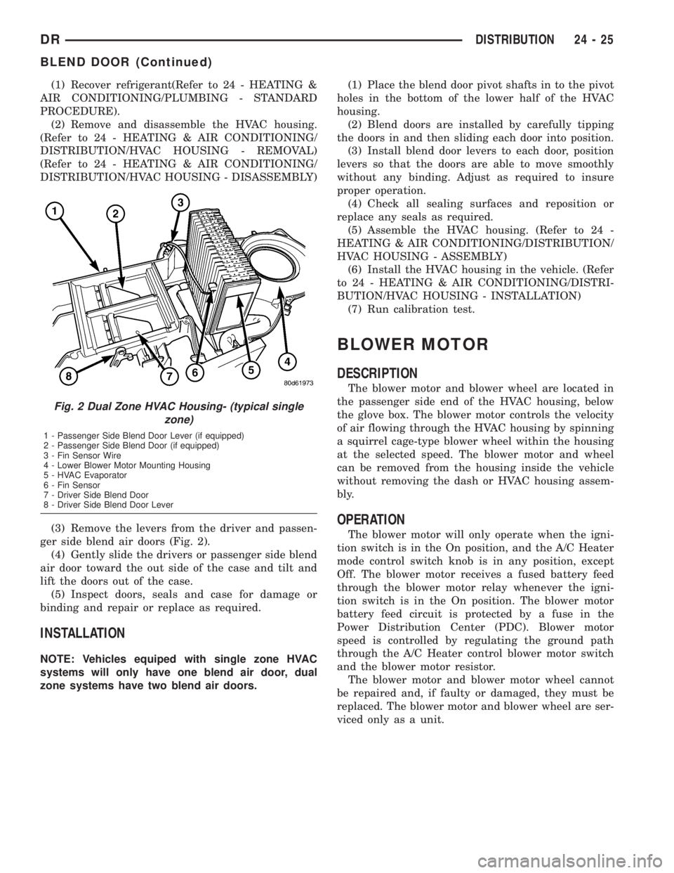
(3) Remove the levers from the driver and passen-
ger side blend air doors (Fig. 2).
(4) Gently slide the drivers or passenger side blend
air door toward the out side of the case and tilt and
lift the doors out of the case.
(5) Inspect doors, seals and case for damage or
binding and repair or replace as required.
INSTALLATION
NOTE: Vehicles equiped with single zone HVAC
systems will only have one blend air door, dual
zone systems have two blend air doors.(1) Place the blend door pivot shafts in to the pivot
holes in the bottom of the lower half of the HVAC
housing.
(2) Blend doors are installed by carefully tipping
the doors in and then sliding each door into position.
(3) Install blend door levers to each door, position
levers so that the doors are able to move smoothly
without any binding. Adjust as required to insure
proper operation.
(4) Check all sealing surfaces and reposition or
replace any seals as required.
(5) Assemble the HVAC housing. (Refer to 24 -
HEATING & AIR CONDITIONING/DISTRIBUTION/
HVAC HOUSING - ASSEMBLY)
(6) Install the HVAC housing in the vehicle. (Refer
to 24 - HEATING & AIR CONDITIONING/DISTRI-
BUTION/HVAC HOUSING - INSTALLATION)
(7) Run calibration test.
BLOWER MOTOR
DESCRIPTION
The blower motor and blower wheel are located in
the passenger side end of the HVAC housing, below
the glove box. The blower motor controls the velocity
of air flowing through the HVAC housing by spinning
a squirrel cage-type blower wheel within the housing
at the selected speed. The blower motor and wheel
can be removed from the housing inside the vehicle
without removing the dash or HVAC housing assem-
bly.
OPERATION
The blower motor will only operate when the igni-
tion switch is in the On position, and the A/C Heater
mode control switch knob is in any position, except
Off. The blower motor receives a fused battery feed
through the blower motor relay whenever the igni-
tion switch is in the On position. The blower motor
battery feed circuit is protected by a fuse in the
Power Distribution Center (PDC). Blower motor
speed is controlled by regulating the ground path
through the A/C Heater control blower motor switch
and the blower motor resistor.
The blower motor and blower motor wheel cannot
be repaired and, if faulty or damaged, they must be
replaced. The blower motor and blower wheel are ser-
viced only as a unit.
Fig. 2 Dual Zone HVAC Housing- (typical single
zone)
1 - Passenger Side Blend Door Lever (if equipped)
2 - Passenger Side Blend Door (if equipped)
3 - Fin Sensor Wire
4 - Lower Blower Motor Mounting Housing
5 - HVAC Evaporator
6 - Fin Sensor
7 - Driver Side Blend Door
8 - Driver Side Blend Door Lever
DRDISTRIBUTION 24 - 25
BLEND DOOR (Continued)
Page 2825 of 2895
INSTALLATION
WARNING: REVIEW THE WARNINGS AND CAU-
TIONS IN THE FRONT OF THIS SECTION BEFORE
PERFORMING THE FOLLOWING OPERATION.
(Refer to 24 - HEATING & AIR CONDITIONING/
PLUMBING - WARNING) (Refer to 24 - HEATING &
AIR CONDITIONING/PLUMBING - CAUTION)(Refer to
24 - HEATING & AIR CONDITIONING/PLUMBING -
CAUTION - REFRIGERANT HOSES/LINES/TUBES
PRECAUTIONS)
(1) Install the accumulator to the bulkhead but do
not tighten yet.
(2) Remove the tape or plugs from the refrigerant
line fittings on the accumulator inlet and the evapo-
rator outlet. Connect the accumulator inlet refriger-
ant line coupler to the evaporator outlet. (Refer to 24
- HEATING & AIR CONDITIONING/PLUMBING -
STANDARD PROCEDURE - A/C LINE COUPLERS)
(3) Remove the tape or plugs from the refrigerant
line fittings on the suction line and the accumulator
outlet. Connect the suction line refrigerant line cou-
pler to the accumulator outlet. (Refer to 24 - HEAT-
ING & AIR CONDITIONING/PLUMBING -
STANDARD PROCEDURE - A/C LINE COUPLERS)
(4) Tighten the accumulator fasteners to 4.5 N´m
(40 in. lbs.).
(5) Connect the battery negative cable.
(6) Evacuate the refrigerant system. (Refer to 24 -
HEATING & AIR CONDITIONING/PLUMBING -
STANDARD PROCEDURE - REFRIGERANT SYS-
TEM EVACUATE)
(7) Charge the refrigerant system. (Refer to 24 -
HEATING & AIR CONDITIONING/PLUMBING -
STANDARD PROCEDURE - REFRIGERANT SYS-
TEM CHARGE)
NOTE: If the accumulator is replaced, add 60 milli-
liters (2 fluid ounces) of refrigerant oil to the refrig-
erant system. Use only refrigerant oil of the type
recommended for the compressor in the vehicle.
HEATER CORE
DESCRIPTION
The heater core is located in the HVAC housing,
under the instrument panel. It is a heat exchanger
made of rows of tubes and fins.
The heater core is not repairable and if damaged it
must be replaced.
OPERATION
Engine coolant is circulated through heater hoses
to the heater core at all times. As the coolant flowsthrough the heater core, heat removed from the
engine is transferred to the heater core fins and
tubes. Air directed through the heater core picks up
the heat from the heater core fins. The blend door
allows control of the heater output air temperature
by controlling how much of the air flowing through
the HVAC housing is directed through the heater
core. The blower motor speed controls the volume of
air flowing through the HVAC housing.
The heater core cannot be repaired and, if faulty or
damaged, it must be replaced.
REMOVAL
NOTE: Disassembly of the HVAC housing is not
required to remove heater core.
(1) Remove the HVAC housing from the vehicle.
(Refer to 24 - HEATING & AIR CONDITIONING/
DISTRIBUTION/HVAC HOUSING - REMOVAL)
(2) Remove the screws and retainers that secure
the heater core to the HVAC housing.
(3) Lift the heater core out of the heater-A/C hous-
ing.
(4) Inspect all seals and repair or replace as
required.
INSTALLATION
(1) Place the heater core into the HVAC housing.
(2) Snap the retainers for the heater core to the
housing. Install and tighten the screws that secure
the heater core to the HVAC housing (if equipped).
Tighten the screws to 2.2 N´m (20 in. lbs.).
(3) Reinstall the HVAC housing in the vehicle.
(Refer to 24 - HEATING & AIR CONDITIONING/
DISTRIBUTION/HVAC HOUSING - INSTALLA-
TION)
REFRIGERANT
DESCRIPTION
The refrigerant used in this air conditioning sys-
tem is a HydroFluoroCarbon (HFC), type R-134a.
Unlike R-12, which is a ChloroFluoroCarbon (CFC),
R-134a refrigerant does not contain ozone-depleting
chlorine. R-134a refrigerant is a non-toxic, non-flam-
mable, clear, and colorless liquefied gas.
Even though R-134a does not contain chlorine, it
must be reclaimed and recycled just like CFC-type
refrigerants. This is because R-134a is a greenhouse
gas and can contribute to global warming.
OPERATION
R-134a refrigerant is not compatible with R-12
refrigerant in an air conditioning system. Even a
24 - 50 PLUMBINGDR
ACCUMULATOR (Continued)