2003 DODGE RAM oil
[x] Cancel search: oilPage 326 of 2895

The air space also acts as sort of a spring that pro-
vides constant system pressurization in conjunction
with the radiator cap on top of the container. By
returning coolant to the pump side of the inlet ther-
mostat, the degas container also supplies greater
pressure to the coolant pump, providing for enhanced
coolant flow at high engine speeds.
The degas container also provides a convenient and
safe method for checking the coolant level with out
removing the radiator pressure cap. The degas con-
tainer does not require a separate overflow container
since it was designed with enough volume to provide
a coolant reserve and also protect for any after-boil
conditions.
REMOVAL
(1) Drain enough coolant from the system so that
the degas container is empty. Refer to Draining Cool-
ing System 3.7L/4.7L Engines in this group
(2) Loosen the clamps securing the supply and
return hoses to the container and remove the hoses.
(3) Remove the coolant container to fan shroud
mounting bolts.
(4) Tilt the container back towards the engine to
disengage the mounting pin locking features and lift
the container away from the fan shroud.
INSTALLATION
(1) Align the mounting pins into the slots on the
fan shroud and push the container into the fan
shroud.
(2) Secure the coolant container to the fan shroud
with bolts. Tighten to 8.5 N-m (75 in. lbs).
NOTE: Ensure the locking feature on the mounting
pins has engaged.
(3) Connect the supply and return hoses to the
container and ensure that the hose clamps are posi-
tioned properly.
(4) Refill the cooling system(Refer to 7 - COOLING
- STANDARD PROCEDURE).
RADIATOR FAN
REMOVAL
CAUTION: If the viscous fan drive is replaced
because of mechanical damage, the cooling fan
blades should also be inspected. Inspect for fatigue
cracks, loose blades, or loose rivets that could
have resulted from excessive vibration. Replace fan
blade assembly if any of these conditions are
found. Also inspect water pump bearing and shaft
assembly for any related damage due to a viscous
fan drive malfunction.
(1) Disconnect negative battery cable from battery.
(2) Remove coolant reserve/overflow container from
fan shroud and lay aside.Do Notdisconnect the
hoses or drain coolant from the container.
(3) The thermal viscous fan drive/fan blade assem-
bly is attached (threaded) to the water pump hub
shaft (Fig. 4). Remove the fan blade/viscous fan drive
assembly from the water pump by turning the
mounting nut counterclockwise as viewed from the
front. Threads on the viscous fan drive areRIGHT-
HAND.A 36 MM Fan Wrench should be used to pre-
vent pulley from rotating (Fig. 3).
(4)Do Notattempt to remove the fan/viscous fan
drive assembly from the vehicle at this time.
(5)Do Notunbolt the fan blade assembly (Fig. 4)
from viscous fan drive at this time.
(6) Remove the fan shroud-to-radiator mounting
bolts.
(7) Pull the lower shroud mounts out of the radia-
tor tank clips.
(8) Remove the fan shroud and fan blade/viscous
fan drive assembly as a complete unit from vehicle.
(9) After removing the fan blade/viscous fan drive
assembly,do notplace the viscous fan drive in a
horizontal position. If stored horizontally, silicone
Fig. 2 Coolant Degas Container
1 - SCREWS
2 - COOLANT DEGAS CONTAINER
3 - FAN SHROUD
4 - RADIATOR
DRENGINE 7 - 39
COOLANT DEGAS CONTAINER-3.7L/4.7L (Continued)
Page 329 of 2895
(5) Install the lower fan shroud into position and
verify the locking tabs have seated.
(6) Connect the battery negative cables.
NOTE:
Viscous Fan Drive Fluid Pump Out Requirement:
After installing a new viscous fan drive, bring the
engine speed up to approximately 2000 rpm and
hold for approximately two minutes. This will
ensure proper fluid distribution within the drive.
ENGINE BLOCK HEATER
DESCRIPTION
WARNING: DO NOT OPERATE ENGINE UNLESS
BLOCK HEATER CORD HAS BEEN DISCONNECTED
FROM POWER SOURCE AND SECURED IN PLACE.
THE POWER CORD MUST BE SECURED IN ITS
RETAINING CLIPS AND ROUTED AWAY FROM
EXHAUST MANIFOLDS AND MOVING PARTS.
An optional engine block heater is available with
all models. The heater is equipped with a power cord.
The cord is attached to an engine compartment com-
ponent with tie-straps. The heater warms the engine
providing easier engine starting and faster warm-up
in low temperatures. The heater is mounted in a core
hole of the engine cylinder block in place of a freeze
plug with the heating element immersed in engine
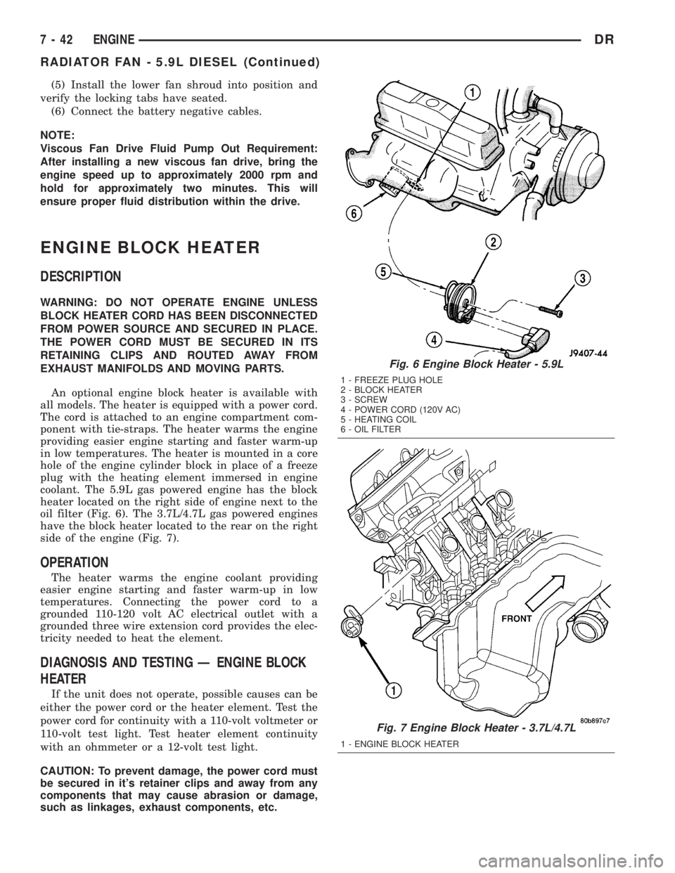
coolant. The 5.9L gas powered engine has the block
heater located on the right side of engine next to the
oil filter (Fig. 6). The 3.7L/4.7L gas powered engines
have the block heater located to the rear on the right
side of the engine (Fig. 7).
OPERATION
The heater warms the engine coolant providing
easier engine starting and faster warm-up in low
temperatures. Connecting the power cord to a
grounded 110-120 volt AC electrical outlet with a
grounded three wire extension cord provides the elec-
tricity needed to heat the element.
DIAGNOSIS AND TESTING Ð ENGINE BLOCK
HEATER
If the unit does not operate, possible causes can be
either the power cord or the heater element. Test the
power cord for continuity with a 110-volt voltmeter or
110-volt test light. Test heater element continuity
with an ohmmeter or a 12-volt test light.
CAUTION: To prevent damage, the power cord must
be secured in it's retainer clips and away from any
components that may cause abrasion or damage,
such as linkages, exhaust components, etc.
Fig. 6 Engine Block Heater - 5.9L
1 - FREEZE PLUG HOLE
2 - BLOCK HEATER
3 - SCREW
4 - POWER CORD (120V AC)
5 - HEATING COIL
6 - OIL FILTER
Fig. 7 Engine Block Heater - 3.7L/4.7L
1 - ENGINE BLOCK HEATER
7 - 42 ENGINEDR
RADIATOR FAN - 5.9L DIESEL (Continued)
Page 330 of 2895
REMOVAL
(1) Disconnect the battery negative cable.
(2) Drain the coolant (Refer to 7 - COOLING -
STANDARD PROCEDURE).
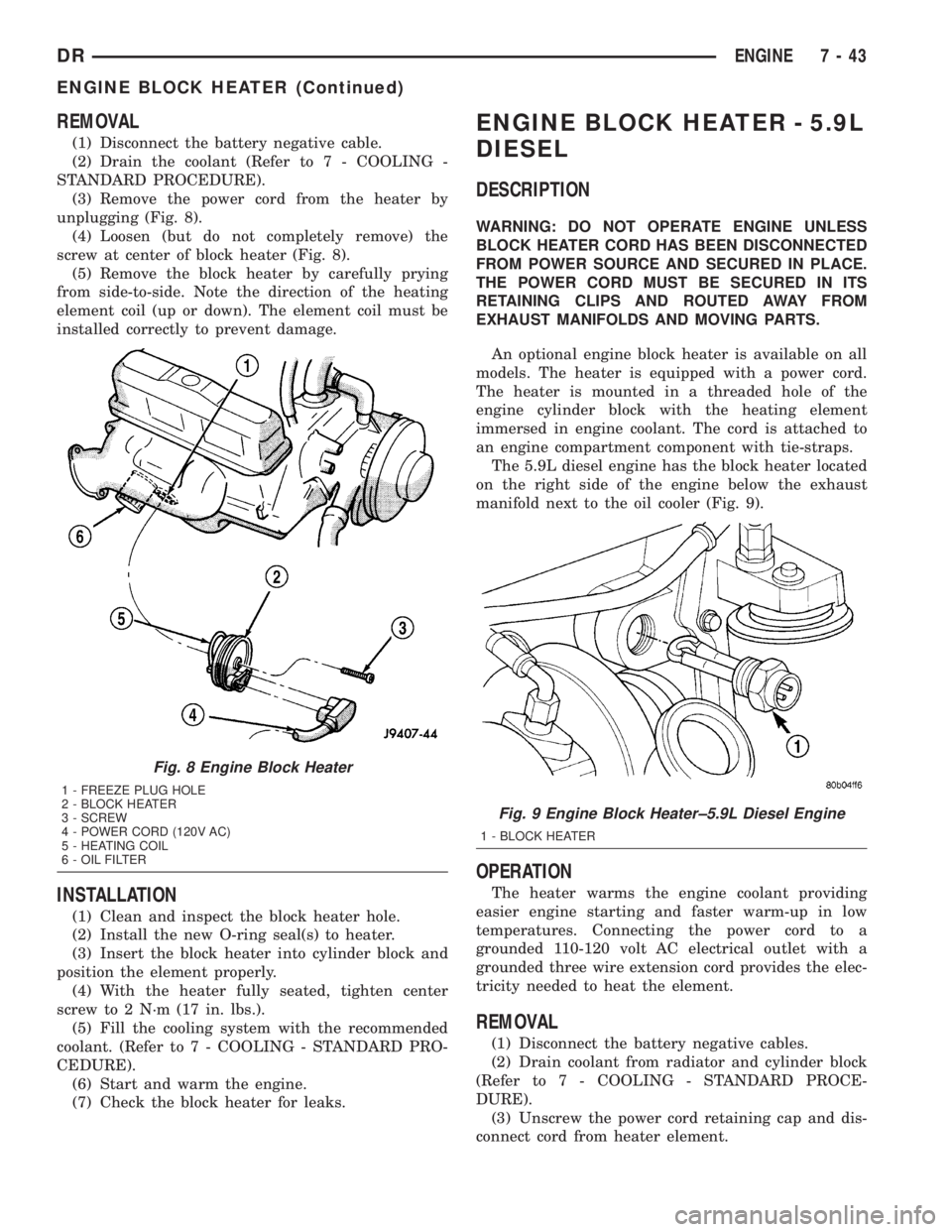
(3) Remove the power cord from the heater by
unplugging (Fig. 8).
(4) Loosen (but do not completely remove) the
screw at center of block heater (Fig. 8).
(5) Remove the block heater by carefully prying
from side-to-side. Note the direction of the heating
element coil (up or down). The element coil must be
installed correctly to prevent damage.
INSTALLATION
(1) Clean and inspect the block heater hole.
(2) Install the new O-ring seal(s) to heater.
(3) Insert the block heater into cylinder block and
position the element properly.
(4) With the heater fully seated, tighten center
screw to 2 N´m (17 in. lbs.).
(5) Fill the cooling system with the recommended
coolant. (Refer to 7 - COOLING - STANDARD PRO-
CEDURE).
(6) Start and warm the engine.
(7) Check the block heater for leaks.
ENGINE BLOCK HEATER - 5.9L
DIESEL
DESCRIPTION
WARNING: DO NOT OPERATE ENGINE UNLESS
BLOCK HEATER CORD HAS BEEN DISCONNECTED
FROM POWER SOURCE AND SECURED IN PLACE.
THE POWER CORD MUST BE SECURED IN ITS
RETAINING CLIPS AND ROUTED AWAY FROM
EXHAUST MANIFOLDS AND MOVING PARTS.
An optional engine block heater is available on all
models. The heater is equipped with a power cord.
The heater is mounted in a threaded hole of the
engine cylinder block with the heating element
immersed in engine coolant. The cord is attached to
an engine compartment component with tie-straps.
The 5.9L diesel engine has the block heater located
on the right side of the engine below the exhaust
manifold next to the oil cooler (Fig. 9).
OPERATION
The heater warms the engine coolant providing
easier engine starting and faster warm-up in low
temperatures. Connecting the power cord to a
grounded 110-120 volt AC electrical outlet with a
grounded three wire extension cord provides the elec-
tricity needed to heat the element.
REMOVAL
(1) Disconnect the battery negative cables.
(2) Drain coolant from radiator and cylinder block
(Refer to 7 - COOLING - STANDARD PROCE-
DURE).
(3) Unscrew the power cord retaining cap and dis-
connect cord from heater element.
Fig. 8 Engine Block Heater
1 - FREEZE PLUG HOLE
2 - BLOCK HEATER
3 - SCREW
4 - POWER CORD (120V AC)
5 - HEATING COIL
6 - OIL FILTER
Fig. 9 Engine Block Heater±5.9L Diesel Engine
1 - BLOCK HEATER
DRENGINE 7 - 43
ENGINE BLOCK HEATER (Continued)
Page 341 of 2895
(7) Start the engine and check for coolant leaks.
Run engine to check for proper thermostat operation.
FAN DRIVE VISCOUS CLUTCH
DESCRIPTION
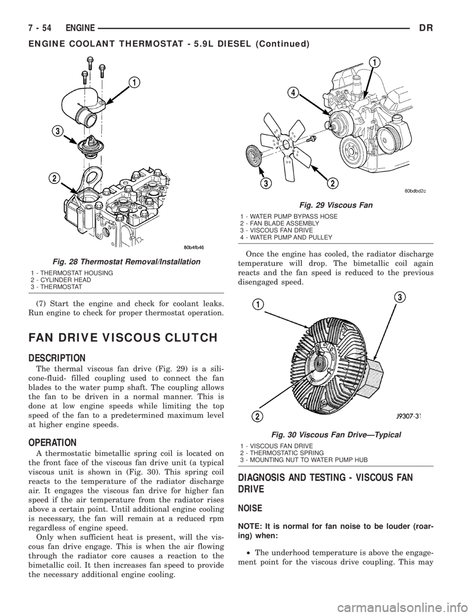
The thermal viscous fan drive (Fig. 29) is a sili-
cone-fluid- filled coupling used to connect the fan
blades to the water pump shaft. The coupling allows
the fan to be driven in a normal manner. This is
done at low engine speeds while limiting the top
speed of the fan to a predetermined maximum level
at higher engine speeds.
OPERATION
A thermostatic bimetallic spring coil is located on
the front face of the viscous fan drive unit (a typical
viscous unit is shown in (Fig. 30). This spring coil
reacts to the temperature of the radiator discharge
air. It engages the viscous fan drive for higher fan
speed if the air temperature from the radiator rises
above a certain point. Until additional engine cooling
is necessary, the fan will remain at a reduced rpm
regardless of engine speed.
Only when sufficient heat is present, will the vis-
cous fan drive engage. This is when the air flowing
through the radiator core causes a reaction to the
bimetallic coil. It then increases fan speed to provide
the necessary additional engine cooling.Once the engine has cooled, the radiator discharge
temperature will drop. The bimetallic coil again
reacts and the fan speed is reduced to the previous
disengaged speed.
DIAGNOSIS AND TESTING - VISCOUS FAN
DRIVE
NOISE
NOTE: It is normal for fan noise to be louder (roar-
ing) when:
²The underhood temperature is above the engage-
ment point for the viscous drive coupling. This may
Fig. 28 Thermostat Removal/Installation
1 - THERMOSTAT HOUSING
2 - CYLINDER HEAD
3 - THERMOSTAT
Fig. 29 Viscous Fan
1 - WATER PUMP BYPASS HOSE
2 - FAN BLADE ASSEMBLY
3 - VISCOUS FAN DRIVE
4 - WATER PUMP AND PULLEY
Fig. 30 Viscous Fan DriveÐTypical
1 - VISCOUS FAN DRIVE
2 - THERMOSTATIC SPRING
3 - MOUNTING NUT TO WATER PUMP HUB
7 - 54 ENGINEDR
ENGINE COOLANT THERMOSTAT - 5.9L DIESEL (Continued)
Page 342 of 2895
occur when ambient (outside air temperature) is very
high.
²Engine loads and temperatures are high such as
when towing a trailer.
²Cool silicone fluid within the fan drive unit is
being redistributed back to its normal disengaged
(warm) position. This can occur during the first 15
seconds to one minute after engine start-up on a cold
engine.
LEAKS
Viscous fan drive operation is not affected by small
oil stains near the drive bearing. If leakage appears
excessive, replace the fan drive unit.
VISCOUS DRIVE
If the fan assembly free-wheels without drag (the
fan blades will revolve more than five turns when
spun by hand), replace the fan drive. This spin test
must be performed when the engine is cool.
For the following test, the cooling system must be
in good condition. It also will ensure against exces-
sively high coolant temperature.
WARNING: BE SURE THAT THERE IS ADEQUATE
FAN BLADE CLEARANCE BEFORE DRILLING.
(1) Drill a 3.18-mm (1/8-in) diameter hole in the
top center of the fan shroud.
(2) Obtain a dial thermometer with an 8 inch stem
(or equivalent). It should have a range of -18É-to-
105ÉC (0É-to-220É F). Insert thermometer through the
hole in the shroud. Be sure that there is adequate
clearance from the fan blades.
(3) Connect a tachometer and an engine ignition
timing light. The timing light is to be used as a
strobe light. This step cannot be used on the diesel
engine.
(4) Block the air flow through the radiator. Secure
a sheet of plastic in front of the radiator. Use tape at
the top to secure the plastic and be sure that the air
flow is blocked.
(5) Be sure that the air conditioner (if equipped) is
turned off.
WARNING: USE EXTREME CAUTION WHEN THE
ENGINE IS OPERATING. DO NOT STAND IN A
DIRECT LINE WITH THE FAN. DO NOT PUT YOUR
HANDS NEAR THE PULLEYS, BELTS OR FAN. DO
NOT WEAR LOOSE CLOTHING.
(6) Start the engine and operate at 2400 rpm.
Within ten minutes the air temperature (indicated on
the dial thermometer) should be up to 88É C (190É F).
Fan driveengagementshould start to occur at/be-
tween:
²3.7L Automatic Ð 93É C - 99ÉC (200É F - 210É F)²3.7L Manual/4.7L Automatic/5.9L Ð 85É to 91É C
(185É to 195É F)
²4.7L Manual Ð 74É to 79É C (165É to 175É F)
²Engagement is distinguishable by a definite
increasein fan flow noise (roaring). The timing light
also will indicate an increase in the speed of the fan.
(7) When viscous drive engagement is verified,
remove the plastic sheet. Fan drivedisengagement
should start to occur at or between:
²3.7L Automatic Ð 76ÉC to 81ÉC (168É F to 178É
F)
²3.7L Manual/4.7L Auto/ 5.9L Ð 67ÉC to 73ÉC
(153É F to 163É F)
²4.7L Manual Ð 56ÉC to 62ÉC (133É F to 143É F)
²8.0L engine Ð 88É to 96É C (190É to 205É F) A
definitedecreaseof fan flow noise (roaring) should
be noticed. If not, replace the defective viscous fan
drive unit.
CAUTION: Some engines equipped with serpentine
drive belts have reverse rotating fans and viscous
fan drives. They are marked with the word
REVERSE to designate their usage. Installation of
the wrong fan or viscous fan drive can result in
engine overheating.
CAUTION: If the viscous fan drive is replaced
because of mechanical damage, the cooling fan
blades should also be inspected. Inspect for fatigue
cracks, loose blades, or loose rivets that could
have resulted from excessive vibration. Replace fan
blade assembly if any of these conditions are
found. Also inspect water pump bearing and shaft
assembly for any related damage due to a viscous
fan drive malfunction.
FAN DRIVE VISCOUS CLUTCH
- 5.9L DIESEL
DESCRIPTION
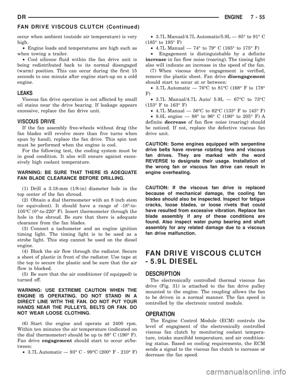
The electronically controlled thermal viscous fan
drive (Fig. 31) is attached to the fan drive pulley
mounted to the engine. The coupling allows the fan
to be driven in a normal manner. The fan speed is
controlled by the electronic control module.
OPERATION
The Engine Control Module (ECM) controls the
level of engagment of the electronically controlled
viscous fan clutch by monitoring coolant tempera-
ture, intake manifold temperature, and air condition-
ing status. Based on cooling requirements, the ECM
sends a signal to the viscous fan clutch to increase or
decrease the fan speed.
DRENGINE 7 - 55
FAN DRIVE VISCOUS CLUTCH (Continued)
Page 343 of 2895
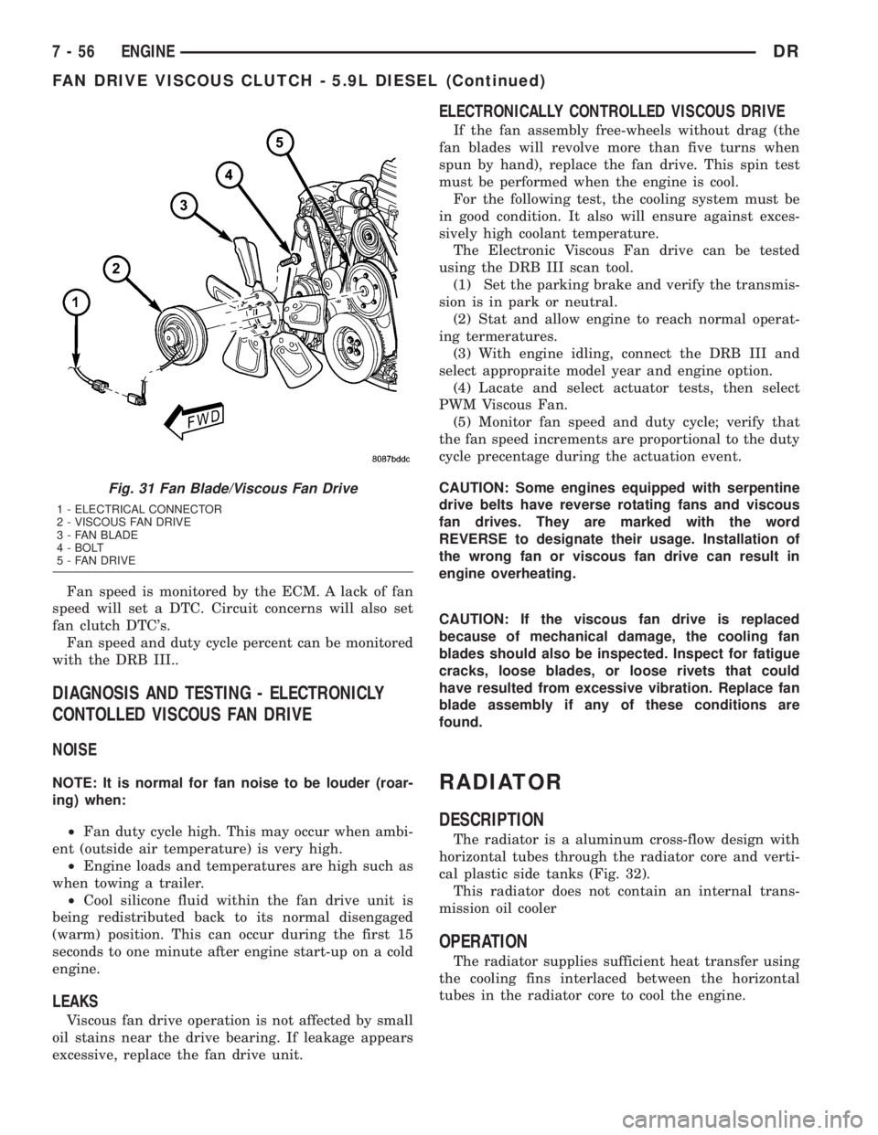
Fan speed is monitored by the ECM. A lack of fan
speed will set a DTC. Circuit concerns will also set
fan clutch DTC's.
Fan speed and duty cycle percent can be monitored
with the DRB III..
DIAGNOSIS AND TESTING - ELECTRONICLY
CONTOLLED VISCOUS FAN DRIVE
NOISE
NOTE: It is normal for fan noise to be louder (roar-
ing) when:
²Fan duty cycle high. This may occur when ambi-
ent (outside air temperature) is very high.
²Engine loads and temperatures are high such as
when towing a trailer.
²Cool silicone fluid within the fan drive unit is
being redistributed back to its normal disengaged
(warm) position. This can occur during the first 15
seconds to one minute after engine start-up on a cold
engine.
LEAKS
Viscous fan drive operation is not affected by small
oil stains near the drive bearing. If leakage appears
excessive, replace the fan drive unit.
ELECTRONICALLY CONTROLLED VISCOUS DRIVE
If the fan assembly free-wheels without drag (the
fan blades will revolve more than five turns when
spun by hand), replace the fan drive. This spin test
must be performed when the engine is cool.
For the following test, the cooling system must be
in good condition. It also will ensure against exces-
sively high coolant temperature.
The Electronic Viscous Fan drive can be tested
using the DRB III scan tool.
(1) Set the parking brake and verify the transmis-
sion is in park or neutral.
(2) Stat and allow engine to reach normal operat-
ing termeratures.
(3) With engine idling, connect the DRB III and
select appropraite model year and engine option.
(4) Lacate and select actuator tests, then select
PWM Viscous Fan.
(5) Monitor fan speed and duty cycle; verify that
the fan speed increments are proportional to the duty
cycle precentage during the actuation event.
CAUTION: Some engines equipped with serpentine
drive belts have reverse rotating fans and viscous
fan drives. They are marked with the word
REVERSE to designate their usage. Installation of
the wrong fan or viscous fan drive can result in
engine overheating.
CAUTION: If the viscous fan drive is replaced
because of mechanical damage, the cooling fan
blades should also be inspected. Inspect for fatigue
cracks, loose blades, or loose rivets that could
have resulted from excessive vibration. Replace fan
blade assembly if any of these conditions are
found.
RADIATOR
DESCRIPTION
The radiator is a aluminum cross-flow design with
horizontal tubes through the radiator core and verti-
cal plastic side tanks (Fig. 32).
This radiator does not contain an internal trans-
mission oil cooler
OPERATION
The radiator supplies sufficient heat transfer using
the cooling fins interlaced between the horizontal
tubes in the radiator core to cool the engine.
Fig. 31 Fan Blade/Viscous Fan Drive
1 - ELECTRICAL CONNECTOR
2 - VISCOUS FAN DRIVE
3 - FAN BLADE
4 - BOLT
5 - FAN DRIVE
7 - 56 ENGINEDR
FAN DRIVE VISCOUS CLUTCH - 5.9L DIESEL (Continued)
Page 344 of 2895

DIAGNOSIS AND TESTINGÐRADIATOR
COOLANT FLOW
Use the following procedure to determine if coolant
is flowing through the cooling system.
(1) Idle engine until operating temperature is
reached. If the upper radiator hose is warm to the
touch, the thermostat is opening and coolant is flow-
ing to the radiator.
WARNING: HOT, PRESSURIZED COOLANT CAN
CAUSE INJURY BY SCALDING. USING A RAG TO
COVER THE RADIATOR PRESSURE CAP, OPEN
RADIATOR CAP SLOWLY TO THE FIRST STOP. THIS
WILL ALLOW ANY BUILT-UP PRESSURE TO VENT
TO THE RESERVE/OVERFLOW TANK. AFTER PRES-
SURE BUILD-UP HAS BEEN RELEASED, REMOVE
CAP FROM FILLER NECK.
(2) Drain a small amount of coolant from the radi-
ator until the ends of the radiator tubes are visible
through the filler neck. Idle the engine at normal
operating temperature. If coolant is flowing past the
exposed tubes, the coolant is circulating.
REMOVAL
(1) Disconnect battery negative cables.WARNING: DO NOT REMOVE THE CYLINDER
BLOCK DRAIN PLUGS OR LOOSEN THE RADIATOR
DRAINCOCK WITH THE SYSTEM HOT AND UNDER
PRESSURE. SERIOUS BURNS FROM THE COOL-
ANT CAN OCCUR.
(2) Drain the cooling system (Refer to 7 - COOL-
ING - STANDARD PROCEDURE).
WARNING: CONSTANT TENSION HOSE CLAMPS
ARE USED ON MOST COOLING SYSTEM HOSES.
WHEN REMOVING OR INSTALLING, USE ONLY
TOOLS DESIGNED FOR SERVICING THIS TYPE OF
CLAMP. ALWAYS WEAR SAFETY GLASSES WHEN
SERVICING CONSTANT TENSION CLAMPS.
CAUTION: A number or letter is stamped into the
tongue of constant tension clamps. If replacement
is necessary, use only an original equipment clamp
with a matching number or letter and the correct
width.
(3) Remove the hose clamps and hoses from radia-
tor.
(4) Remove the coolant reserve/overflow tank hose
from the radiator filler neck.
(5) Remove the coolant reserve/overflow tank
(5.9L) or the coolant degas container(3.7L/4.7L) from
the fan shroud (pull straight up). The tank slips into
slots on the fan shroud.
(6) Unclip the power steering hoses from the fan
shroud.
(7) Disconnect the electrical connectors at the
windshield washer reservoir tank and remove the
tank.
(8) Remove the fan shroud mounting bolts and pull
up and out of the radiator tank clips (Fig. 33). Posi-
tion shroud rearward over the fan blades towards
engine.
(9) Disconnect the transmission cooler lines from
the transmission cooler, then plug the transmission
lines and cooler to prevent leakage.
(10) Disconnect the power steering lines from the
power steering cooler, then plug the power steering
lines and cooler to prevent leakage.
(11) Remove the two radiator upper mounting
bolts (Fig. 34).
(12) Lift the radiator straight up and out of the
engine compartment. Take care not to damage cool-
ing fins or tubes on the radiator and oil coolers when
removing.
Fig. 32 Radiator Ð Typical
1 - SCREW
2 - SCREW
3 - LOWER MOUNT
4 - RADIATOR
5 - DRAINCOCK
6 -LOWER MOUNT
DRENGINE 7 - 57
RADIATOR (Continued)
Page 345 of 2895
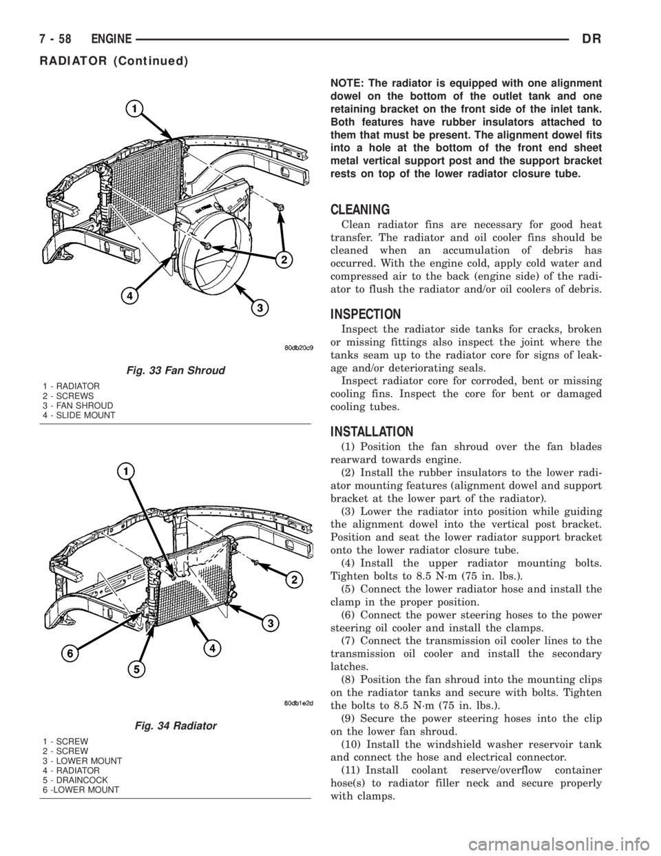
NOTE: The radiator is equipped with one alignment
dowel on the bottom of the outlet tank and one
retaining bracket on the front side of the inlet tank.
Both features have rubber insulators attached to
them that must be present. The alignment dowel fits
into a hole at the bottom of the front end sheet
metal vertical support post and the support bracket
rests on top of the lower radiator closure tube.
CLEANING
Clean radiator fins are necessary for good heat
transfer. The radiator and oil cooler fins should be
cleaned when an accumulation of debris has
occurred. With the engine cold, apply cold water and
compressed air to the back (engine side) of the radi-
ator to flush the radiator and/or oil coolers of debris.
INSPECTION
Inspect the radiator side tanks for cracks, broken
or missing fittings also inspect the joint where the
tanks seam up to the radiator core for signs of leak-
age and/or deteriorating seals.
Inspect radiator core for corroded, bent or missing
cooling fins. Inspect the core for bent or damaged
cooling tubes.
INSTALLATION
(1) Position the fan shroud over the fan blades
rearward towards engine.
(2) Install the rubber insulators to the lower radi-
ator mounting features (alignment dowel and support
bracket at the lower part of the radiator).
(3) Lower the radiator into position while guiding
the alignment dowel into the vertical post bracket.
Position and seat the lower radiator support bracket
onto the lower radiator closure tube.
(4) Install the upper radiator mounting bolts.
Tighten bolts to 8.5 N´m (75 in. lbs.).
(5) Connect the lower radiator hose and install the
clamp in the proper position.
(6) Connect the power steering hoses to the power
steering oil cooler and install the clamps.
(7) Connect the transmission oil cooler lines to the
transmission oil cooler and install the secondary
latches.
(8) Position the fan shroud into the mounting clips
on the radiator tanks and secure with bolts. Tighten
the bolts to 8.5 N´m (75 in. lbs.).
(9) Secure the power steering hoses into the clip
on the lower fan shroud.
(10) Install the windshield washer reservoir tank
and connect the hose and electrical connector.
(11) Install coolant reserve/overflow container
hose(s) to radiator filler neck and secure properly
with clamps.
Fig. 33 Fan Shroud
1 - RADIATOR
2 - SCREWS
3 - FAN SHROUD
4 - SLIDE MOUNT
Fig. 34 Radiator
1 - SCREW
2 - SCREW
3 - LOWER MOUNT
4 - RADIATOR
5 - DRAINCOCK
6 -LOWER MOUNT
7 - 58 ENGINEDR
RADIATOR (Continued)