2003 DODGE RAM ECO mode
[x] Cancel search: ECO modePage 587 of 2895

STANDARD PROCEDURE - RKE TRANSMITTER
PROGRAMING
New Remote Keyless Entry (RKE) transmitters can
be programed using the DRB IIItscan tool and the
proper Diagnostic Procedures manual. The DRB IIIt
scan tool can provide confirmation that the PCI data
bus is functional, and that all of the electronic mod-
ules are sending and receiving the proper messages
on the PCI data bus.
The following procedure can be used as long as one
programmed transmitter is available:
NOTE: When entering program mode using that
programmed fob, ALL currently programmed fobs
will be erased and they will have to be repro-
grammed for the vehicle. If program mode is
entered and no action is performed, the previously
programmed fobs will continue to function.
(1) Enter the vehicle and close all doors.
(2) Fasten the seat belt (this will cancel the seat
belt chime). Turn the ignition to the RUN position.
(3) Press and hold the UNLOCK button on a pro-
grammed transmitter for 4 to 10 seconds. Within the
4 to 10 seconds with the UNLOCK button still
depressed, press the PANIC button for one second.
When a single chime is heard, release both button-
s.The chime indicates the system is in program
mode.(4) Press and release both the LOCK and
UNLOCK buttons simultaneously on a fob to be pro-
grammed. A single chime will be heard, this indicates
the fob has been recognized.
(5) Press and release any button on the same fob.
A single chime will be heard, this indicates the fob
has been programmed.
(6) Repeat steps 4 and 5 for up to a total of 4 fobs.
(7) Turn the ignition OFF.
(8) Turn the ignition ON or wait 60 seconds.
The vehicle will remain in program mode for up to
60 seconds from when the original chime (step 3) was
heard. After 60 seconds, all programmed transmitters
will function normally.
SPECIFICATIONS - REMOTE KEYLESS ENTRY
TRANSMITTER
RANGE
Normal operation range is up to a distance of 3 to
7 meters (10 to 23 ft.) of the vehicle. Range may be
better or worse depending on the environment
around the vehicle.
8N - 10 POWER LOCKSDR
REMOTE KEYLESS ENTRY TRANSMITTER (Continued)
Page 604 of 2895
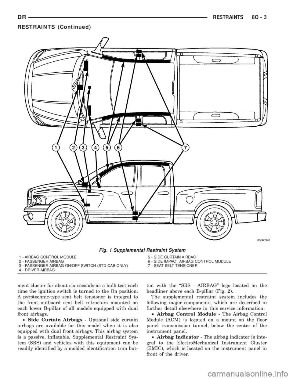
ment cluster for about six seconds as a bulb test each
time the ignition switch is turned to the On position.
A pyrotechnic-type seat belt tensioner is integral to
the front outboard seat belt retractors mounted on
each lower B-pillar of all models equipped with dual
front airbags.
²Side Curtain Airbags- Optional side curtain
airbags are available for this model when it is also
equipped with dual front airbags. This airbag system
is a passive, inflatable, Supplemental Restraint Sys-
tem (SRS) and vehicles with this equipment can be
readily identified by a molded identification trim but-ton with the ªSRS - AIRBAGº logo located on the
headliner above each B-pillar (Fig. 2).
The supplemental restraint system includes the
following major components, which are described in
further detail elsewhere in this service information:
²Airbag Control Module- The Airbag Control
Module (ACM) is located on a mount on the floor
panel transmission tunnel, below the center of the
instrument panel.
²Airbag Indicator- The airbag indicator is inte-
gral to the ElectroMechanical Instrument Cluster
(EMIC), which is located on the instrument panel in
front of the driver.
Fig. 1 Supplemental Restraint System
1 - AIRBAG CONTROL MODULE
2 - PASSENGER AIRBAG
3 - PASSENGER AIRBAG ON/OFF SWITCH (STD CAB ONLY)
4 - DRIVER AIRBAG5 - SIDE CURTAIN AIRBAG
6 - SIDE IMPACT AIRBAG CONTROL MODULE
7 - SEAT BELT TENSIONER
DRRESTRAINTS 8O - 3
RESTRAINTS (Continued)
Page 610 of 2895
If the stored DTC information is successfully erased,
go to Step 9.
(9) Turn the ignition switch to the Off position for
about fifteen seconds, and then back to the On posi-
tion. Observe the airbag indicator in the instrument
cluster. It should illuminate for six to eight seconds,
and then go out. This indicates that the supplemen-
tal restraint system is functioning normally and that
the repairs are complete. If the airbag indicator fails
to light, or lights and stays on, there is still an active
supplemental restraint system fault or malfunction.
Refer to the appropriate diagnostic information to
diagnose the problem.
ACM COVER
REMOVAL
The Airbag Control Module (ACM) cover is used
only on models with an automatic transmission. Mod-
els with a manual transmission require that the floor
console be removed to access the ACM for service.
(Refer to 23 - BODY/INTERIOR/FLOOR CONSOLE -
REMOVAL).
WARNING: ON VEHICLES EQUIPPED WITH AIR-
BAGS, DISABLE THE SUPPLEMENTAL RESTRAINT
SYSTEM BEFORE ATTEMPTING ANY STEERING
WHEEL, STEERING COLUMN, DRIVER AIRBAG,
PASSENGER AIRBAG, SEAT BELT TENSIONER,
SIDE CURTAIN AIRBAG, OR INSTRUMENT PANEL
COMPONENT DIAGNOSIS OR SERVICE. DISCON-
NECT AND ISOLATE THE BATTERY NEGATIVE
(GROUND) CABLE, THEN WAIT TWO MINUTES FOR
THE SYSTEM CAPACITOR TO DISCHARGE BEFORE
PERFORMING FURTHER DIAGNOSIS OR SERVICE.
THIS IS THE ONLY SURE WAY TO DISABLE THE
SUPPLEMENTAL RESTRAINT SYSTEM. FAILURE TO
TAKE THE PROPER PRECAUTIONS COULD
RESULT IN ACCIDENTAL AIRBAG DEPLOYMENT
AND POSSIBLE PERSONAL INJURY.
(1) Disconnect and isolate the battery negative
cable. Wait two minutes for the system capacitor to
discharge before further service.
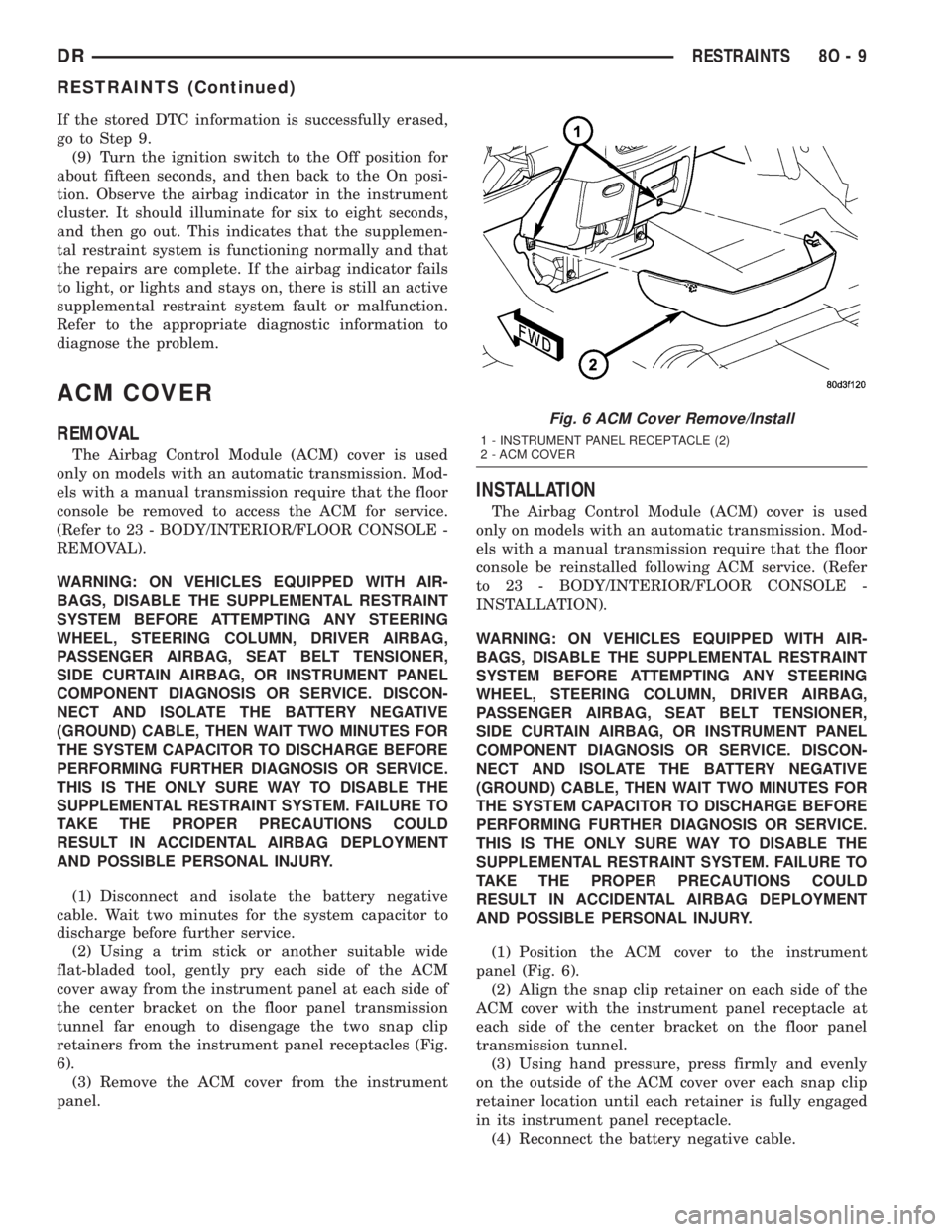
(2) Using a trim stick or another suitable wide
flat-bladed tool, gently pry each side of the ACM
cover away from the instrument panel at each side of
the center bracket on the floor panel transmission
tunnel far enough to disengage the two snap clip
retainers from the instrument panel receptacles (Fig.
6).
(3) Remove the ACM cover from the instrument
panel.
INSTALLATION
The Airbag Control Module (ACM) cover is used
only on models with an automatic transmission. Mod-
els with a manual transmission require that the floor
console be reinstalled following ACM service. (Refer
to 23 - BODY/INTERIOR/FLOOR CONSOLE -
INSTALLATION).
WARNING: ON VEHICLES EQUIPPED WITH AIR-
BAGS, DISABLE THE SUPPLEMENTAL RESTRAINT
SYSTEM BEFORE ATTEMPTING ANY STEERING
WHEEL, STEERING COLUMN, DRIVER AIRBAG,
PASSENGER AIRBAG, SEAT BELT TENSIONER,
SIDE CURTAIN AIRBAG, OR INSTRUMENT PANEL
COMPONENT DIAGNOSIS OR SERVICE. DISCON-
NECT AND ISOLATE THE BATTERY NEGATIVE
(GROUND) CABLE, THEN WAIT TWO MINUTES FOR
THE SYSTEM CAPACITOR TO DISCHARGE BEFORE
PERFORMING FURTHER DIAGNOSIS OR SERVICE.
THIS IS THE ONLY SURE WAY TO DISABLE THE
SUPPLEMENTAL RESTRAINT SYSTEM. FAILURE TO
TAKE THE PROPER PRECAUTIONS COULD
RESULT IN ACCIDENTAL AIRBAG DEPLOYMENT
AND POSSIBLE PERSONAL INJURY.
(1) Position the ACM cover to the instrument
panel (Fig. 6).
(2) Align the snap clip retainer on each side of the
ACM cover with the instrument panel receptacle at
each side of the center bracket on the floor panel
transmission tunnel.
(3) Using hand pressure, press firmly and evenly
on the outside of the ACM cover over each snap clip
retainer location until each retainer is fully engaged
in its instrument panel receptacle.
(4) Reconnect the battery negative cable.
Fig. 6 ACM Cover Remove/Install
1 - INSTRUMENT PANEL RECEPTACLE (2)
2 - ACM COVER
DRRESTRAINTS 8O - 9
RESTRAINTS (Continued)
Page 612 of 2895

On models equipped with optional side curtain air-
bags, the ACM communicates with both the left and
right Side Impact Airbag Control Modules (SIACM)
over the PCI data bus. The SIACM notifies the ACM
when it has detected a monitored system fault and
stored a DTC in memory for its respective side cur-
tain airbag system, and the ACM sets a DTC and
controls the airbag indicator operation accordingly.
The ACM receives battery current through two cir-
cuits; a fused ignition switch output (run) circuit
through a fuse in the Integrated Power Module
(IPM), and a fused ignition switch output (run-start)
circuit through a second fuse in the IPM. The ACM
receives ground through a ground circuit and take
out of the instrument panel wire harness. This take
out has a single eyelet terminal connector that is
secured by a ground screw to the instrument panel
support structure. These connections allow the ACM
to be operational whenever the ignition switch is in
the Start or On positions. The ACM also contains an
energy-storage capacitor. When the ignition switch is
in the Start or On positions, this capacitor is contin-
ually being charged with enough electrical energy to
deploy the front supplemental restraint components
for up to one second following a battery disconnect or
failure. The purpose of the capacitor is to provide
backup supplemental restraint system protection in
case there is a loss of battery current supply to the
ACM during an impact.
Two sensors are contained within the ACM; an
electronic impact sensor, and a safing sensor. The
electronic impact sensor is an accelerometer that
senses the rate of vehicle deceleration, which pro-
vides verification of the direction and severity of an
impact. The safing sensor is an electromechanical
sensor within the ACM that provides an additional
logic input to the ACM microprocessor. The safing
sensor is a normally open switch that is used to ver-
ify the need for a front supplemental restraint
deployment by detecting impact energy of a lesser
magnitude than that of the electronic impact sensor,
and must be closed in order for the front airbags or
seat belt tensioners to deploy. A pre-programmed
decision algorithm in the ACM microprocessor deter-
mines when the deceleration rate as signaled by the
impact sensor and the safing sensor indicate an
impact that is severe enough to require front supple-
mental restraint system protection and, based upon
the status of the passenger airbag on/off switch input
and the severity of the monitored impact, determines
what combination of seat belt tensioner and front air-
bag deployment is required for each front seating
position. When the programmed conditions are met,
the ACM sends the proper electrical signals to deploy
the seat belt tensioners and dual front airbags.The hard wired inputs and outputs for the ACM
may be diagnosed and tested using conventional
diagnostic tools and procedures. However, conven-
tional diagnostic methods will not prove conclusive in
the diagnosis of the ACM, the PCI data bus network,
or the electronic message inputs to and outputs from
the ACM. The most reliable, efficient, and accurate
means to diagnose the ACM, the PCI data bus net-
work, and the electronic message inputs to and out-
puts from the ACM requires the use of a DRBIIIt
scan tool. Refer to the appropriate diagnostic infor-
mation.
REMOVAL
WARNING: ON VEHICLES EQUIPPED WITH AIR-
BAGS, DISABLE THE SUPPLEMENTAL RESTRAINT
SYSTEM BEFORE ATTEMPTING ANY STEERING
WHEEL, STEERING COLUMN, DRIVER AIRBAG,
PASSENGER AIRBAG, SEAT BELT TENSIONER,
SIDE CURTAIN AIRBAG, OR INSTRUMENT PANEL
COMPONENT DIAGNOSIS OR SERVICE. DISCON-
NECT AND ISOLATE THE BATTERY NEGATIVE
(GROUND) CABLE, THEN WAIT TWO MINUTES FOR
THE SYSTEM CAPACITOR TO DISCHARGE BEFORE
PERFORMING FURTHER DIAGNOSIS OR SERVICE.
THIS IS THE ONLY SURE WAY TO DISABLE THE
SUPPLEMENTAL RESTRAINT SYSTEM. FAILURE TO
TAKE THE PROPER PRECAUTIONS COULD
RESULT IN ACCIDENTAL AIRBAG DEPLOYMENT
AND POSSIBLE PERSONAL INJURY.
WARNING: THE AIRBAG CONTROL MODULE CON-
TAINS THE IMPACT SENSOR, WHICH ENABLES
THE SYSTEM TO DEPLOY THE FRONT SUPPLE-
MENTAL RESTRAINTS. NEVER STRIKE OR DROP
THE AIRBAG CONTROL MODULE, AS IT CAN DAM-
AGE THE IMPACT SENSOR OR AFFECT ITS CALI-
BRATION. IF AN AIRBAG CONTROL MODULE IS
ACCIDENTALLY DROPPED DURING SERVICE, THE
MODULE MUST BE SCRAPPED AND REPLACED
WITH A NEW UNIT. FAILURE TO OBSERVE THIS
WARNING COULD RESULT IN ACCIDENTAL,
INCOMPLETE, OR IMPROPER FRONT SUPPLEMEN-
TAL RESTRAINT DEPLOYMENT AND POSSIBLE
OCCUPANT INJURIES.
(1) Disconnect and isolate the battery negative
cable. Wait two minutes for the system capacitor to
discharge before further service.
(2) On models with a manual transmission,
remove the floor console from the top of the floor
panel transmission tunnel. (Refer to 23 - BODY/IN-
TERIOR/FLOOR CONSOLE - REMOVAL).
(3) On models with an automatic transmission,
remove the ACM cover from the instrument panel.
DRRESTRAINTS 8O - 11
AIRBAG CONTROL MODULE (Continued)
Page 614 of 2895
the locating pins on the bottom of the ACM mounting
flanges into the locating holes in the bracket.
(3) Still working from the left side of the floor
panel transmission tunnel, install and tighten the
two screws that secure the left ACM mounting
flanges to the bracket that is welded onto the floor
panel transmission tunnel. Tighten the screws to 14
N´m (10 ft. lbs.).
(4) From the right side of the floor panel transmis-
sion tunnel, tighten each of the two screws that
secure the right side of the ACM to the bracket on
the floor panel transmission tunnel. Tighten the
screws to 14 N´m (10 ft. lbs.).
(5) Reach through the rearward facing opening
below the instrument panel center stack support
bracket on the top of the floor panel transmission
tunnel to access and reconnect the instrument panel
wire harness connector for the ACM to the ACM con-
nector receptacle located on the rearward facing side
of the module. Be certain that the latch and the red
Connector Position Assurance (CPA) lock on the con-
nector are each fully engaged.
(6) On models with an automatic transmission,
reinstall the ACM cover onto the instrument panel.
(Refer to 8 - ELECTRICAL/RESTRAINTS/ACM
COVER - INSTALLATION).
(7) On models with a manual transmission, rein-
stall the floor console onto the top of the floor panel
transmission tunnel. (Refer to 23 - BODY/INTERI-
OR/FLOOR CONSOLE - INSTALLATION).
(8) Do not reconnect the battery negative cable at
this time. The supplemental restraint system verifi-
cation test procedure should be performed following
service of any supplemental restraint system compo-
nent. (Refer to 8 - ELECTRICAL/RESTRAINTS -
STANDARD PROCEDURE - VERIFICATION TEST).AUTOMATIC LOCKING
RETRACTOR
DESCRIPTION
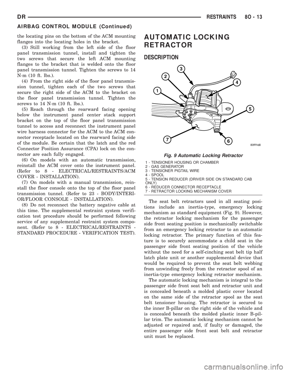
The seat belt retractors used in all seating posi-
tions include an inertia-type, emergency locking
mechanism as standard equipment (Fig. 9). However,
the retractor locking mechanism for the passenger
side front seating position is mechanically switchable
from an emergency locking retractor to an automatic
locking retractor. The primary function of this fea-
ture is to securely accommodate a child seat in the
passenger side front seating position of the vehicle
without the need for a self-cinching seat belt tip half
latch plate unit or another supplemental device that
would be required to prevent the seat belt webbing
from unwinding freely from the retractor spool of an
inertia-type emergency locking retractor mechanism.
The automatic locking mechanism is integral to the
passenger side front seat belt and retractor unit and
is concealed beneath a molded plastic cover located
on the same side of the retractor spool as the seat
belt tensioner housing. The retractor is secured to
the inner B-pillar on the right side of the vehicle and
is concealed beneath the molded plastic inner B-pil-
lar trim. The automatic locking mechanism cannot be
adjusted or repaired and, if faulty or damaged, the
entire passenger side front seat belt and retractor
unit must be replaced.
Fig. 9 Automatic Locking Retractor
1 - TENSIONER HOUSING OR CHAMBER
2 - GAS GENERATOR
3 - TENSIONER PIGTAIL WIRE
4 - SPOOL
5 - TENSION REDUCER (DRIVER SIDE ON STANDARD CAB
ONLY)
6 - REDUCER CONNECTOR RECEPTACLE
7 - RETRACTOR LOCKING MECHANISM COVER
DRRESTRAINTS 8O - 13
AIRBAG CONTROL MODULE (Continued)
Page 615 of 2895
OPERATION
The automatic locking mode of the retractor is
engaged and the retractor is switched from operating
as a standard inertia-type emergency locking retrac-
tor by first buckling the combination lap and shoul-
der belt buckle. Then grasp the shoulder belt and
pull all of the webbing out of the retractor. Once all
of the belt webbing is extracted from the spool, the
retractor will automatically become engaged in the
pre-locked automatic locking mode and will make an
audible clicking or ratcheting sound as the shoulder
belt is allowed to retract to confirm that the auto-
matic locking mode is now engaged. Once the auto-
matic locking mode is engaged, the retractor will
remain locked and the belt will remain tight around
whatever it is restraining.The retractor is returned to standard emergency
locking mode by unbuckling the combination lap and
shoulder belt buckle and allowing the belt webbing to
be almost fully retracted onto the retractor spool. The
emergency locking mode is confirmed by the absence
of the audible clicking or ratcheting sound as the belt
webbing retracts. This mode will allow the belt to
unwind from and wind onto the retractor spool freely
unless and until a predetermined inertia load is
sensed, or until the retractor is again switched to the
automatic locking mode.
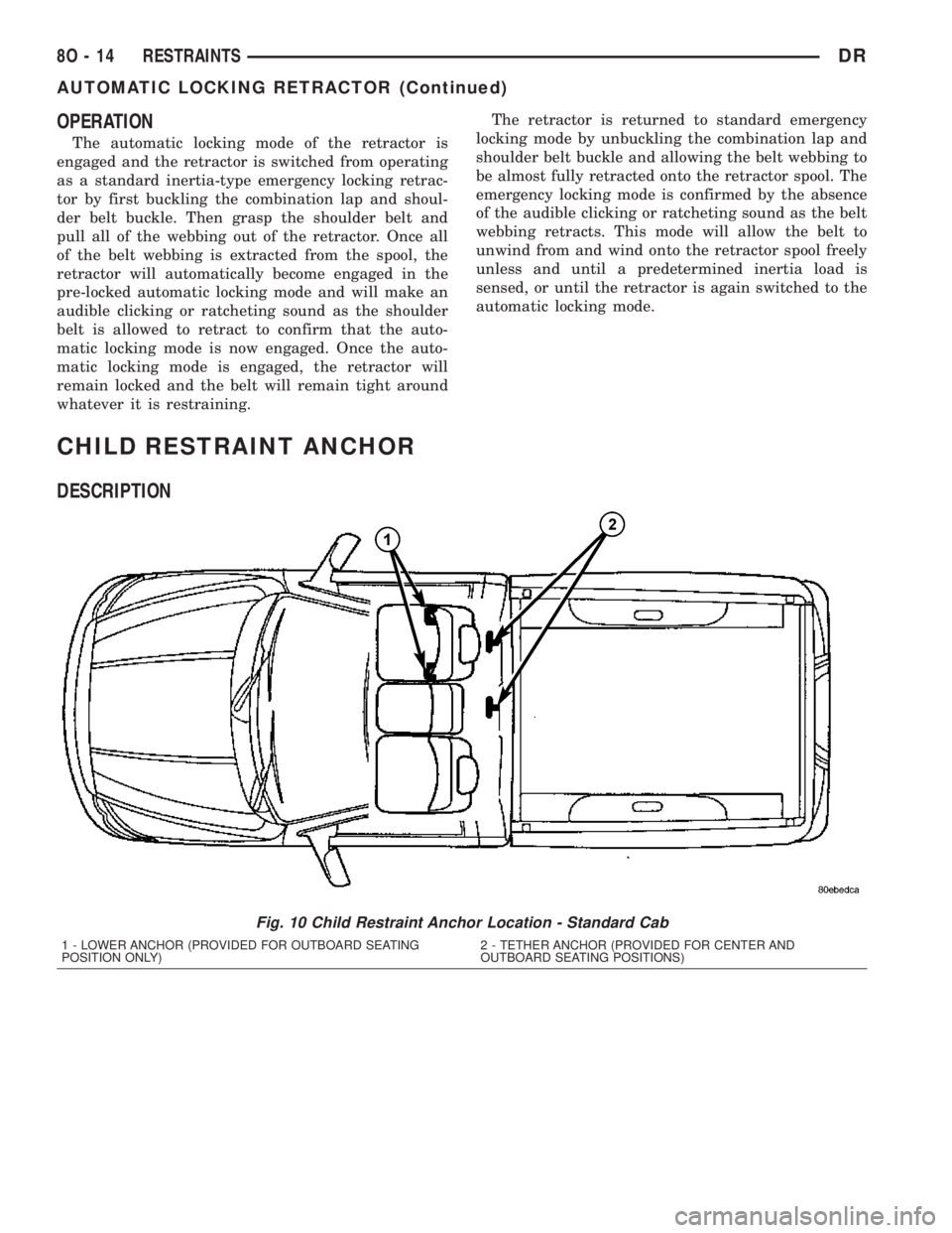
CHILD RESTRAINT ANCHOR
DESCRIPTION
Fig. 10 Child Restraint Anchor Location - Standard Cab
1 - LOWER ANCHOR (PROVIDED FOR OUTBOARD SEATING
POSITION ONLY)2 - TETHER ANCHOR (PROVIDED FOR CENTER AND
OUTBOARD SEATING POSITIONS)
8O - 14 RESTRAINTSDR
AUTOMATIC LOCKING RETRACTOR (Continued)
Page 623 of 2895
NOTE: When reinstalling the steering wheel, be cer-
tain to index the yellow rubber booted engagement
dowel on the upper surface of the clockspring rotor
between the two fins cast into the lower surface of
the steering wheel armature hub.
(12) Reinstall the steering wheel onto the steering
column. (Refer to 19 - STEERING/COLUMN/STEER-
ING WHEEL - INSTALLATION).
(13) Reconnect the steering wheel wire harness
connectors to the upper clockspring connector recep-
tacles. Be certain that the steering wheel wire har-
ness is routed between the steering wheel back trim
cover and the steering wheel armature.
(14) Reinstall the driver airbag onto the steering
wheel. (Refer to 8 - ELECTRICAL/RESTRAINTS/
DRIVER AIRBAG - INSTALLATION).
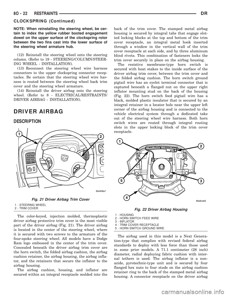
DRIVER AIRBAG
DESCRIPTION
The color-keyed, injection molded, thermoplastic
driver airbag protective trim cover is the most visible
part of the driver airbag (Fig. 21). The driver airbag
is located in the center of the steering wheel, where
it is secured with two screws to the armature of the
four-spoke steering wheel. All models have a Dodge
Ram logo embossed in the center of the trim cover.
Concealed beneath the driver airbag trim cover are
the horn switch, the folded airbag cushion, the airbag
cushion retainer, the airbag housing, the airbag infla-
tor, and the retainers that secure the inflator to the
airbag housing.
The airbag cushion, housing, and inflator are
secured within an integral receptacle molded into theback of the trim cover. The stamped metal airbag
housing is secured by integral tabs that engage slot-
ted locking blocks at the top and bottom of the trim
cover receptacle, an integral metal hook inserted
through a window in the vertical wall of the trim
cover receptacle at each side, and by three aluminum
blind rivets. This combination of fasteners locks the
trim cover securely in place on the airbag housing.
The resistive membrane-type horn switch is
secured with heat stakes to the inside surface of the
driver airbag trim cover, between the trim cover and
the folded airbag cushion. The horn switch ground
pigtail wire has an eyelet terminal connector that is
captured beneath a flanged nut on the upper right
inflator mounting stud on the back of the housing
(Fig. 22). The horn switch feed pigtail wire has a
black, molded plastic insulator that is secured by an
integral retainer in a locator hole near the upper left
corner of the airbag housing and is connected to the
vehicle electrical system through a dedicated take
out of the steering wheel wire harness. Both horn
switch wires are routed through integral routing
slots in the upper locking block of the trim cover
receptacle.
The airbag used in this model is a Next Genera-
tion-type that complies with revised federal airbag
standards to deploy with less force than those used
in some prior models. A 71.1 centimeter (28 inch)
diameter, radial deploying fabric cushion with inter-
nal tethers is used. The airbag inflator is a non-
azide, pyrotechnic-type unit and is secured by four
flanged hex nuts to four studs on the airbag cushion
retainer ring to the back of the stamped metal airbag
housing. A connector receptacle on the driver airbag
Fig. 21 Driver Airbag Trim Cover
1 - STEERING WHEEL
2 - TRIM COVER
Fig. 22 Driver Airbag Housing
1 - HOUSING
2 - HORN SWITCH FEED WIRE
3 - INFLATOR
4 - TRIM COVER RECEPTACLE
5 - HORN SWITCH GROUND WIRE
8O - 22 RESTRAINTSDR
CLOCKSPRING (Continued)
Page 626 of 2895
steering wheel hub area are not pinched between the
driver airbag and the steering wheel armature.
(5) Install and tighten the two screws that secure
the driver airbag to the steering wheel armature.
Tighten the screws to 14 N´m (120 in. lbs.).
(6) From the top of the steering wheel, position the
two trim covers or speed control switches into the
pockets on each side of the driver airbag trim cover.
(7) From the underside of the steering wheel,
install and tighten the two screws that secure the
two trim covers or speed control switches to each side
of the driver airbag trim cover. Tighten the screws to
2 N´m (15 in. lbs.).
(8) Do not reconnect the battery negative cable at
this time. The supplemental restraint system verifi-
cation test procedure should be performed following
service of any supplemental restraint system compo-
nent. (Refer to 8 - ELECTRICAL/RESTRAINTS -
STANDARD PROCEDURE - VERIFICATION TEST).
FRONT CENTER SEAT BELT &
RETRACTOR
REMOVAL
A front center seat belt and retractor is used only
on standard cab models. Quad cab models have a lap
belt in the front center seating position. (Refer to 8 -
ELECTRICAL/RESTRAINTS/FRONT CENTER
SEAT BELT BUCKLE - REMOVAL).
WARNING: DURING AND FOLLOWING ANY SEAT
BELT OR CHILD RESTRAINT ANCHOR SERVICE,
CAREFULLY INSPECT ALL SEAT BELTS, BUCKLES,
MOUNTING HARDWARE, RETRACTORS, TETHER
STRAPS, AND ANCHORS FOR PROPER INSTALLA-
TION, OPERATION, OR DAMAGE. REPLACE ANY
BELT THAT IS CUT, FRAYED, OR TORN.
STRAIGHTEN ANY BELT THAT IS TWISTED.
TIGHTEN ANY LOOSE FASTENERS. REPLACE ANY
BELT THAT HAS A DAMAGED OR INOPERATIVE
BUCKLE OR RETRACTOR. REPLACE ANY BELT
THAT HAS A BENT OR DAMAGED LATCH PLATE
OR ANCHOR PLATE. REPLACE ANY CHILD
RESTRAINT ANCHOR OR THE UNIT TO WHICH THE
ANCHOR IS INTEGRAL THAT HAS BEEN BENT OR
DAMAGED. NEVER ATTEMPT TO REPAIR A SEAT
BELT OR CHILD RESTRAINT COMPONENT.
ALWAYS REPLACE DAMAGED OR FAULTY SEAT
BELT AND CHILD RESTRAINT COMPONENTS WITH
THE CORRECT, NEW AND UNUSED REPLACEMENT
PARTS LISTED IN THE DAIMLERCHRYSLER MOPAR
PARTS CATALOG.
(1) Reach between the center of the front seat
cushion and front seat back to access and unbucklethe front center seat belt lower anchor latch plate
from the unique black, keyed lower anchor buckle.
Use an ignition key or a small screwdriver to depress
the small white release button on the anchor buckle.
(2) Move the front seat to its most forward position
for easiest access to the front center seat belt and
retractor unit.
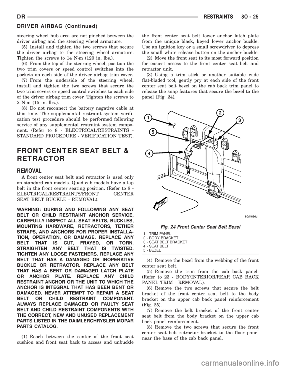
(3) Using a trim stick or another suitable wide
flat-bladed tool, gently pry at each side of the front
center seat belt bezel on the cab back trim panel to
release the snap features that secure the bezel to the
panel (Fig. 24).
(4) Remove the bezel from the webbing of the front
center seat belt.
(5) Remove the trim from the cab back panel.
(Refer to 23 - BODY/INTERIOR/REAR CAB BACK
PANEL TRIM - REMOVAL).
(6) Remove the two screws that secure the belt
bracket of the front center seat belt to the body
bracket on the upper cab back panel reinforcement
(Fig. 25).
(7) Remove the belt bracket of the front center
seat belt from the body bracket on the upper cab
back panel reinforcement.
(8) Remove the two screws that secure the front
center seat belt retractor bracket to the floor panel
near the base of the cab back panel.
Fig. 24 Front Center Seat Belt Bezel
1 - TRIM PANEL
2 - BODY BRACKET
3 - SEAT BELT BRACKET
4 - SEAT BELT
5 - BEZEL
DRRESTRAINTS 8O - 25
DRIVER AIRBAG (Continued)