2003 DODGE RAM ECO mode
[x] Cancel search: ECO modePage 679 of 2895
²Wipe-After-Wash Mode- When the control
knob on the control stalk of the multi-function switch
is depressed to the momentary Wash position for
more than about one-half second with the wiper sys-
tem turned Off, the washer pump/motor and the wip-
ers will operate for as long as the washer switch is
held closed up to about thirty seconds, then provide
several additional wipe cycles after the control knob
is released before parking the wiper blades near the
base of the windshield. If the control knob is held in
the depressed Wash position for more than about
thirty seconds, washer system operation will be sus-
pended until the control knob is released for about
two seconds then cycled back to the Wash position.
OPERATION
The wiper and washer system is designed to pro-
vide the vehicle operator with a convenient, safe, and
reliable means of maintaining visibility through the
windshield glass. The various components of this sys-
tem are designed to convert electrical energy pro-
duced by the vehicle electrical system into the
mechanical action of the wiper blades to wipe the
outside surface of the glass, as well as into the
hydraulic action of the washer system to apply
washer fluid stored in an on-board reservoir to the
area of the glass to be wiped. When combined, these
components provide the means to effectively main-
tain clear visibility for the vehicle operator by remov-
ing excess accumulations of rain, snow, bugs, mud, or
other minor debris from the outside windshield glass
surface that might be encountered while driving the
vehicle under numerous types of inclement operating
conditions.
The vehicle operator initiates all wiper and washer
system functions with the control knob on the end of
the control stalk of the multi-function switch that
extends from the left side of the steering column, just
below the steering wheel. Rotating the control knob
on the end of the control stalk, selects the Off, Delay,
Low, or High wiper system operating modes. In the
Delay mode, the control knob also allows the vehicle
operator to select from one of five intermittent wipe
Delay intervals. Depressing the control knob towards
the steering column actuates the momentary washer
system switch, which selects the Wash, Wipe-After-
Wash, and Pulse Wipe Modes depending upon when
and how long the switch is held closed. The multi-
function switch provides hard wired resistor multi-
plexed inputs to the instrument cluster for all of the
wiper and washer system functions. The instrument
cluster then sends electronic messages to the Front
Control Module (FCM) over the Programmable Com-
munications Interface (PCI) data bus requesting the
appropriate wiper and washer system operating
modes.Wiper and washer system operation are completely
controlled by the instrument cluster and FCM logic
circuits, and that logic will only allow these systems
to operate when the ignition switch is in the Acces-
sory or On positions. Battery current is directed from
a B(+) fuse in the Integrated Power Module (IPM) to
the wiper on/off relay and the wiper high/low relay in
the IPM through a fused B(+) circuit. The FCM uses
low side drivers to control wiper system operation by
energizing or de-energizing the wiper high/low and
wiper on/off relays. The FCM uses a high side driver
to control the operation of the washer pump motor
unit. The multi-function switch circuitry receives a
clean ground output from the instrument cluster on a
multi-function switch return circuit, then provides
resistor multiplexed inputs to the instrument cluster
on an intermittent wipe mux circuit to indicate the
selected wiper system mode and on a wash/beam
select mux circuit to indicate the selected washer sys-
tem mode.
The hard wired circuits and components of the
wiper and washer system may be diagnosed and
tested using conventional diagnostic tools and proce-
dures. However, conventional diagnostic methods
may not prove conclusive in the diagnosis of the
instrument cluster, the FCM, or the electronic mes-
sage inputs to or outputs from the instrument cluster
or FCM that control the wiper and washer system
operating modes. The most reliable, efficient, and
accurate means to diagnose the instrument cluster or
the FCM inputs and outputs related to the various
wiper and washer system operating modes requires
the use of a DRBIIItscan tool. Refer to the appro-
priate diagnostic information.
OPERATING MODES
Following are paragraphs that briefly describe the
operation of each of the wiper and washer system
operating modes.
CONTINUOUS WIPE MODE
When the Low position of the control knob on the
control stalk of the multi-function switch is selected
the instrument cluster sends an electronic wiper
switch low message to the FCM, then the FCM ener-
gizes the wiper on/off relay. This directs battery cur-
rent through the normally open contacts of the
energized wiper on/off relay and the normally closed
contacts of the de-energized wiper high/low relay to
the low speed brush of the wiper motor, causing the
wipers to cycle at low speed.
When the High position of the control knob is
selected the instrument cluster sends an electronic
wiper switch high message to the FCM, then the
FCM energizes both the wiper on/off relay and the
wiper high/low relay. This directs battery current
8R - 4 WIPERS/WASHERSDR
WIPERS/WASHERS (Continued)
Page 680 of 2895
through the normally open contacts of the energized
wiper on/off relay and the normally open contacts of
the energized wiper high/low relay to the high speed
brush of the wiper motor, causing the wipers to cycle
at high speed.
When the Off position of the multi-function switch
control knob is selected, the instrument cluster sends
an electronic wiper switch off message to the FCM. If
the wiper motor was operating at high speed, the
FCM immediately de-energizes the wiper high/low
relay causing the wiper motor to return to low speed
operation. Then one of two events will occur. The
event that occurs depends upon the position of the
wiper blades on the windshield at the moment that
the control knob Off position is selected.
If the wiper blades are in the down position on the
windshield when the Off position is selected, the
park switch that is integral to the wiper motor is
closed to ground and provides a hard wired park
switch sense input to the FCM. The FCM then de-en-
ergizes the wiper on/off relay and the wiper motor
ceases to operate. If the wiper blades are not in the
down position on the windshield at the moment the
Off position is selected, the park switch is an open
circuit and the FCM keeps the wiper on/off relay
energized, which causes the wiper motor to continue
running at low speed until the wiper blades are in
the down position on the windshield and the park
switch input to the FCM is again closed to ground.
INTERMITTENT WIPE MODE
When the control knob on the control stalk of the
multi-function switch is moved to one of the Delay
interval positions the instrument cluster sends an
electronic wiper switch delay message to the FCM,
then the FCM electronic intermittent wipe logic cir-
cuit responds by calculating the correct length of
time between wiper sweeps based upon the selected
delay interval input. The FCM monitors the changing
state of the wiper motor park switch through a hard
wired park switch sense input. This input allows the
FCM to determine the proper intervals at which to
energize and de-energize the wiper on/off relay to
operate the wiper motor intermittently for one low
speed cycle at a time.
The FCM logic is also programmed to provide vehi-
cle speed sensitivity to the selected intermittent wipe
delay intervals. In order to provide this feature the
FCM monitors electronic vehicle speed messages
from the Powertrain Control Module (PCM) and dou-
bles the selected delay interval whenever the vehicle
speed is about sixteen kilometers-per-hour (ten miles-
per-hour) or less.PULSE WIPE MODE
When the control knob on the control stalk of the
multi-function switch is depressed to the momentary
Wash position for less than about one-half second,
the instrument cluster sends an electronic washer
switch message to the FCM, then the FCM the ener-
gizes the wiper on/off relay for one complete wipe
cycle. The FCM de-energizes the relay when the state
of the park switch sense changes to ground, parking
the wiper blades near the base of the windshield.
WASH MODE
When the control knob on the control stalk of the
multi-function switch is depressed to the momentary
Wash position for more than about one-half second,
the instrument cluster sends an electronic washer
switch message to the FCM, then the FCM directs
battery current to the washer pump/motor unit. This
will cause the washer pump/motor unit to be ener-
gized for as long as the Wash switch is held closed up
to about thirty seconds, and to de-energize when the
front Wash switch is released.
When the control knob is depressed to the momen-
tary Wash position while the wiper system is operat-
ing in one of the Delay interval positions, the washer
pump/motor operation is the same. However, the
FCM also energizes the wiper on/off relay to override
the selected delay interval and operate the wiper
motor in a continuous low speed mode for as long as
the control knob is held depressed, then de-energizes
the relay and reverts to the selected delay mode
interval several wipe cycles after the control knob is
released. If the control knob is held depressed for
more than about thirty seconds, the FCM will sus-
pend washer pump/motor operation until the knob is
released for about two seconds, then cycled back to
the Wash position.
WIPE-AFTER-WASH MODE
When the control knob on the control stalk of the
multi-function switch is depressed to the momentary
Wash position for more than about one-half second
while the wiper system is not operating, the instru-
ment cluster sends an electronic washer switch mes-
sage to the FCM, then the FCM the directs battery
current to the washer pump/motor unit and energizes
the wiper on/off relay. This will cause the washer
pump/motor unit to be energized and operate the
wiper motor in a continuous low speed mode for as
long as the Wash switch is held closed up to about
thirty seconds. When the control knob is released,
the FCM de-energizes the washer pump/motor unit,
but allows the wiper motor to operate for several
additional wipe cycles before it de-energizes the
wiper on/off relay and parks the wiper blades near
the base of the windshield.
DRWIPERS/WASHERS 8R - 5
WIPERS/WASHERS (Continued)
Page 681 of 2895
If the control knob is held depressed for more than
about thirty seconds, the FCM will suspend washer
pump/motor operation until the knob is released for
about two seconds, then cycled back to the Wash
position; however, the wipers will continue to operate
for as long as the Wash switch is held closed. The
FCM monitors the changing state of the wiper motor
park switch through a hard wired wiper park switch
sense circuit input. This input allows the FCM to
count the number of wipe cycles that occur after the
Wash switch is released, and to determine the proper
interval at which to de-energize the wiper on/off
relay to complete the wipe-after-wash mode cycle.
DIAGNOSIS AND TESTING - WIPER &
WASHER SYSTEM
If the wiper motor operates, but the wipers do not
move on the windshield, replace the faulty wiper
module. If the washer pump/motor operates, but no
washer fluid is dispensed on the glass; or, if the wip-
ers operate, but chatter, lift, or do not clear the glass,
clean and inspect the wiper and washer system com-
ponents as required. (Refer to 8 - ELECTRICAL/
WIPERS/WASHERS - CLEANING) and (Refer to 8 -
ELECTRICAL/WIPERS/WASHERS - INSPECTION).
For diagnosis and testing of the multi-function
switch (Refer to 8 - ELECTRICAL/LAMPS/LIGHT-
ING - EXTERIOR/MULTI-FUNCTION SWITCH -
DIAGNOSIS AND TESTING). Refer to the appropri-
ate wiring information. The wiring information
includes wiring diagrams, proper wire and connector
repair procedures, details of wire harness routing
and retention, connector pin-out information and
location views for the various wire harness connec-
tors, splices and grounds.
The hard wired circuits and components of the
wiper and washer system may be diagnosed and
tested using conventional diagnostic tools and proce-
dures. However, conventional diagnostic methods
may not prove conclusive in the diagnosis of the
instrument cluster, the Front Control Module (FCM),
or the electronic message inputs to or outputs from
the instrument cluster and the FCM that control the
various wiper and washer system operating modes.
The most reliable, efficient, and accurate means to
diagnose the instrument cluster, the FCM, or the
electronic message inputs and outputs related to the
various wiper and washer system operating modes
requires the use of a DRBIIItscan tool. Refer to the
appropriate diagnostic information.
WARNING: ON VEHICLES EQUIPPED WITH AIR-
BAGS, DISABLE THE SUPPLEMENTAL RESTRAINT
SYSTEM BEFORE ATTEMPTING ANY STEERING
WHEEL, STEERING COLUMN, DRIVER AIRBAG,
PASSENGER AIRBAG, SEAT BELT TENSIONER,SIDE CURTAIN AIRBAG, OR INSTRUMENT PANEL
COMPONENT DIAGNOSIS OR SERVICE. DISCON-
NECT AND ISOLATE THE BATTERY NEGATIVE
(GROUND) CABLE, THEN WAIT TWO MINUTES FOR
THE SYSTEM CAPACITOR TO DISCHARGE BEFORE
PERFORMING FURTHER DIAGNOSIS OR SERVICE.
THIS IS THE ONLY SURE WAY TO DISABLE THE
SUPPLEMENTAL RESTRAINT SYSTEM. FAILURE TO
TAKE THE PROPER PRECAUTIONS COULD
RESULT IN ACCIDENTAL AIRBAG DEPLOYMENT
AND POSSIBLE PERSONAL INJURY.
CLEANING - WIPER & WASHER SYSTEM
WIPER SYSTEM
The squeegees of wiper blades exposed to the ele-
ments for a long time tend to lose their wiping effec-
tiveness. Periodic cleaning of the squeegees is
suggested to remove any deposits of salt or road film.
The wiper blades, arms, and windshield glass should
only be cleaned using a sponge or soft cloth and
windshield washer fluid, a mild detergent, or a non-
abrasive cleaner. If the wiper blades continue to
leave streaks, smears, hazing, or beading on the
glass after thorough cleaning of the squeegees and
the glass, the entire wiper blade assembly must be
replaced.
CAUTION: Protect the rubber squeegees of the
wiper blades from any petroleum-based cleaners,
solvents, or contaminants. These products can rap-
idly deteriorate the rubber squeegees.
WASHER SYSTEM
If the washer system is contaminated with foreign
material, drain the washer reservoir by removing the
washer pump/motor from the reservoir. Clean foreign
material from the inside of the washer pump/motor
inlet filter screen and the washer reservoir using
clean washer fluid, a mild detergent, or a non-abra-
sive cleaner. Flush foreign material from the washer
system plumbing by first disconnecting the washer
hoses from the washer nozzles, then running the
washer pump/motor to run clean washer fluid or
water through the system. Plugged or restricted
washer nozzles should be carefully back-flushed
using compressed air. If the washer nozzle obstruc-
tion cannot be cleared, replace the washer nozzle.
CAUTION: Never introduce petroleum-based clean-
ers, solvents, or contaminants into the washer sys-
tem. These products can rapidly deteriorate the
rubber seals and hoses of the washer system, as
well as the rubber squeegees of the wiper blades.
8R - 6 WIPERS/WASHERSDR
WIPERS/WASHERS (Continued)
Page 686 of 2895
(6) Remove the washer fluid level switch from the
washer reservoir.
(7) Remove the rubber grommet seal from the
washer fluid level switch mounting hole in the
washer reservoir and discard.
INSTALLATION
(1) Install a new rubber grommet seal into the
washer fluid level switch mounting hole in the
washer reservoir. Always use a new rubber grommet
seal on the reservoir.
(2) Insert the float of the washer fluid level switch
through the rubber grommet seal and into the
washer reservoir. The connector receptacle of the
washer fluid level switch should be pointed upward.
(3) Using hand pressure, press firmly and evenly
on the washer fluid level switch mounting flange
until the barbed nipple is fully seated in the rubber
grommet seal in the washer reservoir mounting hole.
(4) Reconnect the right (except V-10 and diesel
engine) or left (V-10 and diesel engine only) head-
lamp and dash wire harness connector for the washer
fluid level switch to the switch connector receptacle
(Fig. 7) or (Fig. 8).
(5) Reconnect the removed washer hose to the
barbed outlet nipple of the washer pump/motor unit.
(6) Refill the washer reservoir with the washer
fluid drained from the reservoir during the removal
procedure.
(7) Reconnect the battery negative cable.
(8) Close and latch the hood.
WASHER HOSES/TUBES
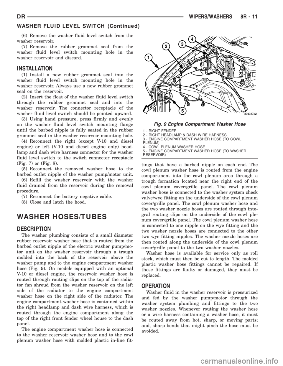
DESCRIPTION
The washer plumbing consists of a small diameter
rubber reservoir washer hose that is routed from the
barbed outlet nipple of the electric washer pump/mo-
tor unit on the washer reservoir through a trough
molded into the back of the reservoir above the
washer pump and to the engine compartment washer
hose (Fig. 9). On models equipped with an optional
V-10 or diesel engine, the reservoir washer hose is
routed through routing clips on the top of the radia-
tor fan shroud from the washer reservoir on the left
side of the radiator to the engine compartment
washer hose on the right side of the radiator. The
engine compartment washer hose is contained within
the right headlamp and dash wire harness, which is
routed through the engine compartment along the
top of the right front fender wheel house to the dash
panel.
The engine compartment washer hose is connected
to the washer reservoir washer hose and to the cowl
plenum washer hose with molded plastic in-line fit-tings that have a barbed nipple on each end. The
cowl plenum washer hose is routed from the engine
compartment into the cowl plenum area through a
trough formation located near the right end of the
cowl plenum cover/grille panel. The cowl plenum
washer hose is connected to the washer system check
valve/wye fitting on the underside of the cowl plenum
cover/grille panel. The cowl plenum washer hose and
the two washer nozzle hoses are routed through inte-
gral routing clips on the underside of the cowl ple-
num cover/grille panel. The cowl plenum washer hose
is connected to one nipple on the wye fitting and the
two washer nozzle hoses are connected to the other
two wye fitting nipples. The washer nozzle hoses are
then routed along the underside of the cowl plenum
cover/grille panel to the two washer nozzles.
Washer hose is available for service only as roll
stock, which must then be cut to length. The molded
plastic washer hose fittings cannot be repaired. If
these fittings are faulty or damaged, they must be
replaced.
OPERATION
Washer fluid in the washer reservoir is pressurized
and fed by the washer pump/motor through the
washer system plumbing and fittings to the two
washer nozzles. Whenever routing the washer hose
or a wire harness containing a washer hose, it must
be routed away from hot, sharp, or moving parts;
and, sharp bends that might pinch the hose must be
avoided.
Fig. 9 Engine Compartment Washer Hose
1 - RIGHT FENDER
2 - RIGHT HEADLAMP & DASH WIRE HARNESS
3 - ENGINE COMPARTMENT WASHER HOSE (TO COWL
PLENUM)
4 - COWL PLENUM WASHER HOSE
5 - ENGINE COMPARTMENT WASHER HOSE (TO WASHER
RESERVOIR)
DRWIPERS/WASHERS 8R - 11
WASHER FLUID LEVEL SWITCH (Continued)
Page 690 of 2895

WASHER RESERVOIR
DESCRIPTION
Except on models equipped with an optional V-10
or diesel engine, the molded plastic washer fluid res-
ervoir is mounted on the right rearward facing sur-
face of the cooling module radiator shroud in the
engine compartment (Fig. 14). On models with the
V-10 or diesel engine, the molded plastic washer fluid
reservoir is mounted on the rearward facing surface
of the left vertical member of the radiator support in
the engine compartment. The reservoir is a molded
unit constructed of a translucent plastic that allows
the washer fluid level to be inspected without remov-
ing the washer reservoir cap. The most visible com-
ponent of the washer reservoir is the filler cap unit,
which is secured to and hinges on a hook feature
that is integral to the filler neck near the top of the
reservoir. The bright yellow plastic filler cap snaps
over the filler neck opening and seals the reservoiropening with an integral rubber gasket. The filler
cap is labeled with an International Control and Dis-
play Symbol icon for ªWindshield Washerº and the
text ªWasher Fluid Onlyº that are molded into it and
highlighted in black against the yellow plastic cap for
visibility.
There are dedicated holes near the bottom of the
rearward facing side of the reservoir provided for the
mounting of the washer pump/motor unit and the
washer fluid level switch. A snap post receptacle
molded into the reservoir allows for mounting of the
washer pump without the use of fasteners. The res-
ervoir also features an integral hose routing trough
on its rearward facing side. Except on models with a
V-10 or diesel engine, the washer reservoir is secured
to the cooling module radiator shroud with three
integral tabs, two at the bottom and one at the top.
The two bottom tabs are inserted into two slots near
the bottom of the shroud, while the upper tab slides
into an integral channel-like slot near the top of the
shroud. A molded lock feature on the forward facing
surface of the reservoir engages a molded depression
on the rearward facing surface of the radiator shroud
when the reservoir is fully seated on the shroud,
locking the unit securely in place. On models with a
V-10 or diesel engine, the washer reservoir is secured
with two screws through integral mounting tabs to
the left vertical member of the radiator support. On
many models, a molded plastic coolant recovery con-
tainer or a coolant pressure container must be
detached from the top of the cooling module and
moved aside to access the washer fluid reservoir for
service. This may be accomplished without opening
or draining the engine cooling system.
OPERATION
The washer fluid reservoir provides a secure,
on-vehicle storage location for a large reserve of
washer fluid for operation of the washer system. The
washer reservoir filler neck provides a clearly
marked and readily accessible point from which to
add washer fluid to the reservoir. The washer/pump
motor unit is located in a sump area near the bottom
of the reservoir to be certain that washer fluid will
be available to the pump as the fluid level in the res-
ervoir becomes depleted. The washer pump/motor
unit is mounted in the lowest position in the sump.
The washer fluid level switch is mounted just above
the sump area of the reservoir so that there will be
adequate warning to the vehicle operator that the
washer fluid level is low, well before the washer sys-
tem will no longer operate.
Fig. 14 Washer Reservoir - except V-10 & Diesel
Engine
1-TOPTAB
2 - HOOK FEATURE
3 - CAP
4 - RESERVOIR
5 - TROUGH
6 - HOSE
7 - LOCK FEATURE
8 - WASHER FLUID LEVEL SWITCH
9 - WASHER PUMP/MOTOR
10 - BOTTOM TAB (2)
DRWIPERS/WASHERS 8R - 15
Page 709 of 2895

DESCRIPTION - CIRCUIT FUNCTIONS
All circuits in the diagrams use an alpha/numeric
code to identify the wire and it's function. To identify
which circuit code applies to a system, refer to the
Circuit Identification Code Chart. This chart shows
the main circuits only and does not show the second-
ary codes that may apply to some models.
CIRCUIT IDENTIFICATION CODE CHART
CIRCUIT FUNCTION
A BATTERY FEED
B BRAKE CONTROLS
C CLIMATE CONTROLS
D DIAGNOSTIC CIRCUITS
E DIMMING ILLUMINATION
CIRCUITS
F FUSED CIRCUITS
G MONITORING CIRCUITS
(GAUGES)
H OPEN
I NOT USED
J OPEN
K POWERTRAIN CONTROL
MODULE
L EXTERIOR LIGHTING
M INTERIOR LIGHTING
N NOT USED
O NOT USED
P POWER OPTION (BATTERY
FEED)
Q POWER OPTIONS (IGNITION
FEED)
R PASSIVE RESTRAINT
S SUSPENSION/STEERING
T TRANSMISSION/TRANSAXLE/
TRANSFER CASE
U OPEN
V SPEED CONTROL, WIPER/
WASHER
W OPEN
X AUDIO SYSTEMS
Y OPEN
Z GROUNDS
DESCRIPTION - SECTION IDENTIFICATION AND
INFORMATION
The wiring diagrams are grouped into individual
sections. If a component is most likely found in a par-
ticular group, it will be shown complete (all wires,
connectors, and pins) within that group. For exam-
ple, the Auto Shutdown Relay is most likely to be
found in Group 30, so it is shown there complete. It
can, however, be shown partially in another group if
it contains some associated wiring.
Splice diagrams in Section 8W-70 show the entire
splice and provide references to other sections the
splices serves. Section 8W-70 only contains splice dia-
grams that are not shown in their entirety some-
where else in the wiring diagrams.
Section 8W-80 shows each connector and the cir-
cuits involved with that connector. The connectors
are identified using the name/number on the dia-
gram pages.
WIRING SECTION CHART
GROUP TOPIC
8W-01 thru
8W-09General information and Diagram
Overview
8W-10 thru
8W-19Main Sources of Power and
Vehicle Grounding
8W-20 thru
8W-29Starting and Charging
8W-30 thru
8W-39Powertrain/Drivetrain Systems
8W-40 thru
8W-49Body Electrical items and A/C
8W-50 thru
8W-59Exterior Lighting, Wipers and
Trailer Tow
8W-60 thru
8W-69Power Accessories
8W-70 Splice Information
8W-80 Connector Pin Outs
8W-91 Connector, Ground and Splice
Locations
8W - 01 - 6 8W-01 WIRING DIAGRAM INFORMATIONDR
WIRING DIAGRAM INFORMATION (Continued)
Page 1241 of 2895
SPECIAL TOOLS
POWER DISTRIBUTION SYSTEMS
CIGAR LIGHTER OUTLET
DESCRIPTION
On models equipped a cigar lighter outlet is
installed to the left of the center stack area in the
lower instrument panel. The cigar lighter outlet is
secured by a snap fit within the bezel.
The cigar lighter outlet, plastic cap and the knob
and heating element unit are available for service
replacement. These components cannot be repaired
and, if faulty or damaged, they must be replaced.
OPERATION
The cigar lighter consists of two major components:
a knob and heating element unit, and the cigar
lighter base or outlet shell. The receptacle shell is
connected to ground, and an insulated contact in the
bottom of the shell is connected to battery current.
The cigar lighter receives battery voltage from a fuse
in the junction block when the ignition switch is in
the Accessory or Run positions.
The cigar lighter knob and heating element are
encased within a spring-loaded housing, which also
features a sliding protective heat shield. When the
knob and heating element are inserted in the outlet
shell, the heating element resistor coil is grounded
through its housing to the outlet shell. If the cigar
lighter knob is pushed inward, the heat shield slides
up toward the knob exposing the heating element,
and the heating element extends from the housing
toward the insulated contact in the bottom of the
outlet shell.
Two small spring-clip retainers are located on
either side of the insulated contact inside the bottom
of the outlet shell. These clips engage and hold the
heating element against the insulated contact longenough for the resistor coil to heat up. When the
heating element is engaged with the contact, battery
current can flow through the resistor coil to ground,
causing the resistor coil to heat.
When the resistor coil becomes sufficiently heated,
excess heat radiates from the heating element caus-
ing the spring-clips to expand. Once the spring-clips
expand far enough to release the heating element,
the spring-loaded housing forces the knob and heat-
ing element to pop back outward to their relaxed
position. When the cigar lighter knob and element
are pulled out of the outlet shell, the protective heat
shield slides downward on the housing so that the
heating element is recessed and shielded around its
circumference for safety.
DIAGNOSIS AND TESTING - CIGAR LIGHTER
OUTLET
For complete circuit diagrams, refer toWiring
Diagrams.
(1) Check the fused B(+) fuse in the integrated
power module. If OK, go to Step 2. If not OK, repair
the shorted circuit or component as required and
replace the faulty fuse.
(2) Turn the ignition switch to the Run position.
Check for battery voltage at the fused B(+) fuse in
the integrated power module. If OK, go to Step 3. If
not OK, repair the open or short as required.
(3) Remove the cigar lighter knob and element
from the cigar lighter outlet shell. Check for continu-
ity between the inside circumference of the cigar
lighter outlet shell and a good ground. there should
be continuity. If OK, go to Step 4. If not OK, go to
Step 5.
(4) Turn the ignition switch to the Run position.
Check for battery voltage at the insulated contact
located at the back of the cigar lighter outlet shell. If
OK, replace the faulty cigar lighter knob and ele-
ment. If not OK, go to Step 5.
(5) Turn the ignition switch to the Off position.
Disconnect and isolate the battery negative cable.
Check for continuity between the ground circuit cav-
ity of the cigar lighter wire harness connector and a
good ground. There should be continuity. If OK, go to
Step 6. If not OK, repair the open ground circuit to
ground as required.
(6) Connect the battery negative cable. Turn the
ignition switch to the Accessory or Run positions.
Check for battery voltage at the fused B(+) circuit
cavity of the cigar lighter wire harness connector. If
OK, replace the faulty cigar lighter outlet. If not OK,
repair the open fused B(+) circuit to the integrated
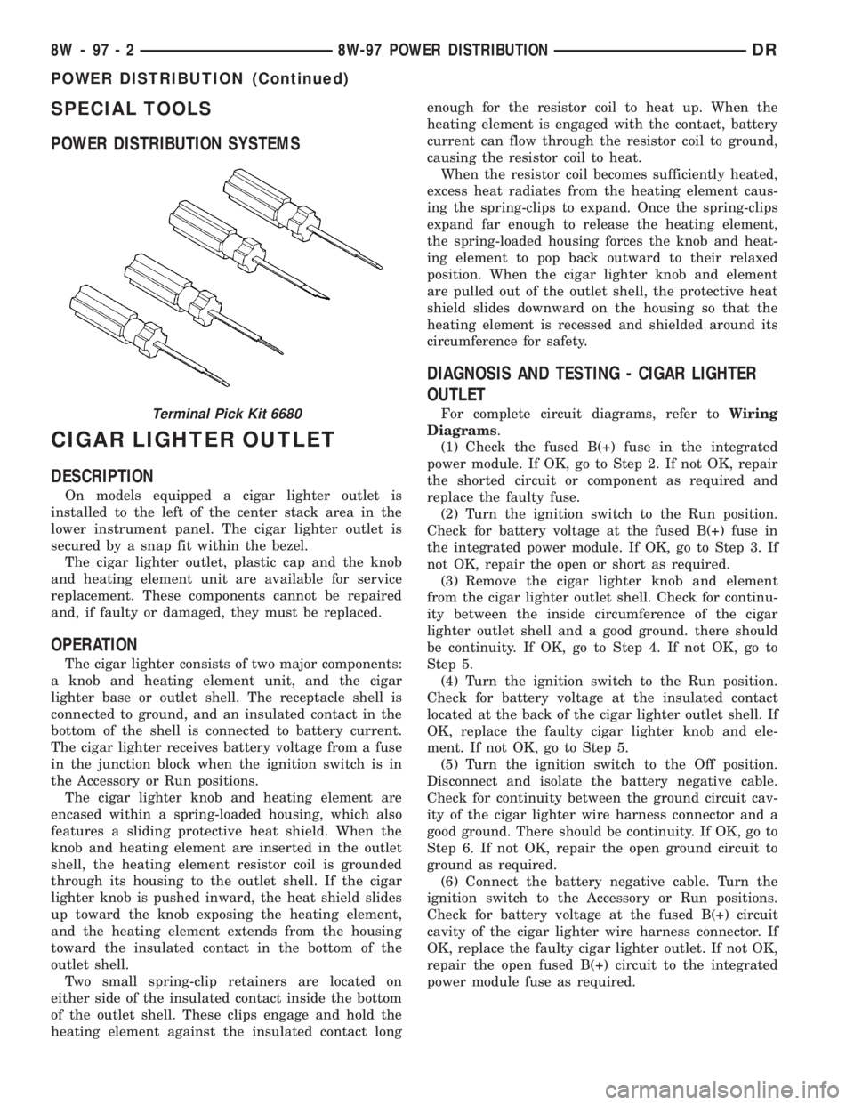
power module fuse as required.Terminal Pick Kit 6680
8W - 97 - 2 8W-97 POWER DISTRIBUTIONDR
POWER DISTRIBUTION (Continued)
Page 1245 of 2895
IOD FUSE
DESCRIPTION
All vehicles are equipped with an Ignition-Off
Draw (IOD) fuse that is disconnected within the Inte-
grated Power Module when the vehicle is shipped
from the factory. Dealer personnel are to reconnect
the IOD fuse in the Integrated Power Module as part
of the preparation procedures performed just prior to
new vehicle delivery.
A laser printed fuse layout map is integral to the
Integrated Power Module cover to ensure proper fuse
identification. The IOD fuse is a 20 ampere mini
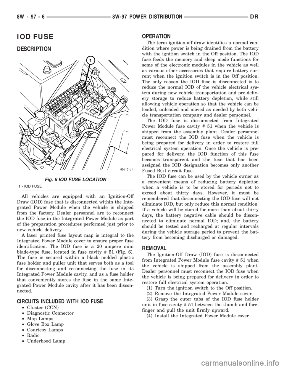
blade-type fuse, located in fuse cavity # 51 (Fig. 6).
The fuse is secured within a black molded plastic
fuse holder and puller unit that serves both as a tool
for disconnecting and reconnecting the fuse in its
Integrated Power Module cavity, and as a fuse holder
that conveniently stores the fuse in the same Inte-
grated Power Module cavity after it has been discon-
nected.
CIRCUITS INCLUDED WITH IOD FUSE
²Cluster (CCN)
²Diagnostic Connector
²Map Lamps
²Glove Box Lamp
²Courtesy Lamps
²Radio
²Underhood Lamp
OPERATION
The term ignition-off draw identifies a normal con-
dition where power is being drained from the battery
with the ignition switch in the Off position. The IOD
fuse feeds the memory and sleep mode functions for
some of the electronic modules in the vehicle as well
as various other accessories that require battery cur-
rent when the ignition switch is in the Off position.
The only reason the IOD fuse is disconnected is to
reduce the normal IOD of the vehicle electrical sys-
tem during new vehicle transportation and pre-deliv-
ery storage to reduce battery depletion, while still
allowing vehicle operation so that the vehicle can be
loaded, unloaded and moved as needed by both vehi-
cle transportation company and dealer personnel.
The IOD fuse is disconnected from Integrated
Power Module fuse cavity # 51 when the vehicle is
shipped from the assembly plant. Dealer personnel
must reconnect the IOD fuse when the vehicle is
being prepared for delivery in order to restore full
electrical system operation. Once the vehicle is pre-
pared for delivery, the IOD function of this fuse
becomes transparent and the fuse that has been
assigned the IOD designation becomes only another
Fused B(+) circuit fuse.
The IOD fuse can be used by the vehicle owner as
a convenient means of reducing battery depletion
when a vehicle is to be stored for periods not to
exceed about thirty days. However, it must be
remembered that disconnecting the IOD fuse will not
eliminate IOD, but only reduce this normal condition.
If a vehicle will be stored for more than about thirty
days, the battery negative cable should be discon-
nected to eliminate normal IOD; and, the battery
should be tested and recharged at regular intervals
during the vehicle storage period to prevent the bat-
tery from becoming discharged or damaged.
REMOVAL
The Ignition-Off Draw (IOD) fuse is disconnected
from Integrated Power Module fuse cavity # 51 when
the vehicle is shipped from the assembly plant.
Dealer personnel must reconnect the IOD fuse when
the vehicle is being prepared for delivery in order to
restore full electrical system operation.
(1) Turn the ignition switch to the Off position.
(2) Remove the Integrated Power Module cover.
(3) Grasp the outer tabs of the IOD fuse holder
unit in fuse cavity # 51 between the thumb and fore-
finger and pull the unit firmly upward.
(4) Install the Integrated Power Module cover.
Fig. 6 IOD FUSE LOCATION
1 - IOD FUSE
8W - 97 - 6 8W-97 POWER DISTRIBUTIONDR