2003 DODGE RAM ECO mode
[x] Cancel search: ECO modePage 1246 of 2895
INSTALLATION
(1) Turn the ignition switch to the Off position.
(2) Remove the Integrated Power Module cover.
(3) To install the IOD fuse, use a thumb to press
the IOD fuse holder unit in fuse cavity # 51 firmly
into the Integrated Power Module.
(4) Install the Integrated Power Module cover.
POWER OUTLET
DESCRIPTION
Two power outlets are utilized on this model. One
in the instrument panel center lower bezel and the
other in the center console. The power outlet bases
are secured by a snap fit within the instrument
panel or trim panel. A plastic protective cap snaps
into the power outlet base when the power outlet is
not being used, and hangs from the power outlet base
mount by an integral bail strap while the power out-
let is in use.
The power outlet receptacle unit and the accessory
power outlet protective cap are available for service.
The power outlet receptacle cannot be repaired and,
if faulty or damaged, it must be replaced.
OPERATION
The power outlet base or receptacle shell is con-
nected to ground, and an insulated contact in the
bottom of the shell is connected to battery current.
The power outlet receives battery voltage from a fuse
in the integrated power module at all times.
While the power outlet is very similar to a cigar
lighter base unit, it does not include the two small
spring-clip retainers inside the bottom of the recepta-
cle shell that are used to secure the cigar lighter
heating element to the insulated contact.
DIAGNOSIS AND TESTING - POWER OUTLET
For complete circuit diagrams, refer toWiring
Diagrams.
(1) Check the fused B(+) fuse in the integrated
power module. If OK, go to Step 2. If not OK, repair
the shorted circuit or component as required and
replace the faulty fuse.
(2) Check for battery voltage at the fused B(+) fuse
in the integrated power module. If OK, go to Step 3.
If not OK, repair the open fused B(+) circuit to the
battery as required.
(3) Remove the plastic protective cap from the
power outlet receptacle. Check for continuity between
the inside circumference of the power outlet recepta-
cle and a good ground. There should be continuity. If
OK, go to Step 4. If not OK, go to Step 5.(4) Check for battery voltage at the insulated con-
tact located at the back of the power outlet recepta-
cle. If not OK, go to Step 5.
(5) Disconnect and isolate the battery negative
cable. Remove the power outlet receptacle from the
instrument panel. Disconnect the wire harness con-
nector from the power outlet receptacle. Check for
continuity between the ground circuit cavity of the
power outlet wire harness connector and a good
ground. There should be continuity. If OK, go to Step
6. If not OK, repair the open ground circuit to ground
as required.
(6) Connect the battery negative cable. Check for
battery voltage at the fused B(+) circuit cavity of the
power outlet wire harness connector. If OK, replace
the faulty power outlet receptacle. If not OK, repair
the open fused B(+) circuit to the integrated power
module fuse as required.
REMOVAL
(1) Disconnect and isolate the battery negative
cable.
(2) Pull the cigar lighter knob and element out of
the cigar lighter receptacle base, or unsnap the pro-
tective cap from the power outlet receptacle base.
(3) Look inside the cigar lighter or power outlet
receptacle base and note the position of the rectangu-
lar retaining bosses of the mount that secures the
receptacle base to the panel (Fig. 7).
(4) Insert a pair of external snap ring pliers into
the cigar lighter or power outlet receptacle base and
engage the tips of the pliers with the retaining
bosses of the mount.
(5) Squeeze the pliers to disengage the mount
retaining bosses from the receptacle base and, using
a gentle rocking motion, pull the pliers and the
receptacle base out of the mount.
(6) Pull the receptacle base away from the instru-
ment panel far enough to access the instrument
panel wire harness connector.
(7) Disconnect the instrument panel wire harness
connector from the cigar lighter or power outlet
receptacle base connector receptacle.
(8) Remove the cigar lighter or power outlet mount
from the instrument panel.
INSTALLATION
(1) Reconnect the instrument panel wire harness
connector to the cigar lighter or power outlet recep-
tacle base connector receptacle.
(2) Install the cigar lighter or power outlet mount
into the instrument panel.
(3) Align the splines on the outside of the cigar
lighter or power outlet receptacle base connector
receptacle with the grooves on the inside of the
mount.
DR8W-97 POWER DISTRIBUTION 8W - 97 - 7
IOD FUSE (Continued)
Page 1483 of 2895
(3) Recover refrigerant from a/c system, if
equipped (Refer to 24 - HEATING & AIR CONDI-
TIONING/PLUMBING - STANDARD PROCEDURE).
(4) Remove the a/c condenser, if equipped (Refer to
24 - HEATING & AIR CONDITIONING/PLUMBING/
A/C CONDENSER - REMOVAL).
(5) Remove the transmission oil cooler (Refer to 7 -
COOLING/TRANSMISSION/TRANS COOLER -
REMOVAL).
(6) Remove the washer bottle from the fan shroud.
(7) Remove the viscous fan/drive (Refer to 7 -
COOLING/ENGINE/RADIATOR FAN - REMOVAL).
(8) Remove radiator (Refer to 7 - COOLING/EN-
GINE/RADIATOR - REMOVAL).
(9) Remove the upper crossmember and top core
support.
(10) Remove the accessory drive belt (Refer to 7 -
COOLING/ACCESSORY DRIVE/DRIVE BELTS -
REMOVAL).
(11) Remove the A/C compressor with the lines
attached. Secure compressor out of the way.
(12) Remove generator assembly (Refer to 8 -
ELECTRICAL/CHARGING/GENERATOR - REMOV-
AL).
(13) Remove the air cleaner resonator and duct
work as an assembly.
(14) Disconnect the throttle linkage (Refer to 14 -
FUEL SYSTEM/FUEL INJECTION/THROTTLE
CONTROL CABLE - REMOVAL).
(15) Remove throttle body (Refer to 14 - FUEL
SYSTEM/FUEL INJECTION/THROTTLE BODY -
REMOVAL).
(16) Remove the intake manifold (Refer to 9 -
ENGINE/MANIFOLDS/INTAKE MANIFOLD -
REMOVAL).
(17) Remove the distributor cap and wiring.
(18) Disconnect the heater hoses.
(19) Disconnect the power steering hoses, if
equipped.
(20) Perform the Fuel System Pressure Release
procedure (Refer to 14 - FUEL SYSTEM/FUEL
DELIVERY - STANDARD PROCEDURE).
(21) Disconnect the fuel supply line (Refer to 14 -
FUEL SYSTEM/FUEL DELIVERY/QUICK CON-
NECT FITTING - STANDARD PROCEDURE).
(22) On Manual Transmission vehicles, remove the
shift lever (Refer to 21 - TRANSMISSION/TRANS-
AXLE/MANUAL/SHIFT COVER - REMOVAL).
(23) Raise and support the vehicle on a hoist and
drain the engine oil.
(24) Remove engine front mount thru-bolt nuts.
(25) Disconnect the transmission oil cooler lines
from their retainers at the oil pan bolts.
(26) Disconnect exhaust pipe at manifolds.(27) Disconnect the starter wires. Remove starter
motor (Refer to 8 - ELECTRICAL/STARTING/
STARTER MOTOR - REMOVAL).
(28) Remove the dust shield and transmission
inspection cover.
(29) Remove drive plate to converter bolts (Auto-
matic transmission equipped vehicles).
(30) Remove transmission bell housing to engine
block bolts.
(31) Lower the vehicle.
(32) Install an engine lifting fixture.
(33) Separate engine from transmission, remove
engine from vehicle, and install engine assembly on a
repair stand.
INSTALLATION
(1) Remove engine from the repair stand and posi-
tion in the engine compartment. Position the thru-
bolt into the support cushion brackets.
(2) Install engine lifting device.
(3) Lower engine into compartment and align
engine with transmission:
²Manual Transmission: Align clutch disc assem-
bly (if disturbed). Install transmission input shaft
into clutch disc while mating engine and transmis-
sion surfaces. Install two transmission to engine
block mounting bolts finger tight.
²Automatic Transmission: Mate engine and trans-
mission and install two transmission to engine block
mounting bolts finger tight.
(4) Lower engine assembly until engine mount
through bolts rest in mount perches.
(5) Install remaining transmission to engine block
mounting bolts and tighten.
(6) Tighten engine mount through bolts.
(7) Install drive plate to torque converter bolts.
(Automatic transmission models)
(8) Install the dust shield and transmission cover.
(9) Install the starter and connect the starter
wires (Refer to 8 - ELECTRICAL/STARTING/
STARTER MOTOR - INSTALLATION).
(10) Install exhaust pipe to manifold.
(11) Install the transmission cooler line brackets to
the oil pan.
(12) Install the drain plug and tighten to 34 N´m
(25 ft. lbs.) torque.
(13) Lower the vehicle.
(14) Remove engine lifting fixture.
(15) On Manual Transmission vehicles, install the
shift lever (Refer to 21 - TRANSMISSION/TRANS-
AXLE/MANUAL/SHIFT COVER - INSTALLATION).
(16) Connect the fuel supply line (Refer to 14 -
FUEL SYSTEM/FUEL DELIVERY/QUICK CON-
NECT FITTING - STANDARD PROCEDURE).
(17) Connect the power steering hoses, if equipped.
(18) Connect the heater hoses.
9 - 234 ENGINE - 5.9LDR
ENGINE - 5.9L (Continued)
Page 1539 of 2895
²Installing an insert into the tapped hole to bring
the hole back to its original thread size.
STANDARD PROCEDUREÐHYDROSTATIC
LOCK
CAUTION: DO NOT use the starter motor to rotate
the crankshaft. Severe damage could occur.
When an engine is suspected of hydrostatic lock
(regardless of what caused the problem), follow the
steps below.
(1) Disconnect the negative cable(s) from the bat-
tery.
(2) Inspect air cleaner, induction system, and
intake manifold to ensure system is dry and clear of
foreign material.
(3) Place a shop towel around the fuel injectors to
catch any fluid that may possibly be under pressure
in the cylinder head. Remove the fuel injectors (Refer
to 14 - FUEL SYSTEM/FUEL INJECTION/FUEL
INJECTOR - REMOVAL).
(4) With all injectors removed, rotate the crank-
shaft using the crankshaft barring tool (PN 7471±B).
(5) Identify the fluid in the cylinders (coolant, fuel,
oil, etc.).
(6) Be sure all fluid has been removed from the
cylinders.
(7) Repair engine or components as necessary to
prevent this problem from occurring again.
(8) Squirt a small amount of engine oil into the
cylinders to lubricate the walls. This will prevent
damage on restart.
(9) Install fuel injectors (Refer to 14 - FUEL SYS-
TEM/FUEL INJECTION/FUEL INJECTOR -
INSTALLATION).
(10) Drain engine oil. Remove and discard the oil
filter (Refer to 9 - ENGINE/LUBRICATION/OIL FIL-
TER - REMOVAL).
(11) Install the drain plug. Tighten the plug to 50
N´m (37 ft. lbs.) torque.
(12) Install a new oil filter (Refer to 9 - ENGINE/
LUBRICATION/OIL FILTER - INSTALLATION).
(13) Fill engine crankcase with the specified
amount and grade of oil (Refer to LUBRICATION &
MAINTENANCE/FLUID TYPES - SPECIFICA-
TIONS).
(14) Connect the negative cable(s) to the battery.
(15) Start the engine and check for any leaks.
REMOVAL
REMOVALÐENGINE
(1) Disconnect both battery negative cables.
(2) Disconnect engine grid heater harness at grid
heater relays.(3) Disconnect electrical connections from rear of
alternator.
(4) Recover A/C refrigerant. (Refer to 24 - HEAT-
ING & AIR CONDITIONING/PLUMBING - STAN-
DARD PROCEDURE).
(5) Raise vehicle on a hoist.
(6) Drain engine coolant (Refer to 7 - COOLING -
STANDARD PROCEDURE).
(7) Remove engine oil drain plug and drain engine
oil.
(8) Remove fan/drive assembly. Refer to Section 7
± Fan/Drive Removal
(9) Remove radiator upper hose.
(10) Remove upper fan shroud mounting bolts.
(11) Disconnect the coolant recovery bottle hose
from the radiator fill neck and remove bottle.
(12) Using a 36mm wrench, remove viscous fan/
drive assembly. (Refer to 7 - COOLING/ENGINE/RA-
DIATOR FAN - REMOVAL).
(13) Remove cooling fan and shroud together.
(14) Disconnect heater core supply and return
hoses from the cylinder head fitting and coolant pipe.
(15) Raise vehicle on a hoist.
(16) Remove transmission and transfer case (if
equipped).
(17) Disconnect exhaust pipe from turbocharger
extension pipe.
(18) Disconnect engine harness to vehicle harness
connectors.
(19) Remove starter motor (Refer to 8 - ELECTRI-
CAL/STARTING/STARTER MOTOR - REMOVAL).
(20) Remove flywheel/flexplate.
(21) Remove transmission adapter
(22) Disconnect A/C suction/discharge hose from
the rear of the A/C compressor.
(23) Lower vehicle.
(24) Disconnect lower radiator hose from radiator
outlet.
(25) Automatic transmission models:
(26) Disconnect transmission oil cooler lines from
in front of radiator using special tool #6931
(27) Remove radiator. (Refer to 7 - COOLING/EN-
GINE/RADIATOR - REMOVAL).
(28) If A/C equipped, disconnect A/C condenser
refrigerant lines.
(29) Disconnect charge air cooler piping.
(30) Remove charge air cooler mounting bolts.
(31) Remove charge air cooler (and A/C condenser
if equipped) from vehicle.
(32) Remove damper and speed indicator ring from
front of engine.
(33) Disconnect engine block heater connector.
(34) Disconnect A/C compressor and pressure sen-
sor electrical connectors.
9 - 290 ENGINE 5.9L DIESELDR
ENGINE 5.9L DIESEL (Continued)
Page 1566 of 2895
CAMSHAFT & BEARINGS (IN
BLOCK)
REMOVAL
REMOVALÐCAMSHAFT BEARINGS
NOTE: Measure the diameter of each bore. If the
camshaft bore for the first or rear cam bushing is
worn beyond the limit, install a new service bush-
ing. Inspect the rest of the camshaft bores for dam-
age or excessive wear.If the bores without a
bushing are worn beyond the limit, the engine must
be removed for machining and installation of ser-
vice bushings. If badly worn, replace the cylinder
block.
(1) Remove the camshaft (Refer to 9 - ENGINE/
ENGINE BLOCK/CAMSHAFT & BEARINGS (IN
BLOCK) - REMOVAL).
(2) Remove the bushing from the No.1 bore and
No.7 using a universal cam bushing tool.
(3) Mark the cylinder block so you can align the oil
hole in the cylinder block with the oil hole in the
bushing.
REMOVAL - CAMSHAFT
(1) Disconnect both battery negative cables.
(2) Recover A/C refrigerant (if A/C equipped) (Refer
to 24 - HEATING & AIR CONDITIONING/PLUMB-
ING - STANDARD PROCEDURE).
(3) Raise vehicle on hoist.
(4) Drain engine coolant into container suitable for
re-use (Refer to 7 - COOLING - STANDARD PROCE-
DURE).
(5) Lower vehicle.
(6) Remove radiator upper hose.
(7) Remove viscous fan/drive assembly and fan
shroud (Refer to 7 - COOLING/ENGINE/RADIATOR
FAN - REMOVAL).
(8) Disconnect the coolant recovery bottle hose
from the radiator filler neck.
(9) Disconnect lower radiator hose from radiator
outlet.
(10)Automatic Transmission models:Discon-
nect transmission oil cooler lines from front of radia-
tor using Special Tool 6931 (unless equipped with
finger-release disconnect).
(11) Remove radiator mounting screws and lift
radiator out of engine compartment.
(12) Remove upper radiator support panel.
(13) If A/C equipped, disconnect A/C condenser
refrigerant lines.
(14) Disconnect charge air cooler piping from the
cooler inlet and outlet.(15) Remove the two charge air cooler mounting
bolts.
(16) Remove charge air cooler (and A/C condenser
if equipped) from vehicle.
(17) Remove accessory drive belt (Refer to 7 -
COOLING/ACCESSORY DRIVE/DRIVE BELTS -
REMOVAL).
(18) Remove accessory drive belt tensioner.
(19) Remove the fan support/hub assembly.
(20) Remove crankshaft damper and speed indica-
tor ring (Refer to 9 - ENGINE/ENGINE BLOCK/VI-
BRATION DAMPER - REMOVAL).
(21) Remove the gear cover-to-housing bolts and
gently pry the cover away from the housing, taking
care not to mar the sealing surfaces. Remove dust
seal with cover.
(22) Using Special Tool 7471±B Crankshaft Bar-
ring Tool, rotate the crankshaft to align the timing
marks on the crankshaft and the camshaft gears.
(23) Remove the cylinder head cover (Refer to 9 -
ENGINE/CYLINDER HEAD/CYLINDER HEAD
COVER(S) - REMOVAL).
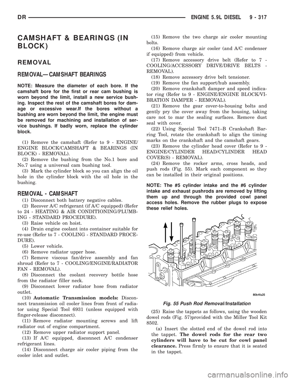
(24) Remove the rocker arms, cross heads, and
push rods (Fig. 55). Mark each component so they
can be installed in their original positions.
NOTE: The #5 cylinder intake and the #6 cylinder
intake and exhaust pushrods are removed by lifting
them up and through the provided cowl panel
access holes. Remove the rubber plugs to expose
these relief holes.
(25) Raise the tappets as follows, using the wooden
dowel rods (Fig. 57)provided with the Miller Tool Kit
8502.
(a) Insert the slotted end of the dowel rod into
the tappet.The dowel rods for the rear two
cylinders will have to be cut for cowl panel
clearance.Press firmly to ensure that it is seated
in the tappet.
Fig. 55 Push Rod Removal/Installation
DRENGINE 5.9L DIESEL 9 - 317
Page 1704 of 2895
pump.Refer to Fuel Pump - Description and
Operation for more information.
If fuel pressure at the pressure regulator exceeds
approximately 49.2 psi, an internal diaphragm opens
and excess fuel pressure is routed back into the tank
through the bottom of pressure regulator.
Both fuel filters (at bottom of fuel pump module
and within fuel pressure regulator) are designed for
extended service. They do not require normal sched-
uled maintenance. Filters should only be replaced if
a diagnostic procedure indicates to do so.
FUEL LEVEL SENDING UNIT /
SENSOR
DESCRIPTION
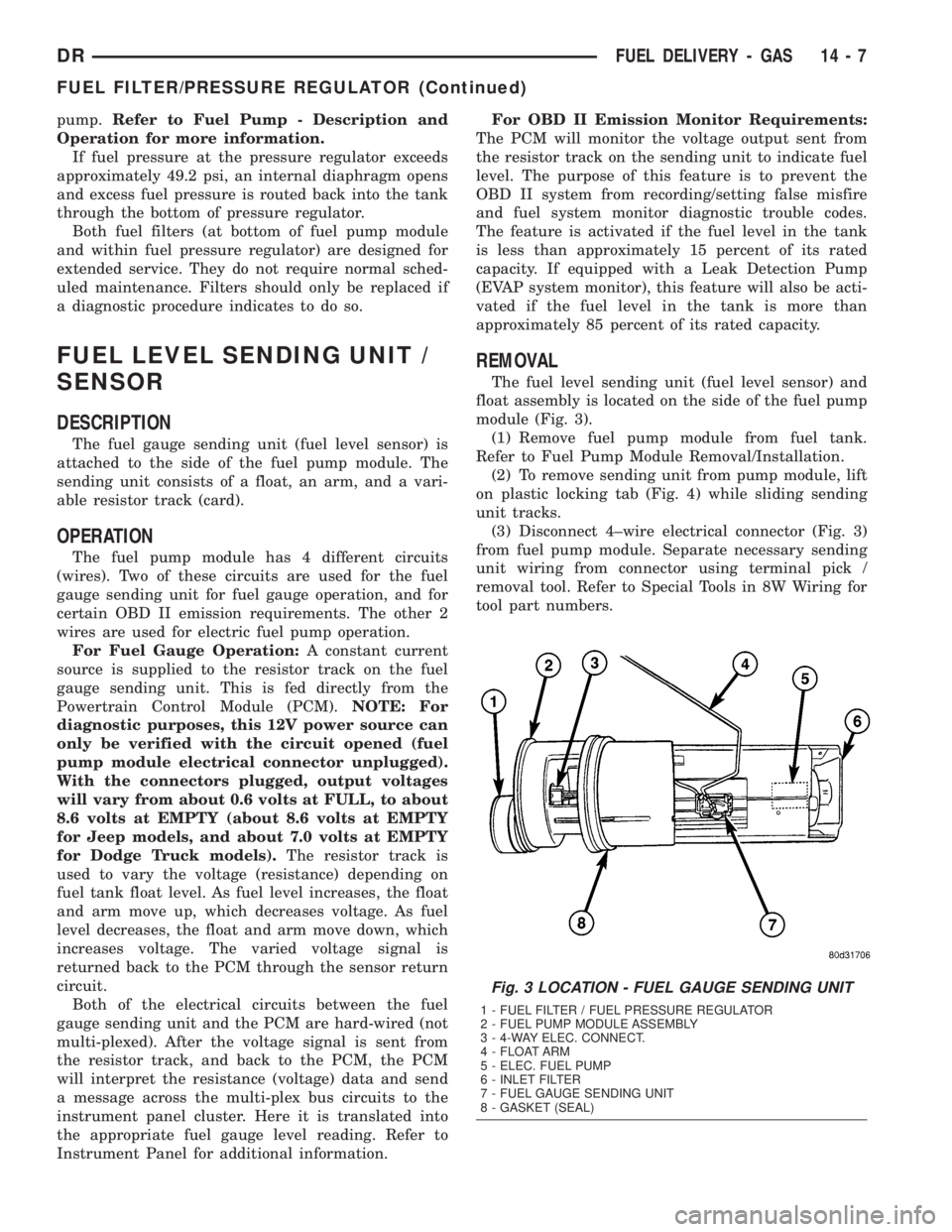
The fuel gauge sending unit (fuel level sensor) is
attached to the side of the fuel pump module. The
sending unit consists of a float, an arm, and a vari-
able resistor track (card).
OPERATION
The fuel pump module has 4 different circuits
(wires). Two of these circuits are used for the fuel
gauge sending unit for fuel gauge operation, and for
certain OBD II emission requirements. The other 2
wires are used for electric fuel pump operation.
For Fuel Gauge Operation:A constant current
source is supplied to the resistor track on the fuel
gauge sending unit. This is fed directly from the
Powertrain Control Module (PCM).NOTE: For
diagnostic purposes, this 12V power source can
only be verified with the circuit opened (fuel
pump module electrical connector unplugged).
With the connectors plugged, output voltages
will vary from about 0.6 volts at FULL, to about
8.6 volts at EMPTY (about 8.6 volts at EMPTY
for Jeep models, and about 7.0 volts at EMPTY
for Dodge Truck models).The resistor track is
used to vary the voltage (resistance) depending on
fuel tank float level. As fuel level increases, the float
and arm move up, which decreases voltage. As fuel
level decreases, the float and arm move down, which
increases voltage. The varied voltage signal is
returned back to the PCM through the sensor return
circuit.
Both of the electrical circuits between the fuel
gauge sending unit and the PCM are hard-wired (not
multi-plexed). After the voltage signal is sent from
the resistor track, and back to the PCM, the PCM
will interpret the resistance (voltage) data and send
a message across the multi-plex bus circuits to the
instrument panel cluster. Here it is translated into
the appropriate fuel gauge level reading. Refer to
Instrument Panel for additional information.For OBD II Emission Monitor Requirements:
The PCM will monitor the voltage output sent from
the resistor track on the sending unit to indicate fuel
level. The purpose of this feature is to prevent the
OBD II system from recording/setting false misfire
and fuel system monitor diagnostic trouble codes.
The feature is activated if the fuel level in the tank
is less than approximately 15 percent of its rated
capacity. If equipped with a Leak Detection Pump
(EVAP system monitor), this feature will also be acti-
vated if the fuel level in the tank is more than
approximately 85 percent of its rated capacity.
REMOVAL
The fuel level sending unit (fuel level sensor) and
float assembly is located on the side of the fuel pump
module (Fig. 3).
(1) Remove fuel pump module from fuel tank.
Refer to Fuel Pump Module Removal/Installation.
(2) To remove sending unit from pump module, lift
on plastic locking tab (Fig. 4) while sliding sending
unit tracks.
(3) Disconnect 4±wire electrical connector (Fig. 3)
from fuel pump module. Separate necessary sending
unit wiring from connector using terminal pick /
removal tool. Refer to Special Tools in 8W Wiring for
tool part numbers.
Fig. 3 LOCATION - FUEL GAUGE SENDING UNIT
1 - FUEL FILTER / FUEL PRESSURE REGULATOR
2 - FUEL PUMP MODULE ASSEMBLY
3 - 4-WAY ELEC. CONNECT.
4 - FLOAT ARM
5 - ELEC. FUEL PUMP
6 - INLET FILTER
7 - FUEL GAUGE SENDING UNIT
8 - GASKET (SEAL)
DRFUEL DELIVERY - GAS 14 - 7
FUEL FILTER/PRESSURE REGULATOR (Continued)
Page 1717 of 2895
(13) Start engine and check for leaks.
8.0L V-10
(1) Apply a small amount of engine oil to each fuel
injector o-ring. This will help in fuel rail installation.
(2) Install injector(s) and injector clip(s) to fuel
rail.
NOTE: The fuel injector electrical connectors on all
10 injectors should be facing to right (passenger)
side of vehicle (Fig. 27).
(3) Position fuel rail/fuel injector assembly to injec-
tor openings on intake manifold.
(4) Guide each injector into intake manifold. Be
careful not to tear injector o-ring.
(5) Push therightfuel rail down until fuel injec-
tors have bottomed on injector shoulder. Push the
leftfuel rail down until fuel injectors have bottomed
on injector shoulder.
(6) Install six fuel rail mounting bolts into lower
half of intake manifold. Tighten bolts to 15 N´m (136
in. lbs.) torque.
(7) Connect electrical connectors at all fuel injec-
tors. To install connector, refer to (Fig. 26). Push con-
nector onto injector (1) and then push and lock red
colored slider (2). Verify connector is locked to injec-
tor by lightly tugging on connector. The injector wir-
ing harness is numerically tagged.
(8) Install upper half of intake manifold. Refer to
Engines for procedures.
(9) Connect main fuel line at fuel rail. Refer to
Quick-Connect Fittings for procedures.
(10) Install ignition coil pack and bracket assem-
bly at intake manifold and right engine valve cover
(four bolts).
(11) Install throttle body to intake manifold. Refer
to Throttle Body Removal / Installation.
(12) Install throttle body linkage to throttle body.
(13) Install air cleaner tube and housing.
(14) Install negative battery cable at battery.
(15) Start engine and check for leaks.
FUEL TANK
DESCRIPTION
The fuel tank is constructed of a plastic material.
Its main functions are for fuel storage and for place-
ment of the fuel pump module, and (if equipped) cer-
tain ORVR components.
OPERATION
All models pass a full 360 degree rollover test
without fuel leakage. To accomplish this, fuel and
vapor flow controls are required for all fuel tank con-
nections.Two check (control) valves are mounted into the
top of the fuel tank. Refer to Fuel Tank Check Valve
for additional information.
An evaporation control system is connected to the
fuel tank to reduce emissions of fuel vapors into the
atmosphere. When fuel evaporates from the fuel
tank, vapors pass through vent hoses or tubes to a
charcoal canister where they are temporarily held.
When the engine is running, the vapors are drawn
into the intake manifold. Certain models are also
equipped with a self-diagnosing system using a Leak
Detection Pump (LDP) and/or an On-Board Refueling
Vapor Recovery (ORVR) system. Refer to Emission
Control System for additional information.
REMOVAL- EXCEPT DIESEL
Fuel Tank Draining
WARNING: THE FUEL SYSTEM MAY BE UNDER
CONSTANT FUEL PRESSURE EVEN WITH THE
ENGINE OFF. THIS PRESSURE MUST BE
RELEASED BEFORE SERVICING FUEL TANK.
Two different procedures may be used to drain fuel
tank: through the fuel fill fitting on tank, or using
the DRBtscan tool. Due to a one-way check valve
installed into the fuel fill opening fitting at the tank,
the tank cannot be drained conventionally at the fill
cap.
The quickest draining procedure involves removing
the rubber fuel fill hose.
As an alternative procedure, the electric fuel pump
may be activated allowing tank to be drained at fuel
rail connection. Refer to DRB scan tool for fuel pump
activation procedures. Before disconnecting fuel line
at fuel rail, release fuel pressure. Refer to the Fuel
System Pressure Release Procedure for procedures.
Attach end of special test hose tool number 6541,
6539, 6631 or 6923 at fuel rail disconnection (tool
number will depend on model and/or engine applica-
tion). Position opposite end of this hose tool to an
approved gasoline draining station. Activate fuel
pump and drain tank until empty.
If electric fuel pump is not operating, fuel must be
drained through fuel fill fitting at tank. Refer to fol-
lowing procedures.
(1) Release fuel system pressure.
(2) Raise vehicle.
(3) Thoroughly clean area around fuel fill fitting
and rubber fuel fill hose at tank.
(4) If vehicle is equipped with 4 doors and a 6 foot
(short) box, remove left-rear tire/wheel.
(5) Loosen clamp (Fig. 28) and disconnect rubber
fuel fill hose at tank fitting. Using an approved gas
holding tank, drain fuel tank through this fitting.
14 - 20 FUEL DELIVERY - GASDR
FUEL RAIL (Continued)
Page 1997 of 2895
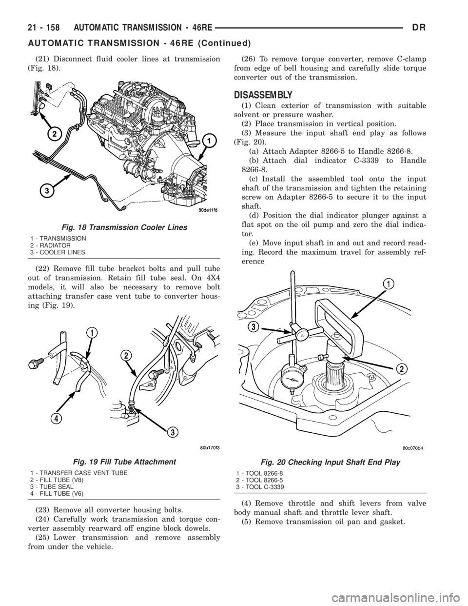
(21) Disconnect fluid cooler lines at transmission
(Fig. 18).
(22) Remove fill tube bracket bolts and pull tube
out of transmission. Retain fill tube seal. On 4X4
models, it will also be necessary to remove bolt
attaching transfer case vent tube to converter hous-
ing (Fig. 19).
(23) Remove all converter housing bolts.
(24) Carefully work transmission and torque con-
verter assembly rearward off engine block dowels.
(25) Lower transmission and remove assembly
from under the vehicle.(26) To remove torque converter, remove C-clamp
from edge of bell housing and carefully slide torque
converter out of the transmission.
DISASSEMBLY
(1) Clean exterior of transmission with suitable
solvent or pressure washer.
(2) Place transmission in vertical position.
(3) Measure the input shaft end play as follows
(Fig. 20).
(a) Attach Adapter 8266-5 to Handle 8266-8.
(b) Attach dial indicator C-3339 to Handle
8266-8.
(c) Install the assembled tool onto the input
shaft of the transmission and tighten the retaining
screw on Adapter 8266-5 to secure it to the input
shaft.
(d) Position the dial indicator plunger against a
flat spot on the oil pump and zero the dial indica-
tor.
(e) Move input shaft in and out and record read-
ing. Record the maximum travel for assembly ref-
erence
(4) Remove throttle and shift levers from valve
body manual shaft and throttle lever shaft.
(5) Remove transmission oil pan and gasket.
Fig. 18 Transmission Cooler Lines
1 - TRANSMISSION
2 - RADIATOR
3 - COOLER LINES
Fig. 19 Fill Tube Attachment
1 - TRANSFER CASE VENT TUBE
2 - FILL TUBE (V8)
3 - TUBE SEAL
4 - FILL TUBE (V6)
Fig. 20 Checking Input Shaft End Play
1 - TOOL 8266-8
2 - TOOL 8266-5
3 - TOOL C-3339
21 - 158 AUTOMATIC TRANSMISSION - 46REDR
AUTOMATIC TRANSMISSION - 46RE (Continued)
Page 2036 of 2895
Normal calibration will be performed when sump
temperature is above 50 degrees F, or in the absence
of sump temperature data, after the first 10 minutes
of vehicle operation. Calibration of the pressure
transducer offset occurs each time the output shaft
speed falls below 200 RPM. Calibration shall be
repeated each 3 seconds the output shaft speed is
below 200 RPM. A 0.5 second pulse of 95% duty cycle
is applied to the governor pressure solenoid valve
and the transducer output is read during this pulse.
Averaging of the transducer signal is necessary to
reject electrical noise.
Under cold conditions (below 50 degrees F sump),
the governor pressure solenoid valve response may
be too slow to guarantee 0 psi during the 0.5 second
calibration pulse. Calibration pulses are continued
during this period, however the transducer output
valves are discarded. Transducer offset must be read
at key-on, under conditions which promote a stable
reading. This value is retained and becomes the off-
set during the9cold9period of operation.
GOVERNOR PRESSURE SOLENOID VALVE
The inlet side of the solenoid valve is exposed to
normal transmission line pressure. The outlet side of
the valve leads to the valve body governor circuit.
The solenoid valve regulates line pressure to pro-
duce governor pressure. The average current sup-
plied to the solenoid controls governor pressure. One
amp current produces zero kPa/psi governor pres-
sure. Zero amps sets the maximum governor pres-
sure.
The powertrain control module (PCM) turns on the
trans control relay which supplies electrical power to
the solenoid valve. Operating voltage is 12 volts
(DC). The PCM controls the ground side of the sole-
noid using the governor pressure solenoid control cir-
cuit.
GOVERNOR PRESSURE SENSOR
The sensor output signal provides the necessary
feedback to the PCM. This feedback is needed to ade-
quately control governor pressure.
GOVERNOR BODY AND TRANSFER PLATE
The transfer plate channels line pressure to the
solenoid valve through the governor body. It also
channels governor pressure from the solenoid valve
to the governor circuit. It is the solenoid valve that
develops the necessary governor pressure.
GOVERNOR PRESSURE CURVES
LOW TRANSMISSION FLUID TEMPERATURE
When the transmission fluid is cold the conven-
tional governor can delay shifts, resulting in higherthan normal shift speeds and harsh shifts. The elec-
tronically controlled low temperature governor pres-
sure curve is higher than normal to make the
transmission shift at normal speeds and sooner. The
PCM uses a temperature sensor in the transmission
oil sump to determine when low temperature gover-
nor pressure is needed.
NORMAL OPERATION
Normal operation is refined through the increased
computing power of the PCM and through access to
data on engine operating conditions provided by the
PCM that were not available with the previous
stand-alone electronic module. This facilitated the
development of a load adaptive shift strategy - the
ability to alter the shift schedule in response to vehi-
cle load condition. One manifestation of this capabil-
ity is grade9hunting9prevention - the ability of the
transmission logic to delay an upshift on a grade if
the engine does not have sufficient power to main-
tain speed in the higher gear. The 3-2 downshift and
the potential for hunting between gears occurs with a
heavily loaded vehicle or on steep grades. When
hunting occurs, it is very objectionable because shifts
are frequent and accompanied by large changes in
noise and acceleration.
WIDE OPEN THROTTLE OPERATION
In wide-open throttle (WOT) mode, adaptive mem-
ory in the PCM assures that up-shifts occur at the
preprogrammed optimum speed. WOT operation is
determined from the throttle position sensor, which
is also a part of the emission control system. The ini-
tial setting for the WOT upshift is below the opti-
mum engine speed. As WOT shifts are repeated, the
PCM learns the time required to complete the shifts
by comparing the engine speed when the shifts occur
to the optimum speed. After each shift, the PCM
adjusts the shift point until the optimum speed is
reached. The PCM also considers vehicle loading,
grade and engine performance changes due to high
altitude in determining when to make WOT shifts. It
does this by measuring vehicle and engine accelera-
tion and then factoring in the shift time.
TRANSFER CASE LOW RANGE OPERATION
On four-wheel drive vehicles operating in low
range, the engine can accelerate to its peak more
rapidly than in Normal range, resulting in delayed
shifts and undesirable engine9flare.9The low range
governor pressure curve is also higher than normal
to initiate upshifts sooner. The PCM compares elec-
tronic vehicle speed signal used by the speedometer
to the transmission output shaft speed signal to
determine when the transfer case is in low range.
DRAUTOMATIC TRANSMISSION - 46RE 21 - 197
ELECTRONIC GOVERNOR (Continued)