2003 DODGE RAM ECO mode
[x] Cancel search: ECO modePage 2570 of 2895
WHEELS
DESCRIPTION
Original equipment wheels are designed for the
specified Maximum Vehicle Capacity.
All models use steel or aluminum drop center
wheels.
Aluminum wheels require special balance weights
and alignment equipment.
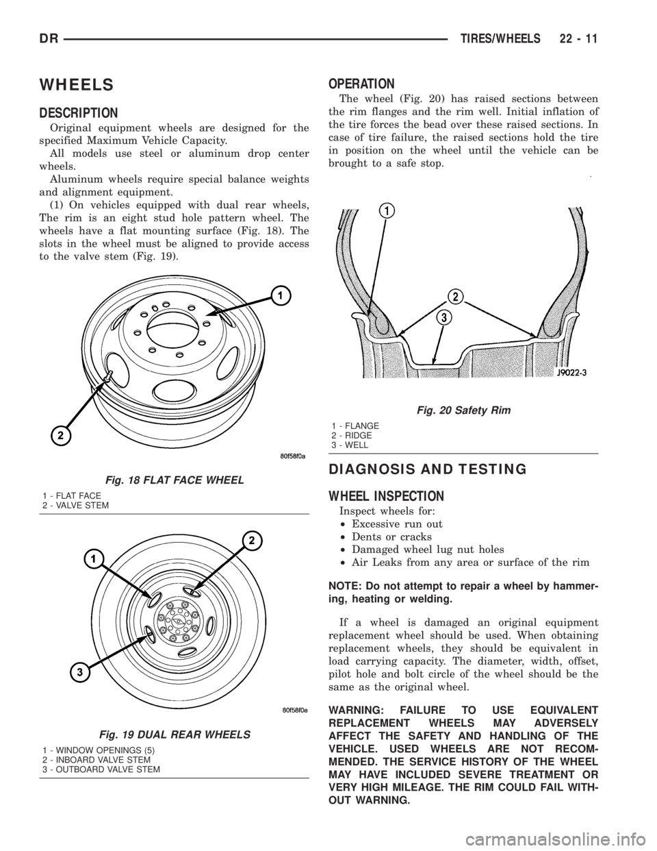
(1) On vehicles equipped with dual rear wheels,
The rim is an eight stud hole pattern wheel. The
wheels have a flat mounting surface (Fig. 18). The
slots in the wheel must be aligned to provide access
to the valve stem (Fig. 19).
OPERATION
The wheel (Fig. 20) has raised sections between
the rim flanges and the rim well. Initial inflation of
the tire forces the bead over these raised sections. In
case of tire failure, the raised sections hold the tire
in position on the wheel until the vehicle can be
brought to a safe stop.
DIAGNOSIS AND TESTING
WHEEL INSPECTION
Inspect wheels for:
²Excessive run out
²Dents or cracks
²Damaged wheel lug nut holes
²Air Leaks from any area or surface of the rim
NOTE: Do not attempt to repair a wheel by hammer-
ing, heating or welding.
If a wheel is damaged an original equipment
replacement wheel should be used. When obtaining
replacement wheels, they should be equivalent in
load carrying capacity. The diameter, width, offset,
pilot hole and bolt circle of the wheel should be the
same as the original wheel.
WARNING: FAILURE TO USE EQUIVALENT
REPLACEMENT WHEELS MAY ADVERSELY
AFFECT THE SAFETY AND HANDLING OF THE
VEHICLE. USED WHEELS ARE NOT RECOM-
MENDED. THE SERVICE HISTORY OF THE WHEEL
MAY HAVE INCLUDED SEVERE TREATMENT OR
VERY HIGH MILEAGE. THE RIM COULD FAIL WITH-
OUT WARNING.
Fig. 18 FLAT FACE WHEEL
1 - FLAT FACE
2 - VALVE STEM
Fig. 19 DUAL REAR WHEELS
1 - WINDOW OPENINGS (5)
2 - INBOARD VALVE STEM
3 - OUTBOARD VALVE STEM
Fig. 20 Safety Rim
1 - FLANGE
2 - RIDGE
3 - WELL
DRTIRES/WHEELS 22 - 11
Page 2649 of 2895
PAINT
TABLE OF CONTENTS
page page
PAINT
SPECIFICATIONS - PAINT CODES..........74
PAINT CODE
DESCRIPTION.........................74
BASECOAT/CLEARCOAT FINISH
DESCRIPTION.........................74PAINT TOUCH-UP
DESCRIPTION.........................75
STANDARD PROCEDURE - PAINT TOUCH-UP . 75
FINESSE SANDING/BUFFING & POLISHING
DESCRIPTION.........................75
PAINT
SPECIFICATIONS - PAINT CODES
NOTE: Because of late model changes to the avail-
able paint colors (Refer to VEHICLE DATA/VEHICLE
INFORMATION/VEHICLE SAFETY CERT LABEL -
DESCRIPTION) or (Refer to VEHICLE DATA/VEHI-
CLE INFORMATION/BODY CODE PLATE - DESCRIP-
TION) for the correct paint codes for each vehicle.
(Refer to 23 - BODY/PAINT/PAINT CODE - DESCRIP-
TION)
EXTERIOR COLORS
EXTERIOR COLOR DAIMLERCHRYSLER
CODE
Dark Garnet Red Pearl
CoatXRV
Flame Red Clear Coat PR4
Light Almond Pearl
Metallic Clear CoatZKJ
Atlantic Blue Pearl Coat ZBJ
Patriot Blue Pearl Coat WBT/WB7
Graphite Metallic Clear
CoatZDR
Bright Silver Metallic
Clear CoatWSB/WS2
Black Clear Coat DX8
Bright White Clear Coat GW7
Timberline Green AGW
INTERIOR COLORS
INTERIOR COLOR DAIMLERCHRYSLER
CODE
Taupe L5
Dark Slate Gray DV
PAINT CODE
DESCRIPTION
Exterior vehicle body colors are identified on the
Vehicle Safety Certification Label (Refer to VEHICLE
DATA/VEHICLE INFORMATION/VEHICLE
SAFETY CERTIFICATION LABEL - DESCRIP-
TION) or the Body Code Plate (Refer to VEHICLE
DATA/VEHICLE INFORMATION/BODY CODE
PLATE - DESCRIPTION). The first digit of the paint
code listed on the vehicle indicates the sequence of
application, i.e.: P = primary coat, Q = secondary
coat. The color names provided in the Paint and Trim
Code Description chart are the color names used on
most repair product containers. (Refer to 23 - BODY/
PAINT - SPECIFICATIONS)
BASECOAT/CLEARCOAT
FINISH
DESCRIPTION
The original equipment finish is a multi step pro-
cess that involves cleaning, applying electro de-posi-
tion (E-coat), anti-chip primer, basecoat, and
clearcoat steps.
On most vehicles a two-part paint application
(basecoat/clearcoat) is used. Color paint that is
applied to primer is called basecoat. The clearcoat
protects the basecoat from ultraviolet light and pro-
vides a durable high-gloss finish.
23 - 74 PAINTDR
Page 2776 of 2895
HEATING & AIR CONDITIONING
TABLE OF CONTENTS
page page
HEATING & AIR CONDITIONING
DESCRIPTION
DESCRIPTION - HEATER AND AIR
CONDITIONER........................1
DESCRIPTION - COOLING SYSTEM
REQUIREMENTS.......................1
DESCRIPTION - REFRIGERANT SYSTEM
SERVICE PORT........................1
OPERATION
OPERATION - HEATER AND AIR
CONDITIONER........................1
OPERATION - REFRIGERANT SYSTEM
SERVICE PORT........................2DIAGNOSIS AND TESTING
DIAGNOSIS AND TESTING - A/C
PERFORMANCE.......................2
DIAGNOSIS AND TESTING - HEATER
PERFORMANCE.......................5
STANDARD PROCEDURE - DIODE
REPLACEMENT.......................7
SPECIFICATIONS
A/C APPLICATION TABLE................7
SPECIFICATIONS......................8
CONTROLS.............................9
DISTRIBUTION..........................24
PLUMBING.............................31
HEATING & AIR
CONDITIONING
DESCRIPTION
DESCRIPTION - HEATER AND AIR
CONDITIONER
All vehicles are equipped with a common HVAC
housing assembly (Fig. 1). The system combines air
conditioning, heating, and ventilating capabilities in
a single unit housing mounted under the instrument
panel.
DESCRIPTION - COOLING SYSTEM
REQUIREMENTS
To maintain the performance level of the HVAC
system, the engine cooling system must be properly
maintained. The use of a bug screen is not recom-
mended. Any obstructions in front of the radiator or
condenser will reduce the performance of the air con-
ditioning and engine cooling systems.
The engine cooling system includes the heater core
and the heater hoses. Refer to Engine Cooling for
more information before the opening of, or attempt-
ing any service to the engine cooling system.
DESCRIPTION - REFRIGERANT SYSTEM
SERVICE PORT
The two refrigerant system service ports are used
to charge, recover/recycle, evacuate, and test the air
conditioning refrigerant system. Unique service port
coupler sizes are used on the R-134a system, toensure that the refrigerant system is not accidentally
contaminated by the use of the wrong refrigerant
(R-12), or refrigerant system service equipment.
OPERATION
OPERATION - HEATER AND AIR CONDITIONER
The heater air conditioner are blend-air type sys-
tems. In a blend-air system, a blend door controls the
amount of unconditioned air (or cooled air from the
evaporator on models with air conditioning) that is
allowed to flow through, or around, the heater core. A
temperature control knob on the A/C Heater control
panel determines the discharge air temperature by
controlling an electric actuator, which moves the
blend door. This allows an almost immediate control
of the output air temperature of the system.
The mode control knob on the A/C Heater control
panel is used to direct the conditioned air to the
selected system outlets. Both mode control switches
use electric actuators to control the mode doors.
On all vehicles, the outside air intake can be shut
off by selecting the Recirculation Mode with the
mode control knob. This will operate a electric actu-
ated recirculation door that closes off the outside
fresh air intake and recirculates the air that is
already inside the vehicle.
The air conditioner for all models is designed for
the use of non-CFC, R-134a refrigerant. The air con-
ditioning system has an evaporator to cool and dehu-
midify the incoming air prior to blending it with the
heated air. This air conditioning system uses a fixed
orifice tube in the liquid line near the condenser out-
let tube to meter refrigerant flow to the evaporator
DRHEATING & AIR CONDITIONING 24 - 1
Page 2780 of 2895
Pressure Diagnosis
Condition Possible Causes Correction
4. Air in the refrigerant
system.4. See Plumbing/Diagnosis and Testing -
Refrigerant System Leaks in this group. Test the
refrigerant system for leaks. Repair, evacuate and
charge the refrigerant system, if required.
5. Engine overheating. 5. Refer to Cooling for more information. Test the
cooling system and repair, if required.
The low side pressure is too
high, and the high side
pressure is too low.1. Accessory drive belt
slipping.1. Refer to Cooling for more information. Inspect
the accessory drive belt condition and tension.
Tighten or replace the accessory drive belt, if
required.
2. Fixed orifice tube not
installed.2. See A/C Orifice Tube in this group. Replace
the liquid line, if required.
3. Faulty compressor. 3. See A/C Compressor in this group. Replace
the compressor, if required.
The low side pressure is too
low, and the high side
pressure is too high.1. Restricted refrigerant flow
through the refrigerant lines.1. See Liquid, Suction, and Discharge Line in this
group. Inspect the refrigerant lines for kinks, tight
bends or improper routing. Correct the routing or
replace the refrigerant line, if required.
2. Restricted refrigerant flow
through the fixed orifice tube.2. See A/C Orifice Tube in this group. Replace
the liquid line, if required.
3. Restricted refrigerant flow
through the condenser.3. See A/C Condenser in this group. Replace the
restricted condenser, if required.
DIAGNOSIS AND TESTING - HEATER
PERFORMANCE
Before performing the following tests, refer to Cool-
ing for the procedures to check the engine coolant
level and flow, engine coolant reserve/recovery sys-
tem operation, accessory drive belt condition and ten-
sion, radiator air flow and the fan drive operation.
Also be certain that the accessory vacuum supply
line is connected at the engine vacuum source.
MAXIMUM HEATER OUTPUT
Engine coolant is delivered to the heater core
through two heater hoses. With the engine idling at
normal operating temperature, set the temperature
control knob in the full hot position, the mode control
switch knob in the floor position, and the blower
motor switch knob in the highest speed position.
Using a test thermometer, check the temperature of
the air being discharged at the HVAC housing floor
outlets. Compare the test thermometer reading to the
Temperature Reference chart.
Temperature Reference
Ambient Air Temperature15.5É C
(60É F)21.1É C
(70É F)26.6É C
(80É F)32.2É C
(90É F)
Minimum Air Temperature at
Floor Outlet62.2É C
(144É F)63.8É C
(147É F)65.5É C
(150É F)67.2É C
(153É F)
DRHEATING & AIR CONDITIONING 24 - 5
HEATING & AIR CONDITIONING (Continued)
Page 2785 of 2895
seconds. Refer to Electronic Control Modules for
more information on the JTEC controls.
DIAGNOSIS AND TESTING - A/C COMPRESSOR
CLUTCH COIL
For circuit descriptions and diagrams, (Refer to
Appropriate Wiring Information). The battery must
be fully-charged before performing the following
tests. Refer to Battery for more information.
(1) Connect an ammeter (0 to 10 ampere scale) in
series with the clutch coil terminal. Use a voltmeter
(0 to 20 volt scale) with clip-type leads for measuring
the voltage across the battery and the compressor
clutch coil.
(2) With the A/C Heater mode control switch in
any A/C mode, and the blower motor switch in the
lowest speed position, start the engine and run it at
normal idle.
(3) The compressor clutch coil voltage should read
within 0.2 volts of the battery voltage. If there is
voltage at the clutch coil, but the reading is not
within 0.2 volts of the battery voltage, test the clutch
coil feed circuit for excessive voltage drop and repair
as required. If there is no voltage reading at the
clutch coil, use a DRB IIItscan tool and (Refer to
Appropriate Diagnostic Information) for testing of the
compressor clutch circuit and PCM control. The fol-
lowing components must be checked and repaired as
required before you can complete testing of the clutch
coil:
²Fuses in the junction block and the Power Dis-
tribution Center (PDC)
²A/C heater mode control switch
²Compressor clutch relay
²A/C high pressure transducer switch²JTEC
(4) The compressor clutch coil is acceptable if the
current draw measured at the clutch coil is 2.0 to 3.9
amperes with the electrical system voltage at 11.5 to
12.5 volts. This should only be checked with the work
area temperature at 21É C (70É F). If system voltage
is more than 12.5 volts, add electrical loads by turn-
ing on electrical accessories until the system voltage
drops below 12.5 volts.
(a) If the clutch coil current reading is four
amperes or more, the coil is shorted and should be
replaced.
(b) If the clutch coil current reading is zero, the
coil is open and should be replaced.
STANDARD PROCEDURE - A/C COMPRESSOR
CLUTCH BREAK-IN
After a new compressor clutch has been installed,
cycle the compressor clutch approximately twenty
times (five seconds on, then five seconds off). During
this procedure, set the A/C Heater control to the
Recirculation Mode, the blower motor switch in the
highest speed position, and the engine speed at 1500
to 2000 rpm. This procedure (burnishing) will seat
the opposing friction surfaces and provide a higher
compressor clutch torque capability.
REMOVAL
The refrigerant system can remain fully-charged
during compressor clutch, rotor, or coil replacement.
The compressor clutch can be serviced in the vehicle.
(1) Disconnect and isolate the battery negative
cable.
(2) Remove the serpentine drive belt(Refer to 7 -
COOLING/ACCESSORY DRIVE/DRIVE BELTS -
REMOVAL).
(3) Unplug the compressor clutch coil wire harness
connector.
(4) Remove the bolts that secure the compressor to
the mounting bracket.
(5) Remove the compressor from the mounting
bracket. Support the compressor in the engine com-
partment while servicing the clutch.
(6) Insert the two pins of the spanner wrench
(Special Tool C-4489 or equivalent) into the holes of
the clutch plate. Hold the clutch plate stationary and
remove the hex nut (Fig. 2).
(7) Remove the clutch plate.
(8) Remove the compressor clutch shims.
(9) Remove the external front housing snap ring
with snap ring pliers (Fig. 3).
(10)
Install the lip of the rotor puller (Special Tool
C-6141-1 or equivalent) into the snap ring groove
exposed in the previous step, and install the shaft pro-
tector (Special Tool C-6141-2 or equivalent) (Fig. 4).
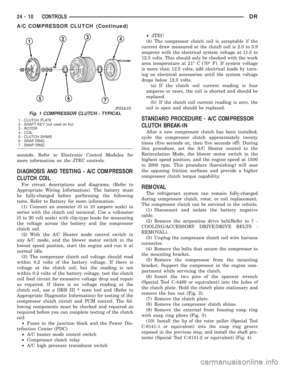
Fig. 1 COMPRESSOR CLUTCH - TYPICAL
1 - CLUTCH PLATE
2 - SHAFT KEY (not used on KJ)
3 - ROTOR
4 - COIL
5 - CLUTCH SHIMS
6 - SNAP RING
7 - SNAP RING
24 - 10 CONTROLSDR
A/C COMPRESSOR CLUTCH (Continued)
Page 2791 of 2895
an A/C pressure transducer voltage reading between
0.451 and 4.519 volts is required. Voltages outside
this range indicate a low or high refrigerant system
pressure condition to the Powertrain Control Module
(PCM). The PCM is programmed to respond to a low
or high refrigerant system pressure by suppressing
operation of the compressor. Refer to the A/C Pres-
sure Transducer Voltage table for the possible condi-
tion indicated by the transducer voltage readings.
A/C PRESSURE TRANSDUCER VOLTAGE
VOLTAGE POSSIBLE INDICATION
0.0 1. NO SENSOR SUPPLY
VOLTAGE FROM PCM.
2. SHORTED SENSOR CIRCUIT.
3. FAULTY TRANSDUCER.
0.150 TO 0.450 1. AMBIENT TEMPERATURE
BELOW 10É C (50É F).
2. LOW REFRIGERANT
SYSTEM PRESSURE.
0.451 TO 4.519 1. NORMAL REFRIGERANT
SYSTEM PRESSURE.
4.520 TO 4.850 1. HIGH REFRIGERANT
SYSTEM PRESSURE.
5.0 1. OPEN SENSOR CIRCUIT.
2. FAULTY TRANSDUCER.
REMOVAL
(1) Disconnect and isolate the battery negative
cable.
(2) Disconnect the wire harness connector for the
A/C pressure transducer from the transducer connec-
tor receptacle.
(3) Using an open end wrench, unscrew the A/C
pressure transducer from the fitting on the discharge
line between the compressor and the condenser.
(4) Remove the seal from the A/C pressure trans-
ducer fitting and discard.
INSTALLATION
(1) Lubricate a new rubber O-ring seal with clean
refrigerant oil and install it on the A/C pressure
transducer fitting.
(2) Using an open end wrench, install and tighten
the A/C pressure transducer onto the fitting on the
discharge line between the compressor and the con-
denser.
(3) Reconnect the wire harness connector for the
A/C pressure transducer to the transducer connector
receptacle.
(4) Reconnect the battery negative cable.
BLEND DOOR ACTUATOR
DESCRIPTION
The blend door actuators are reversible, 12-volt
Direct Current (DC), servo motors. Models with the
single zone heater and air conditioner system have a
single blend air door, which is controlled by a single
blend door actuator. Models with the optional dual
zone front heater and air conditioner system have
dual blend air doors, which are controlled by two
blend door actuators. The single zone blend door
actuator is located on the driver side end of the heat-
er-A/C housing unit, close to the dash panel. In the
dual zone system, the same blend door actuator used
for the single zone system becomes the driver side
blend door actuator, and is mechanically connected to
only the driver side blend air door. In the dual zone
system, a second separate blend door actuator is also
located on the top of the heater-A/C housing unit and
is mechanically connected to only the passenger side
blend air door.
The blend door actuators are interchangeable with
each other, as well as with the actuators for the
mode door and the recirculation air door. Each actua-
tor is contained within an identical black molded
plastic housing with an integral wire connector
receptacle. Two integral mounting tabs allow the
actuator to be secured with two screws to the heater-
A/C unit housing. Each actuator also has an identical
output shaft with splines that connects it to the link-
age that drives the proper blend air door. The blend
door actuators do not require mechanical indexing to
the blend door linkage, as they are electronically cal-
ibrated by the heater-A/C control module. The blend
door actuators cannot be adjusted or repaired and, if
damaged or faulty, they must be replaced.
OPERATION
Each blend door actuator is connected to the heat-
er-A/C control module through the vehicle electrical
system by a dedicated two-wire take out and connec-
tor of the HVAC wire harness. The blend door actua-
tor can move the blend air door in two directions.
When the heater-A/C control module pulls the volt-
age on one side of the motor connection high and the
other connection low, the blend air door will move in
one direction. When the module reverses the polarity
of the voltage to the motor, the blend air door moves
in the opposite direction. When the module makes
the voltage to both connections high or both connec-
tions low, the blend air door stops and will not move.
These same motor connections also provide a feed-
back signal to the heater-A/C control module. This
feedback signal allows the module to monitor the
operation and relative positions of the blend door
actuator and the blend air door. The heater-A/C con-
24 - 16 CONTROLSDR
A/C PRESSURE TRANSDUCER (Continued)
Page 2796 of 2895
to the mode door linkage, as it is electronically cali-
brated by the heater-A/C control module. The mode
door actuator cannot be adjusted or repaired and, if
damaged or faulty, it must be replaced.
OPERATION
The mode door actuator is connected to the heater-
A/C control module through the vehicle electrical sys-
tem by a dedicated two-wire take out and connector
of the HVAC wire harness. The mode door actuator
can move the mode door in two directions. When the
heater-A/C control module pulls the voltage on one
side of the motor connection high and the other con-
nection low, the mode door will move in one direction.
When the module reverses the polarity of the voltage
to the motor, the mode door moves in the opposite
direction. When the module makes the voltage to
both connections high or both connections low, the
mode door stops and will not move. These same
motor connections also provide a feedback signal to
the heater-A/C control module. This feedback signal
allows the module to monitor the operation and rela-
tive position of the mode door actuator and the mode
door. The heater-A/C control module learns the mode
door stop positions during the calibration procedure
and will store a Diagnostic Trouble Code (DTC) for
any problems it detects in the mode door actuator
circuits. The mode door actuator can be diagnosed
using a DRBIIItscan tool. Refer to the appropriate
diagnostic information.
REMOVAL
WARNING: ON VEHICLES EQUIPPED WITH AIR-
BAGS, DISABLE THE AIRBAG SYSTEM BEFORE
ATTEMPTING ANY STEERING WHEEL, STEERING
COLUMN, OR INSTRUMENT PANEL COMPONENT
DIAGNOSIS OR SERVICE. DISCONNECT AND ISO-
LATE THE BATTERY NEGATIVE (GROUND) CABLE,
THEN WAIT TWO MINUTES FOR THE AIRBAG SYS-
TEM CAPACITOR TO DISCHARGE BEFORE PER-
FORMING FURTHER DIAGNOSIS OR SERVICE. THIS
IS THE ONLY SURE WAY TO DISABLE THE AIRBAG
SYSTEM. FAILURE TO TAKE THE PROPER PRE-
CAUTIONS COULD RESULT IN ACCIDENTAL AIR-
BAG DEPLOYMENT AND POSSIBLE PERSONAL
INJURY.
(1) Disconnect and isolate the battery negative
cable.
(2) Remove the instrument panel assembly(Refer
to 23 - BODY/INSTRUMENT PANEL/INSTRUMENT
PANEL ASSEMBLY - REMOVAL).
(3) Disconnect the electricial connector from the
actuator (single or dual zone as required).
(4) Remove the two screws that secure the mode
door actuators to the distribution housing. For singlezone systems only lower actuator in present. For dual
zone systems remove second actuator which is
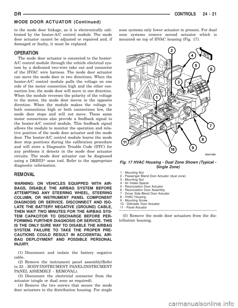
mounted on top of HVAC housing (Fig. 17).
(5) Remove the mode door actuators from the dis-
tribution housing.
Fig. 17 HVAC Housing - Dual Zone Shown (Typical -
Single Zone)
1 - Mounting Nut
2 - Passenger Blend Door Actuator (dual zone)
3 - Mounting Nut
4 - Air Intake Spacer
5 - Recirculation Door Actuator
6 - Recirculation Door Assembly
7 - Driver Side Blend Door Actuator
8 - HVAC Housing
9 - Mounting Screw
10 - Defroster Door Actuator
11 - Panel Actuator
DRCONTROLS 24 - 21
MODE DOOR ACTUATOR (Continued)
Page 2797 of 2895
INSTALLATION
WARNING: ON VEHICLES EQUIPPED WITH AIR-
BAGS, DISABLE THE AIRBAG SYSTEM BEFORE
ATTEMPTING ANY STEERING WHEEL, STEERING
COLUMN, OR INSTRUMENT PANEL COMPONENT
DIAGNOSIS OR SERVICE. DISCONNECT AND ISO-
LATE THE BATTERY NEGATIVE (GROUND) CABLE,
THEN WAIT TWO MINUTES FOR THE AIRBAG SYS-
TEM CAPACITOR TO DISCHARGE BEFORE PER-
FORMING FURTHER DIAGNOSIS OR SERVICE. THIS
IS THE ONLY SURE WAY TO DISABLE THE AIRBAG
SYSTEM. FAILURE TO TAKE THE PROPER PRE-
CAUTIONS COULD RESULT IN ACCIDENTAL AIR-
BAG DEPLOYMENT AND POSSIBLE PERSONAL
INJURY.
(1) Position the mode door actuators onto the heat-
er/AC housing. If necessary, rotate the actuator
slightly to align the splines on the actuator output
shaft with those in the mode door linkage.
(2) Install and tighten the two screws that secure
the mode door actuators to the distribution housing.
Tighten the screws to 2 N´m (17 in. lbs.).
(3) Reconnect the HVAC wire harness connector
for the mode door actuators to the actuator connector
receptacle.
(4) Install the instrument panel assembly(Refer to
23 - BODY/INSTRUMENT PANEL/INSTRUMENT
PANEL ASSEMBLY - INSTALLATION).
(5) Reconnect the battery negative cable.
(6) Perform the heater-A/C control calibration pro-
cedure. (Refer to 24 - HEATING & AIR CONDITION-
ING/CONTROLS - FRONT/A/C-HEATER CONTROL
- STANDARD PROCEDURE - HEATER-A/C CON-
TROL CALIBRATION).
RECIRCULATION DOOR
ACTUATOR
DESCRIPTION
The recirculation door actuator is a reversible,
12-volt Direct Current (DC), servo motor. The single
recirculation door actuator is located on the passen-
ger side end of the heater-A/C housing unit. The
recirculation door actuator is mechanically connected
to the recirculation air door. The recirculation door
actuator is interchangeable with the actuators for the
blend air door(s) and the mode doors. Each actuator
is contained within an identical black molded plastic
housing with an integral wire connector receptacle.
Two integral mounting tabs allow the actuator to be
secured with two screws to the intake air housing.
Each actuator also has an identical output shaft with
splines that connects it to the linkage that drives therecirculation air door. The recirculation door actuator
does not require mechanical indexing to the recircu-
lation air door, as it is electronically calibrated by the
heater-A/C control module. The recirculation door
actuator cannot be adjusted or repaired and, if dam-
aged or faulty, it must be replaced.
OPERATION
The recirculation door actuator is connected to the
heater-A/C control module through the vehicle elec-
trical system by a dedicated two-wire take out and
connector of the HVAC wire harness. The recircula-
tion door actuator can move the recirculation door in
two directions. When the heater-A/C control module
pulls the voltage on one side of the motor connection
high and the other connection low, the recirculation
air door will move in one direction. When the module
reverses the polarity of the voltage to the motor, the
recirculation air door moves in the opposite direction.
When the module makes the voltage to both connec-
tions high or both connections low, the recirculation
air door stops and will not move. These same motor
connections also provide a feedback signal to the
heater-A/C control module. This feedback signal
allows the module to monitor the operation and rela-
tive position of the recirculation door actuator and
the recirculation air door. The heater-A/C control
module learns the recirculation air door stop posi-
tions during the calibration procedure and will store
a Diagnostic Trouble Code (DTC) for any problems it
detects in the recirculation door actuator circuits.
The recirculation door actuator can be diagnosed
using a DRBIIItscan tool. Refer to the appropriate
diagnostic information.
REMOVAL
WARNING: ON VEHICLES EQUIPPED WITH AIR-
BAGS, DISABLE THE AIRBAG SYSTEM BEFORE
ATTEMPTING ANY STEERING WHEEL, STEERING
COLUMN, OR INSTRUMENT PANEL COMPONENT
DIAGNOSIS OR SERVICE. DISCONNECT AND ISO-
LATE THE BATTERY NEGATIVE (GROUND) CABLE,
THEN WAIT TWO MINUTES FOR THE AIRBAG SYS-
TEM CAPACITOR TO DISCHARGE BEFORE PER-
FORMING FURTHER DIAGNOSIS OR SERVICE. THIS
IS THE ONLY SURE WAY TO DISABLE THE AIRBAG
SYSTEM. FAILURE TO TAKE THE PROPER PRE-
CAUTIONS COULD RESULT IN ACCIDENTAL AIR-
BAG DEPLOYMENT AND POSSIBLE PERSONAL
INJURY.
(1) Disconnect and isolate the battery negative
cable.
(2) Pull the carpet on the passenger side front
floor away from the dash panel far enough to access
the recirculation door actuator.
24 - 22 CONTROLSDR
MODE DOOR ACTUATOR (Continued)