2003 DODGE RAM ECO mode
[x] Cancel search: ECO modePage 2451 of 2895
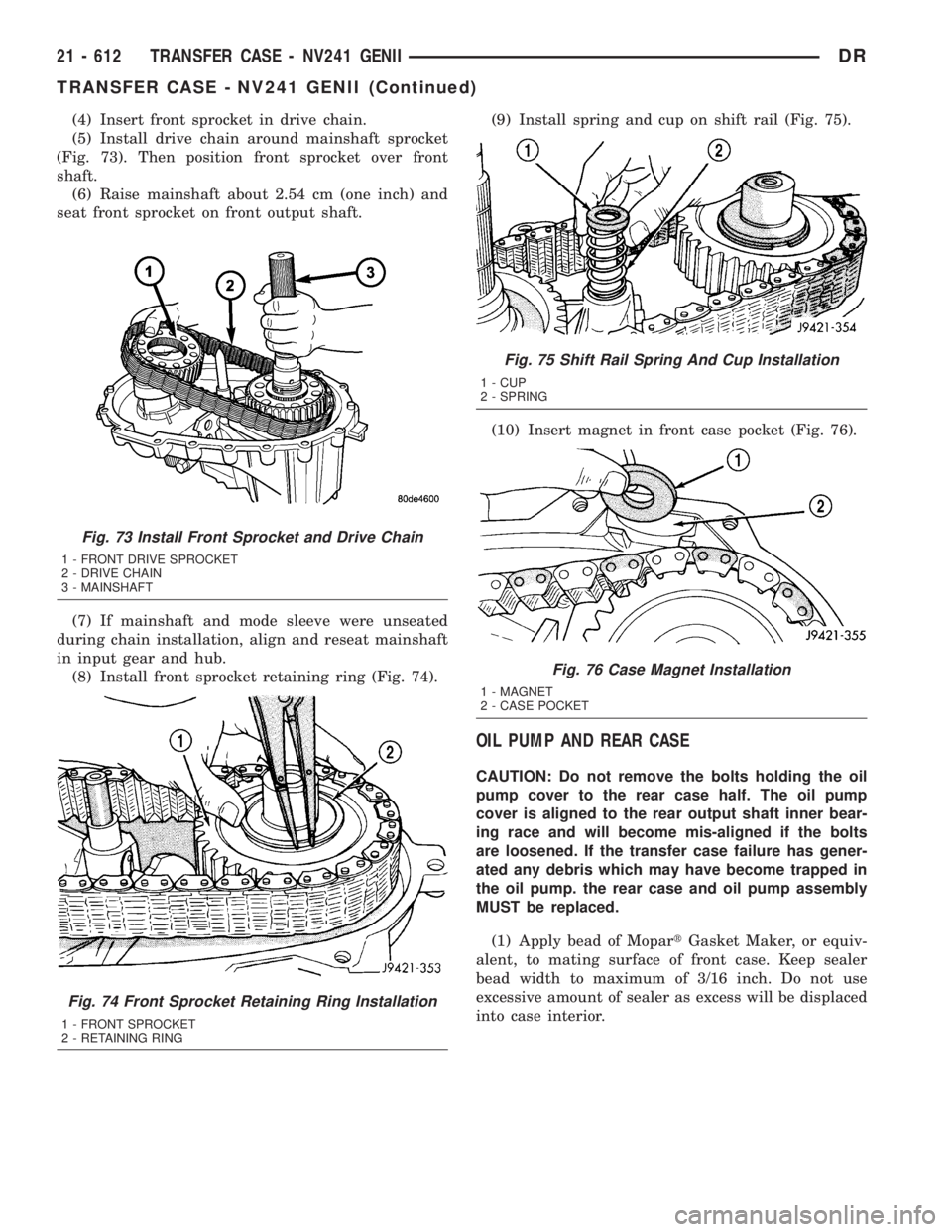
(4) Insert front sprocket in drive chain.
(5) Install drive chain around mainshaft sprocket
(Fig. 73). Then position front sprocket over front
shaft.
(6) Raise mainshaft about 2.54 cm (one inch) and
seat front sprocket on front output shaft.
(7) If mainshaft and mode sleeve were unseated
during chain installation, align and reseat mainshaft
in input gear and hub.
(8) Install front sprocket retaining ring (Fig. 74).(9) Install spring and cup on shift rail (Fig. 75).
(10) Insert magnet in front case pocket (Fig. 76).
OIL PUMP AND REAR CASE
CAUTION: Do not remove the bolts holding the oil
pump cover to the rear case half. The oil pump
cover is aligned to the rear output shaft inner bear-
ing race and will become mis-aligned if the bolts
are loosened. If the transfer case failure has gener-
ated any debris which may have become trapped in
the oil pump. the rear case and oil pump assembly
MUST be replaced.
(1) Apply bead of MopartGasket Maker, or equiv-
alent, to mating surface of front case. Keep sealer
bead width to maximum of 3/16 inch. Do not use
excessive amount of sealer as excess will be displaced
into case interior.
Fig. 73 Install Front Sprocket and Drive Chain
1 - FRONT DRIVE SPROCKET
2 - DRIVE CHAIN
3 - MAINSHAFT
Fig. 74 Front Sprocket Retaining Ring Installation
1 - FRONT SPROCKET
2 - RETAINING RING
Fig. 75 Shift Rail Spring And Cup Installation
1 - CUP
2 - SPRING
Fig. 76 Case Magnet Installation
1 - MAGNET
2 - CASE POCKET
21 - 612 TRANSFER CASE - NV241 GENIIDR
TRANSFER CASE - NV241 GENII (Continued)
Page 2481 of 2895
SHIFT FORKS AND MAINSHAFT
(1) Lubricate mainshaft splines with recommended
transmission fluid.
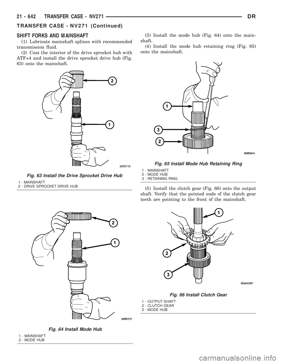
(2) Coat the interior of the drive sprocket hub with
ATF+4 and install the drive sprocket drive hub (Fig.
63) onto the mainshaft.(3) Install the mode hub (Fig. 64) onto the main-
shaft.
(4) Install the mode hub retaining ring (Fig. 65)
onto the mainshaft.
(5) Install the clutch gear (Fig. 66) onto the output
shaft. Verify that the pointed ends of the clutch gear
teeth are pointing to the front of the mainshaft.
Fig. 64 Install Mode Hub
1 - MAINSHAFT
2 - MODE HUB
Fig. 63 Install the Drive Sprocket Drive Hub
1 - MAINSHAFT
2 - DRIVE SPROCKET DRIVE HUB
Fig. 65 Install Mode Hub Retaining Ring
1 - MAINSHAFT
2 - MODE HUB
3 - RETAINING RING
Fig. 66 Install Clutch Gear
1 - OUTPUT SHAFT
2 - CLUTCH GEAR
3 - MODE HUB
21 - 642 TRANSFER CASE - NV271DR
TRANSFER CASE - NV271 (Continued)
Page 2513 of 2895
SHIFT FORKS AND MAINSHAFT
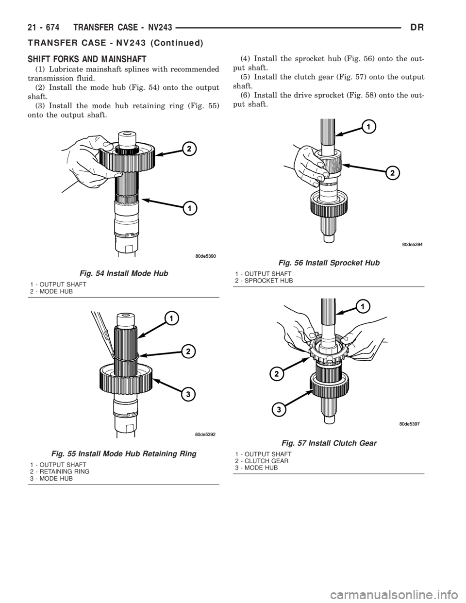
(1) Lubricate mainshaft splines with recommended
transmission fluid.
(2) Install the mode hub (Fig. 54) onto the output
shaft.
(3) Install the mode hub retaining ring (Fig. 55)
onto the output shaft.(4) Install the sprocket hub (Fig. 56) onto the out-
put shaft.
(5) Install the clutch gear (Fig. 57) onto the output
shaft.
(6) Install the drive sprocket (Fig. 58) onto the out-
put shaft.
Fig. 54 Install Mode Hub
1 - OUTPUT SHAFT
2 - MODE HUB
Fig. 55 Install Mode Hub Retaining Ring
1 - OUTPUT SHAFT
2 - RETAINING RING
3 - MODE HUB
Fig. 56 Install Sprocket Hub
1 - OUTPUT SHAFT
2 - SPROCKET HUB
Fig. 57 Install Clutch Gear
1 - OUTPUT SHAFT
2 - CLUTCH GEAR
3 - MODE HUB
21 - 674 TRANSFER CASE - NV243DR
TRANSFER CASE - NV243 (Continued)
Page 2517 of 2895
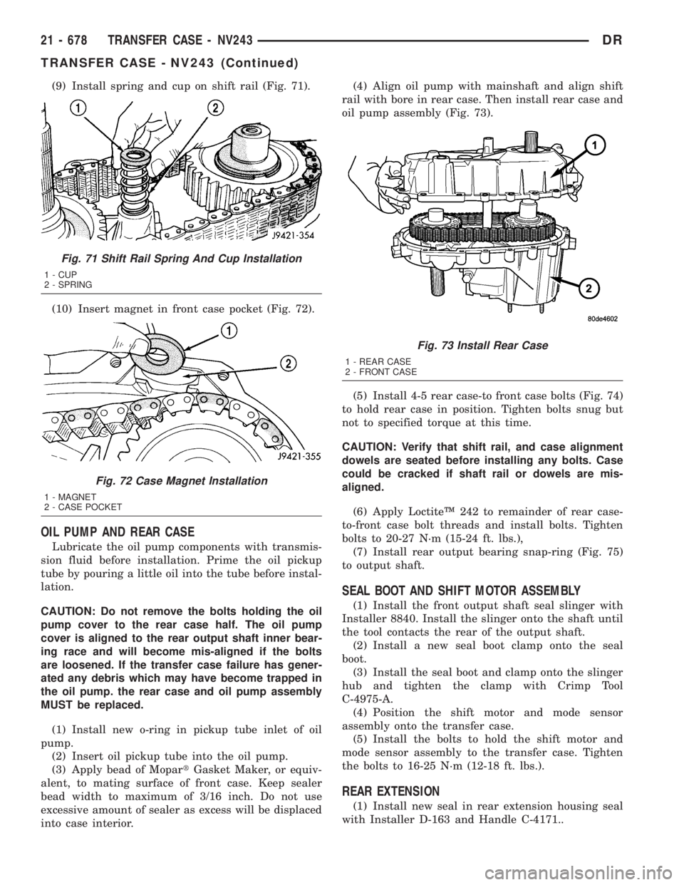
(9) Install spring and cup on shift rail (Fig. 71).
(10) Insert magnet in front case pocket (Fig. 72).
OIL PUMP AND REAR CASE
Lubricate the oil pump components with transmis-
sion fluid before installation. Prime the oil pickup
tube by pouring a little oil into the tube before instal-
lation.
CAUTION: Do not remove the bolts holding the oil
pump cover to the rear case half. The oil pump
cover is aligned to the rear output shaft inner bear-
ing race and will become mis-aligned if the bolts
are loosened. If the transfer case failure has gener-
ated any debris which may have become trapped in
the oil pump. the rear case and oil pump assembly
MUST be replaced.
(1) Install new o-ring in pickup tube inlet of oil
pump.
(2) Insert oil pickup tube into the oil pump.
(3) Apply bead of MopartGasket Maker, or equiv-
alent, to mating surface of front case. Keep sealer
bead width to maximum of 3/16 inch. Do not use
excessive amount of sealer as excess will be displaced
into case interior.(4) Align oil pump with mainshaft and align shift
rail with bore in rear case. Then install rear case and
oil pump assembly (Fig. 73).
(5) Install 4-5 rear case-to front case bolts (Fig. 74)
to hold rear case in position. Tighten bolts snug but
not to specified torque at this time.
CAUTION: Verify that shift rail, and case alignment
dowels are seated before installing any bolts. Case
could be cracked if shaft rail or dowels are mis-
aligned.
(6) Apply LoctiteŸ 242 to remainder of rear case-
to-front case bolt threads and install bolts. Tighten
bolts to 20-27 N´m (15-24 ft. lbs.),
(7) Install rear output bearing snap-ring (Fig. 75)
to output shaft.
SEAL BOOT AND SHIFT MOTOR ASSEMBLY
(1) Install the front output shaft seal slinger with
Installer 8840. Install the slinger onto the shaft until
the tool contacts the rear of the output shaft.
(2) Install a new seal boot clamp onto the seal
boot.
(3) Install the seal boot and clamp onto the slinger
hub and tighten the clamp with Crimp Tool
C-4975-A.
(4) Position the shift motor and mode sensor
assembly onto the transfer case.
(5) Install the bolts to hold the shift motor and
mode sensor assembly to the transfer case. Tighten
the bolts to 16-25 N´m (12-18 ft. lbs.).
REAR EXTENSION
(1) Install new seal in rear extension housing seal
with Installer D-163 and Handle C-4171..
Fig. 71 Shift Rail Spring And Cup Installation
1 - CUP
2 - SPRING
Fig. 72 Case Magnet Installation
1 - MAGNET
2 - CASE POCKET
Fig. 73 Install Rear Case
1 - REAR CASE
2 - FRONT CASE
21 - 678 TRANSFER CASE - NV243DR
TRANSFER CASE - NV243 (Continued)
Page 2523 of 2895
MODE SENSOR
DESCRIPTION
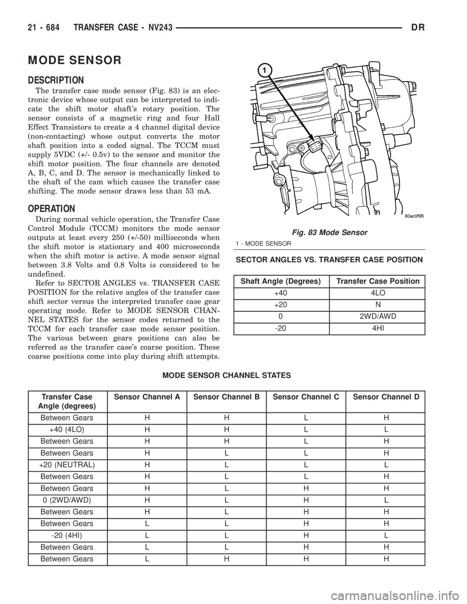
The transfer case mode sensor (Fig. 83) is an elec-
tronic device whose output can be interpreted to indi-
cate the shift motor shaft's rotary position. The
sensor consists of a magnetic ring and four Hall
Effect Transistors to create a 4 channel digital device
(non-contacting) whose output converts the motor
shaft position into a coded signal. The TCCM must
supply 5VDC (+/- 0.5v) to the sensor and monitor the
shift motor position. The four channels are denoted
A, B, C, and D. The sensor is mechanically linked to
the shaft of the cam which causes the transfer case
shifting. The mode sensor draws less than 53 mA.
OPERATION
During normal vehicle operation, the Transfer Case
Control Module (TCCM) monitors the mode sensor
outputs at least every 250 (+/-50) milliseconds when
the shift motor is stationary and 400 microseconds
when the shift motor is active. A mode sensor signal
between 3.8 Volts and 0.8 Volts is considered to be
undefined.
Refer to SECTOR ANGLES vs. TRANSFER CASE
POSITION for the relative angles of the transfer case
shift sector versus the interpreted transfer case gear
operating mode. Refer to MODE SENSOR CHAN-
NEL STATES for the sensor codes returned to the
TCCM for each transfer case mode sensor position.
The various between gears positions can also be
referred as the transfer case's coarse position. These
coarse positions come into play during shift attempts.SECTOR ANGLES VS. TRANSFER CASE POSITION
Shaft Angle (Degrees) Transfer Case Position
+40 4LO
+20 N
0 2WD/AWD
-20 4HI
MODE SENSOR CHANNEL STATES
Transfer Case
Angle (degrees)Sensor Channel A Sensor Channel B Sensor Channel C Sensor Channel D
Between Gears H H L H
+40 (4LO) H H L L
Between Gears H H L H
Between Gears H L L H
+20 (NEUTRAL) H L L L
Between Gears H L L H
Between Gears H L H H
0 (2WD/AWD) H L H L
Between Gears H L H H
Between Gears L L H H
-20 (4HI) L L H L
Between Gears L L H H
Between Gears L H H H
Fig. 83 Mode Sensor
1 - MODE SENSOR
21 - 684 TRANSFER CASE - NV243DR
Page 2545 of 2895
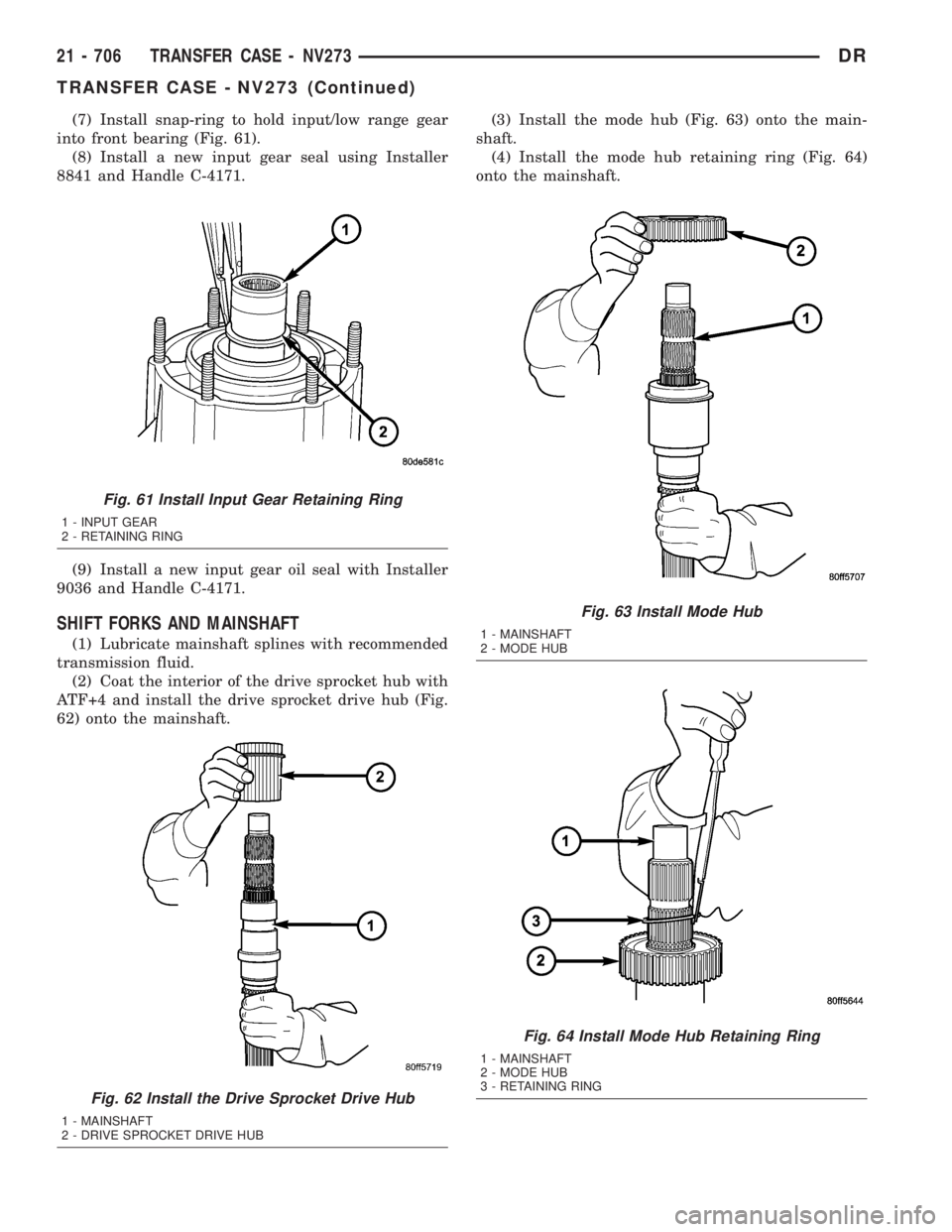
(7) Install snap-ring to hold input/low range gear
into front bearing (Fig. 61).
(8) Install a new input gear seal using Installer
8841 and Handle C-4171.
(9) Install a new input gear oil seal with Installer
9036 and Handle C-4171.
SHIFT FORKS AND MAINSHAFT
(1) Lubricate mainshaft splines with recommended
transmission fluid.
(2) Coat the interior of the drive sprocket hub with
ATF+4 and install the drive sprocket drive hub (Fig.
62) onto the mainshaft.(3) Install the mode hub (Fig. 63) onto the main-
shaft.
(4) Install the mode hub retaining ring (Fig. 64)
onto the mainshaft.
Fig. 61 Install Input Gear Retaining Ring
1 - INPUT GEAR
2 - RETAINING RING
Fig. 62 Install the Drive Sprocket Drive Hub
1 - MAINSHAFT
2 - DRIVE SPROCKET DRIVE HUB
Fig. 63 Install Mode Hub
1 - MAINSHAFT
2 - MODE HUB
Fig. 64 Install Mode Hub Retaining Ring
1 - MAINSHAFT
2 - MODE HUB
3 - RETAINING RING
21 - 706 TRANSFER CASE - NV273DR
TRANSFER CASE - NV273 (Continued)
Page 2557 of 2895
MODE SENSOR
DESCRIPTION
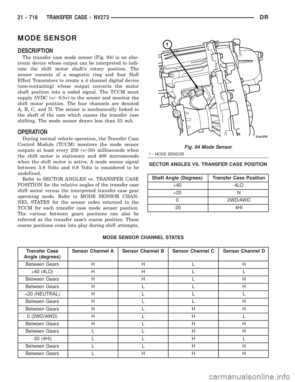
The transfer case mode sensor (Fig. 94) is an elec-
tronic device whose output can be interpreted to indi-
cate the shift motor shaft's rotary position. The
sensor consists of a magnetic ring and four Hall
Effect Transistors to create a 4 channel digital device
(non-contacting) whose output converts the motor
shaft position into a coded signal. The TCCM must
supply 5VDC (+/- 0.5v) to the sensor and monitor the
shift motor position. The four channels are denoted
A, B, C, and D. The sensor is mechanically linked to
the shaft of the cam which causes the transfer case
shifting. The mode sensor draws less than 53 mA.
OPERATION
During normal vehicle operation, the Transfer Case
Control Module (TCCM) monitors the mode sensor
outputs at least every 250 (+/-50) milliseconds when
the shift motor is stationary and 400 microseconds
when the shift motor is active. A mode sensor signal
between 3.8 Volts and 0.8 Volts is considered to be
undefined.
Refer to SECTOR ANGLES vs. TRANSFER CASE
POSITION for the relative angles of the transfer case
shift sector versus the interpreted transfer case gear
operating mode. Refer to MODE SENSOR CHAN-
NEL STATES for the sensor codes returned to the
TCCM for each transfer case mode sensor position.
The various between gears positions can also be
referred as the transfer case's coarse position. These
coarse positions come into play during shift attempts.SECTOR ANGLES VS. TRANSFER CASE POSITION
Shaft Angle (Degrees) Transfer Case Position
+40 4LO
+20 N
0 2WD/AWD
-20 4HI
MODE SENSOR CHANNEL STATES
Transfer Case
Angle (degrees)Sensor Channel A Sensor Channel B Sensor Channel C Sensor Channel D
Between Gears H H L H
+40 (4LO) H H L L
Between Gears H H L H
Between Gears H L L H
+20 (NEUTRAL) H L L L
Between Gears H L L H
Between Gears H L H H
0 (2WD/AWD) H L H L
Between Gears H L H H
Between Gears L L H H
-20 (4HI) L L H L
Between Gears L L H H
Between Gears L H H H
Fig. 94 Mode Sensor
1 - MODE SENSOR
21 - 718 TRANSFER CASE - NV273DR
Page 2565 of 2895
TIRE CHAINS
Tire snow chains may be used oncertainmodels.
Refer to the Owner's Manual for more information.
DESCRIPTION - RADIAL ± PLY TIRES
Radial-ply tires improve handling, tread life and
ride quality, and decrease rolling resistance.
Radial-ply tires must always be used in sets of
four. Under no circumstances should they be used on
the front only. They may be mixed with temporary
spare tires when necessary. A maximum speed of 50
MPH is recommended while a temporary spare is in
use.
Radial-ply tires have the same load-carrying capac-
ity as other types of tires of the same size. They also
use the same recommended inflation pressures.
The use of oversized tires, either in the front or
rear of the vehicle, can cause vehicle drive train fail-
ure. This could also cause inaccurate wheel speed
signals when the vehicle is equipped with Anti-Lock
Brakes.
The use of tires from different manufactures on the
same vehicle is NOT recommended. The proper tire
pressure should be maintained on all four tires.
DESCRIPTION - TIRE PRESSURE FOR HIGH
SPEEDS
Where speed limits allow the vehicle to be driven at
high speeds, correct tire inflation pressure is very
important. For speeds up to and including 120 km/h (75
mph), tires must be inflated to the pressures shown on
the tire placard. For continuous speeds in excess of 120
km/h (75 mph), tires must be inflated to the maximum
pressure specified on the tire sidewall.
Vehicles loaded to the maximum capacity should not
be driven at continuous speeds above 75 mph (120
km/h).
For emergency vehicles that are driven at speeds
over 90 mph (144 km/h), special high speed tires
must be used. Consult tire manufacturer for correct
inflation pressure recommendations.
DESCRIPTION - REPLACEMENT TIRES
The original equipment tires provide a proper bal-
ance of many characteristics such as:
²Ride
²Noise
²Handling
²Durability
²Tread life
²Traction
²Rolling resistance
²Speed capability
It is recommended that tires equivalent to the orig-
inal equipment tires be used when replacement is
needed.
Failure to use equivalent replacement tires may
adversely affect the safety and handling of the vehicle.
The use of oversize tires may cause interference
with vehicle components. Under extremes of suspen-
sion and steering travel, interference with vehicle
components may cause tire damage.
WARNING: FAILURE TO EQUIP THE VEHICLE WITH
TIRES HAVING ADEQUATE SPEED CAPABILITY
CAN RESULT IN SUDDEN TIRE FAILURE.
DESCRIPTION - TIRE INFLATION PRESSURES
Under inflation will cause rapid shoulder wear, tire
flexing, and possible tire failure (Fig. 12).
Over inflation will cause rapid center wear and
loss of the tire's ability to cushion shocks (Fig. 13).
Improper inflation can cause:
²Uneven wear patterns
²Reduced tread life
²Reduced fuel economy
²Unsatisfactory ride
²Vehicle drift
For proper tire pressure specification refer to the Tire
Inflation Pressure Chart provided with the vehicles
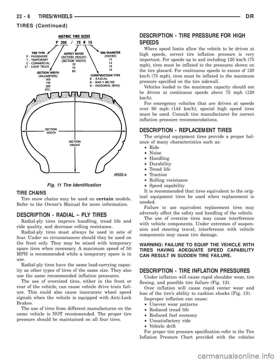
Fig. 11 Tire Identification
22 - 6 TIRES/WHEELSDR
TIRES (Continued)