2003 DODGE RAM frame
[x] Cancel search: framePage 616 of 2895
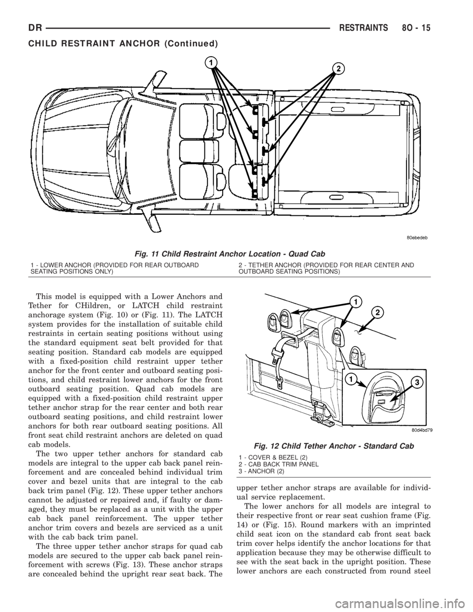
This model is equipped with a Lower Anchors and
Tether for CHildren, or LATCH child restraint
anchorage system (Fig. 10) or (Fig. 11). The LATCH
system provides for the installation of suitable child
restraints in certain seating positions without using
the standard equipment seat belt provided for that
seating position. Standard cab models are equipped
with a fixed-position child restraint upper tether
anchor for the front center and outboard seating posi-
tions, and child restraint lower anchors for the front
outboard seating position. Quad cab models are
equipped with a fixed-position child restraint upper
tether anchor strap for the rear center and both rear
outboard seating positions, and child restraint lower
anchors for both rear outboard seating positions. All
front seat child restraint anchors are deleted on quad
cab models.
The two upper tether anchors for standard cab
models are integral to the upper cab back panel rein-
forcement and are concealed behind individual trim
cover and bezel units that are integral to the cab
back trim panel (Fig. 12). These upper tether anchors
cannot be adjusted or repaired and, if faulty or dam-
aged, they must be replaced as a unit with the upper
cab back panel reinforcement. The upper tether
anchor trim covers and bezels are serviced as a unit
with the cab back trim panel.
The three upper tether anchor straps for quad cab
models are secured to the upper cab back panel rein-
forcement with screws (Fig. 13). These anchor straps
are concealed behind the upright rear seat back. Theupper tether anchor straps are available for individ-
ual service replacement.
The lower anchors for all models are integral to
their respective front or rear seat cushion frame (Fig.
14) or (Fig. 15). Round markers with an imprinted
child seat icon on the standard cab front seat back
trim cover helps identify the anchor locations for that
application because they may be otherwise difficult to
see with the seat back in the upright position. These
lower anchors are each constructed from round steel
Fig. 11 Child Restraint Anchor Location - Quad Cab
1 - LOWER ANCHOR (PROVIDED FOR REAR OUTBOARD
SEATING POSITIONS ONLY)2 - TETHER ANCHOR (PROVIDED FOR REAR CENTER AND
OUTBOARD SEATING POSITIONS)
Fig. 12 Child Tether Anchor - Standard Cab
1 - COVER & BEZEL (2)
2 - CAB BACK TRIM PANEL
3 - ANCHOR (2)
DRRESTRAINTS 8O - 15
CHILD RESTRAINT ANCHOR (Continued)
Page 617 of 2895

bar stock that is formed into a U-shape, then
securely welded at each end to the seat cushion
frame. They are each accessed from the front of their
respective seats, at each side where the seat back
meets the seat cushion. These lower anchors cannot
be adjusted or repaired and, if faulty or damaged,
they must be replaced as a unit with the seat cush-
ion frame. On quad cab models, if the lower anchors
have been bent or broken as a result of a vehicle col-
lision, the latch for the affected rear seat cushion
frame unit must also be replaced.WARNING: DURING AND FOLLOWING ANY SEAT
BELT OR CHILD RESTRAINT ANCHOR SERVICE,
CAREFULLY INSPECT ALL SEAT BELTS, BUCKLES,
MOUNTING HARDWARE, RETRACTORS, TETHER
STRAPS, AND ANCHORS FOR PROPER INSTALLA-
TION, OPERATION, OR DAMAGE. REPLACE ANY
BELT THAT IS CUT, FRAYED, OR TORN.
STRAIGHTEN ANY BELT THAT IS TWISTED.
TIGHTEN ANY LOOSE FASTENERS. REPLACE ANY
BELT THAT HAS A DAMAGED OR INOPERATIVE
BUCKLE OR RETRACTOR. REPLACE ANY BELT
THAT HAS A BENT OR DAMAGED LATCH PLATE
OR ANCHOR PLATE. REPLACE ANY CHILD
RESTRAINT ANCHOR OR THE UNIT TO WHICH THE
ANCHOR IS INTEGRAL THAT HAS BEEN BENT OR
DAMAGED. NEVER ATTEMPT TO REPAIR A SEAT
BELT OR CHILD RESTRAINT COMPONENT.
ALWAYS REPLACE DAMAGED OR FAULTY SEAT
BELT AND CHILD RESTRAINT COMPONENTS WITH
THE CORRECT, NEW AND UNUSED REPLACEMENT
PARTS LISTED IN THE DAIMLERCHRYSLER MOPAR
PARTS CATALOG.
OPERATION
See the owner's manual in the vehicle glove box for
more information on the proper use of all of the fac-
tory-installed child restraint anchors.
REMOVAL
The following procedure applies only to the rear
seat upper child tether straps used on quad cab mod-
els. The child restraint anchors used in other models
and locations are integral to other components and
cannot be serviced separately.
Fig. 13 Child Tether Strap - Quad Cab
1 - TETHER STRAP (3)
2 - CAB BACK PANEL
3 - SCREW (3)
Fig. 14 Child Restraint Lower Anchor - Standard
Cab Front Seat
1 - FRONT SEAT BACK
2 - LOWER ANCHOR (2) - PASSENGER SIDE OUTBOARD
SEATING POSITION ONLY
3 - LOWER ANCHOR MARKER (2)
4 - FRONT SEAT CUSHION
Fig. 15 Child Restraint Lower Anchor - Quad Cab
Rear Seat
1 - REAR SEAT BACK
2 - LOWER ANCHOR (2 PER OUTBOARD REAR SEATING
POSITION)
3 - REAR SEAT CUSHION
8O - 16 RESTRAINTSDR
CHILD RESTRAINT ANCHOR (Continued)
Page 694 of 2895
INSTALLATION
The right and left wiper arms are not interchange-
able. The right wiper arm is slightly longer than the
left. Be certain that each wiper arm is installed on
the proper wiper pivot.
(1) Place the wiper arm hinge in its over-center
position prior to attempting installation.
(2) The wiper arms are indexed to the wiper pivot
shafts with integral keys in the wiper arm pivot ends
and keyways in the wiper pivot shafts. Align the key
of the wiper arm to the keyway on the wiper pivot
shaft.
(3) Once the wiper blade is aligned, push the pivot
of the wiper arm down firmly and evenly over the
wiper pivot shaft until it is fully engaged. When the
wiper arm is fully engaged on the wiper pivot, the
spring-loaded latch (Fig. 19) will snap back into place
against the wiper arm pivot end.
(4) Gently lower the wiper arm until the wiper
blade is in position on the windshield glass.
WIPER BLADE
DESCRIPTION
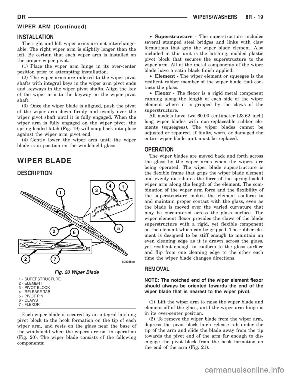
Each wiper blade is secured by an integral latching
pivot block to the hook formation on the tip of each
wiper arm, and rests on the glass near the base of
the windshield when the wipers are not in operation
(Fig. 20). The wiper blade consists of the following
components:²Superstructure- The superstructure includes
several stamped steel bridges and links with claw
formations that grip the wiper blade element. Also
included in this unit is the latching, molded plastic
pivot block that secures the superstructure to the
wiper arm. All of the metal components of the wiper
blade have a satin black finish applied.
²Element- The wiper element or squeegee is the
resilient rubber member of the wiper blade that con-
tacts the glass.
²Flexor- The flexor is a rigid metal component
running along the length of each side of the wiper
element where it is gripped by the claws of the
superstructure.
All models have two 60.00 centimeter (23.62 inch)
long wiper blades with non-replaceable rubber ele-
ments (squeegees). The wiper blades cannot be
adjusted or repaired. If faulty, worn, or damaged the
entire wiper blade unit must be replaced.
OPERATION
The wiper blades are moved back and forth across
the glass by the wiper arms when the wipers are
being operated. The wiper blade superstructure is
the flexible frame that grips the wiper blade element
and evenly distributes the force of the spring-loaded
wiper arm along the length of the element. The com-
bination of the wiper arm force and the flexibility of
the superstructure makes the element conform to
and maintain proper contact with the glass, even as
the blade is moved over the varied curvature that
may be encountered across the glass surface. The
wiper element flexor provides the claws of the blade
superstructure with a rigid, yet flexible component
on the element which can be gripped. The rubber ele-
ment is designed to be stiff enough to maintain an
even cleaning edge as it is drawn across the glass,
yet resilient enough to conform to the glass surface
and flip from one cleaning edge to the other each
time the wiper blade changes directions.
REMOVAL
NOTE: The notched end of the wiper element flexor
should always be oriented towards the end of the
wiper blade that is nearest to the wiper pivot.
(1) Lift the wiper arm to raise the wiper blade and
element off of the glass, until the wiper arm hinge is
in its over-center position.
(2) To remove the wiper blade from the wiper arm,
depress the pivot block latch release tab under the
tip of the arm and slide the blade away from the tip
towards the pivot end of the arm far enough to dis-
engage the pivot block from the hook formation on
the end of the arm (Fig. 21).
Fig. 20 Wiper Blade
1 - SUPERSTRUCTURE
2 - ELEMENT
3 - PIVOT BLOCK
4 - RELEASE TAB
5 - PIVOT PIN
6 - CLAWS
7 - FLEXOR
DRWIPERS/WASHERS 8R - 19
WIPER ARM (Continued)
Page 1179 of 2895
CONNECTOR NAME/NUMBER COLOR LOCATION FIG.
Blower Motor BK Behind Right Side of Instrument
PanelN/S
Blower Motor Resistor Block BK Behind Right Side of Instrument
PanelN/S
Brake Lamp Switch BK Top of Brake Pedal Arm 32, 37, 39
Brake Provision-Electric Rear of Engine 26, 27
Brake Transmission Shift Interlock
SolenoidBK Near Steering Column 33, 37, 39
C100 BK Near G107 21, 22, 23, 24, 25
C102 Near Integrated Power Module 28
C106 (5.7L) BK Left Rear Engine 5
C107 (5.7L) BK Left Rear Engine 5
C112 (Diesel) BK Near T/O for Water In Fuel Sensor N/S
C113 BK Left Side Engine 10
C114 BK Left side Engine 10
C115 (Diesel) BK Left Side Engine 10
C130 BK Left Rear of Engine 21, 22, 23, 24, 26
C200 GY Under Instrument Panel 40
C201 WT Near Left Instrument Panel
Speaker37, 39
C205 BK Left Rear Side of Engine
CompartmentN/S
C206 BK Right Instrument Panel 37, 40, 46
C216 BK Middle Left Frame 26, 28, 48
C217 BK Middle Left Frame 26, 28, 37, 48
C218 WT Left Side of Instrument Panel 26, 27, 41, 44
C219 GY Left Side of Instrument Panel 26, 27, 33, 37, 39, 41
C220 WT Left Side of Instrument Panel 37, 39, 41
C301 WT Right Kick Panel 41
C302 BK Left Front Door 41
C304 WT Left Side of Instrument Panel 42, 44, 45
C305 BK At Left Front Door 42, 44, 45
C306 WT Middle Front of Door 43, 45
C307 BK Near Right License Lamp 48, 49
C308 WT Under Instrument Panel 40, 41
C309 WT Left Side of Instrument Panel 39, 41, 44, 45
C310 BK Left Rear of Frame 48, 49
C311 BK Left Rear of Frame 44, 45
C312 WT Under Seat N/S
C313 DK GY At Driver Seat N/S
C314 DK GY At Driver Seat N/S
C315 DK GY At Driver Seat N/S
C316 BK At Passenger Seat N/S
8W - 91 - 2 8W-91 CONNECTOR/GROUND/SPLICE LOCATIONDR
CONNECTOR/GROUND/SPLICE LOCATION (Continued)
Page 1180 of 2895
CONNECTOR NAME/NUMBER COLOR LOCATION FIG.
C317 BK At Passenger Seat N/S
C319 BK Bottom Left of Left Door N/S
C322 DK GY Left Rear of Frame N/S
C323 BK Left Side of Instrument Panel N/S
C327 BK Right Rear Fender 48, 49
C328 BK Left Rear Fender 48, 49, 50
Camshaft Position Sensor GY Right Front Side of Engine 3, 6, 8, 9
Capacitor Left Rear of Engine Compartment N/S
Center High Mounted Stop
Lamp/Cargo LampBK Rear of Cab 47
Cigar Lighter Outlet NAT Rear of Cigar Lighter 34, 37, 38
Clearance Lamp No. 1 BK Left Roof 46
Clearance Lamp No. 2 BK Left-Center Roof 46
Clearance Lamp No. 3 BK Center Roof 46
Clearance Lamp No. 4 BK Right-Center Roof 46
Clearance Lamp No. 5 BK Right Roof 46
Clockspring C1 BK Steering Column 33
Clockspring C2 YL Steering Column 33
Clockspring C3 BK Steering Column N/S
Clockspring C4 BK Steering Column N/S
Clutch Interlock Brake Switch BK At Clutch Pedal 26, 27
Coil On Plug No.1 BK Left Top Side of Intake Manifold 4
Coil On Plug No.2 BK Right Top Side of Intake Manifold 3
Coil On Plug No.3 BK Left Top Side of Intake Manifold 4
Coil On Plug No.4 BK Right Top Side of Intake Manifold 3
Coil On Plug No.5 BK Left Top Side of Intake Manifold 4
Coil On Plug No.6 BK Right Top Side of Intake Manifold 3
Coil On Plug No.7 BK Left Top Side of Intake Manifold 4
Coil On Plug No.8 BK Right Top Side of Intake Manifold 3
Compass/Mini-Trip Computer BK In Overhead Console N/S
Condenser Fan BK Near Condenser 26, 27
Controller Anti-Lock Brake C1 BK Left Fender Side Shield 26, 27, 28
Controller Anti-Lock Brake C2
(ABS)BK Left Fender Side Shield 26, 28
Crankshaft Position Sensor BK Right Rear of Engine Block 3, 6, 8, 9
Cylinder Lock Switch-Driver
(Premium)BK In Left Front Door 42
Cylinder Lock Switch-Passenger
(Premium)LT GY In Right Front Door N/S
Data Link Connector BK Left Bottom of Instrument Panel 37, 39
Data Link Connector - Engine
(Diesel)BK Near T/O for Water In Fuel Sensor N/S
Dome Lamp BK Center of Headliner N/S
DR8W-91 CONNECTOR/GROUND/SPLICE LOCATION 8W - 91 - 3
CONNECTOR/GROUND/SPLICE LOCATION (Continued)
Page 1188 of 2895
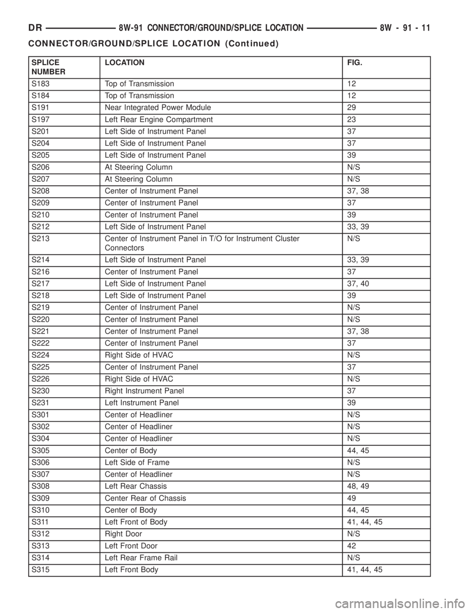
SPLICE
NUMBERLOCATION FIG.
S183 Top of Transmission 12
S184 Top of Transmission 12
S191 Near Integrated Power Module 29
S197 Left Rear Engine Compartment 23
S201 Left Side of Instrument Panel 37
S204 Left Side of Instrument Panel 37
S205 Left Side of Instrument Panel 39
S206 At Steering Column N/S
S207 At Steering Column N/S
S208 Center of Instrument Panel 37, 38
S209 Center of Instrument Panel 37
S210 Center of Instrument Panel 39
S212 Left Side of Instrument Panel 33, 39
S213 Center of Instrument Panel in T/O for Instrument Cluster
ConnectorsN/S
S214 Left Side of Instrument Panel 33, 39
S216 Center of Instrument Panel 37
S217 Left Side of Instrument Panel 37, 40
S218 Left Side of Instrument Panel 39
S219 Center of Instrument Panel N/S
S220 Center of Instrument Panel N/S
S221 Center of Instrument Panel 37, 38
S222 Center of Instrument Panel 37
S224 Right Side of HVAC N/S
S225 Center of Instrument Panel 37
S226 Right Side of HVAC N/S
S230 Right Instrument Panel 37
S231 Left Instrument Panel 39
S301 Center of Headliner N/S
S302 Center of Headliner N/S
S304 Center of Headliner N/S
S305 Center of Body 44, 45
S306 Left Side of Frame N/S
S307 Center of Headliner N/S
S308 Left Rear Chassis 48, 49
S309 Center Rear of Chassis 49
S310 Center of Body 44, 45
S311 Left Front of Body 41, 44, 45
S312 Right Door N/S
S313 Left Front Door 42
S314 Left Rear Frame Rail N/S
S315 Left Front Body 41, 44, 45
DR8W-91 CONNECTOR/GROUND/SPLICE LOCATION 8W - 91 - 11
CONNECTOR/GROUND/SPLICE LOCATION (Continued)
Page 1307 of 2895
(11) Remove the (3) bolts that attach the front axle
to the left engine bracket.
(12) Lower the front axle.
(13) Remove the (6) through bolts
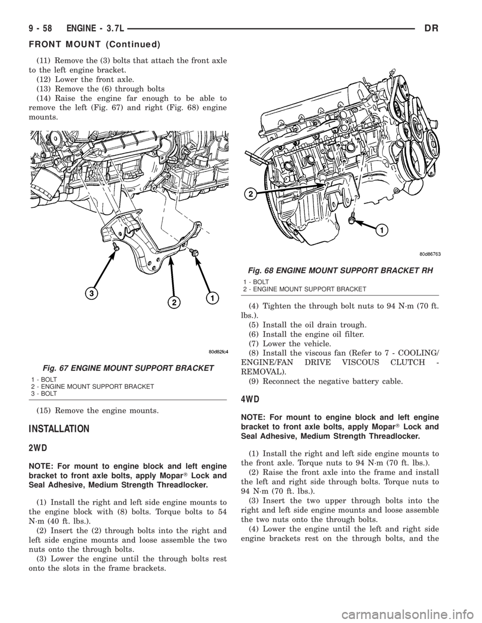
(14) Raise the engine far enough to be able to
remove the left (Fig. 67) and right (Fig. 68) engine
mounts.
(15) Remove the engine mounts.
INSTALLATION
2WD
NOTE: For mount to engine block and left engine
bracket to front axle bolts, apply MoparTLock and
Seal Adhesive, Medium Strength Threadlocker.
(1) Install the right and left side engine mounts to
the engine block with (8) bolts. Torque bolts to 54
N´m (40 ft. lbs.).
(2) Insert the (2) through bolts into the right and
left side engine mounts and loose assemble the two
nuts onto the through bolts.
(3) Lower the engine until the through bolts rest
onto the slots in the frame brackets.(4) Tighten the through bolt nuts to 94 N´m (70 ft.
lbs.).
(5) Install the oil drain trough.
(6) Install the engine oil filter.
(7) Lower the vehicle.
(8) Install the viscous fan (Refer to 7 - COOLING/
ENGINE/FAN DRIVE VISCOUS CLUTCH -
REMOVAL).
(9) Reconnect the negative battery cable.
4WD
NOTE: For mount to engine block and left engine
bracket to front axle bolts, apply MoparTLock and
Seal Adhesive, Medium Strength Threadlocker.
(1) Install the right and left side engine mounts to
the front axle. Torque nuts to 94 N´m (70 ft. lbs.).
(2) Raise the front axle into the frame and install
the left and right side through bolts. Torque nuts to
94 N´m (70 ft. lbs.).
(3) Insert the two upper through bolts into the
right and left side engine mounts and loose assemble
the two nuts onto the through bolts.
(4) Lower the engine until the left and right side
engine brackets rest on the through bolts, and the
Fig. 67 ENGINE MOUNT SUPPORT BRACKET
1 - BOLT
2 - ENGINE MOUNT SUPPORT BRACKET
3 - BOLT
Fig. 68 ENGINE MOUNT SUPPORT BRACKET RH
1 - BOLT
2 - ENGINE MOUNT SUPPORT BRACKET
9 - 58 ENGINE - 3.7LDR
FRONT MOUNT (Continued)
Page 1314 of 2895
OIL PAN
DESCRIPTION
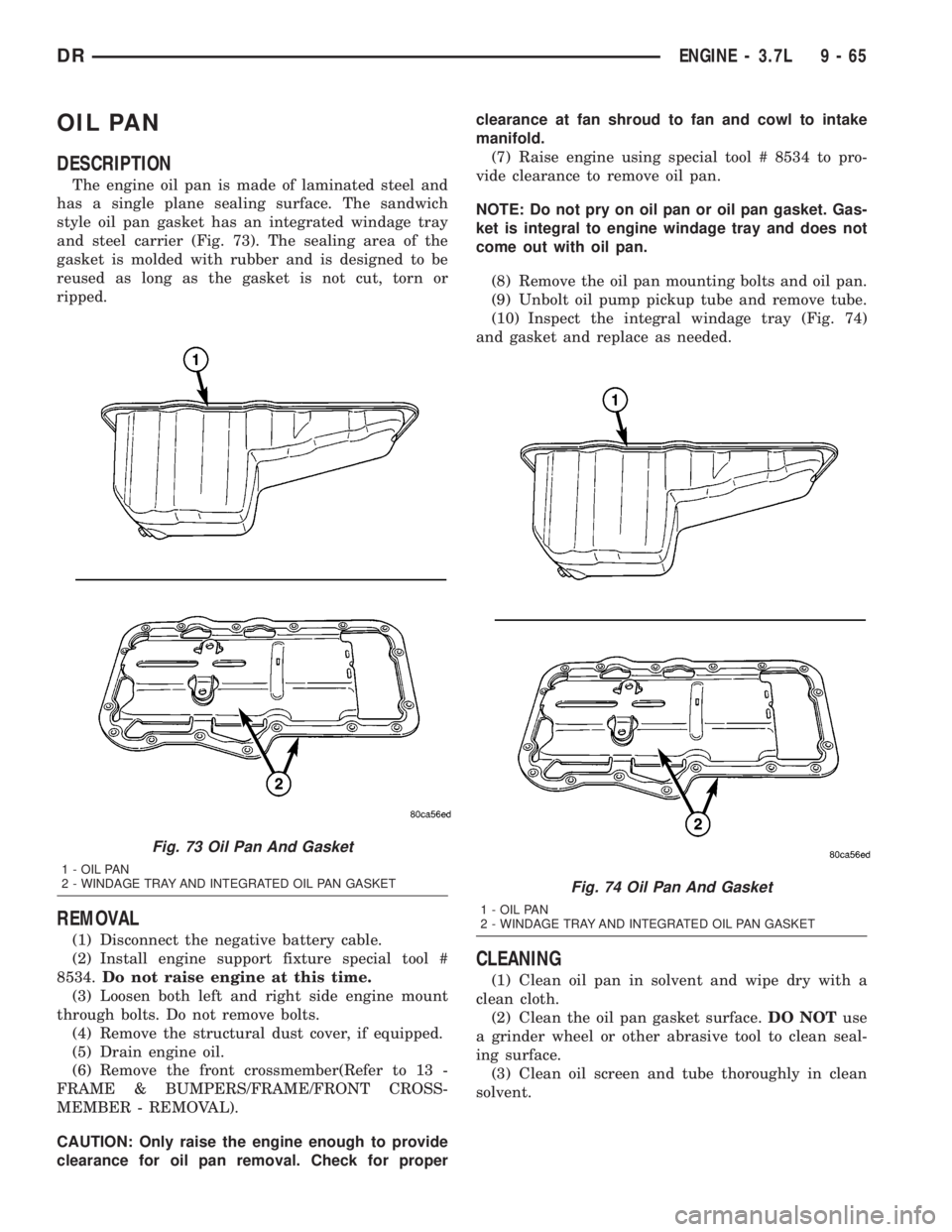
The engine oil pan is made of laminated steel and
has a single plane sealing surface. The sandwich
style oil pan gasket has an integrated windage tray
and steel carrier (Fig. 73). The sealing area of the
gasket is molded with rubber and is designed to be
reused as long as the gasket is not cut, torn or
ripped.
REMOVAL
(1) Disconnect the negative battery cable.
(2) Install engine support fixture special tool #
8534.Do not raise engine at this time.
(3) Loosen both left and right side engine mount
through bolts. Do not remove bolts.
(4) Remove the structural dust cover, if equipped.
(5) Drain engine oil.
(6) Remove the front crossmember(Refer to 13 -
FRAME & BUMPERS/FRAME/FRONT CROSS-
MEMBER - REMOVAL).
CAUTION: Only raise the engine enough to provide
clearance for oil pan removal. Check for properclearance at fan shroud to fan and cowl to intake
manifold.
(7) Raise engine using special tool # 8534 to pro-
vide clearance to remove oil pan.
NOTE: Do not pry on oil pan or oil pan gasket. Gas-
ket is integral to engine windage tray and does not
come out with oil pan.
(8) Remove the oil pan mounting bolts and oil pan.
(9) Unbolt oil pump pickup tube and remove tube.
(10) Inspect the integral windage tray (Fig. 74)
and gasket and replace as needed.
CLEANING
(1) Clean oil pan in solvent and wipe dry with a
clean cloth.
(2) Clean the oil pan gasket surface.DO NOTuse
a grinder wheel or other abrasive tool to clean seal-
ing surface.
(3) Clean oil screen and tube thoroughly in clean
solvent.
Fig. 73 Oil Pan And Gasket
1 - OIL PAN
2 - WINDAGE TRAY AND INTEGRATED OIL PAN GASKET
Fig. 74 Oil Pan And Gasket
1 - OIL PAN
2 - WINDAGE TRAY AND INTEGRATED OIL PAN GASKET
DRENGINE - 3.7L 9 - 65