2003 DODGE RAM frame
[x] Cancel search: framePage 260 of 2895
(6) Install the right cable to the front cable.
(7) Adjust the brake cable at the equalizer and
using the adjuster nut.
INSTALLATION - LEFT REAR CABLE
(1) Install the brake cable to the brake lever (Fig.
61).
(2) Install the brake cable to the frame bracket.
(3) Install the left brake cable to the equalizer.
(4) Adjust the brake cable at the equalizer and
adjuster nut.
SHOES
REMOVAL
(1) Raise and support the vehicle.
(2) Remove the tire and wheel assembly.
(3) Remove the disc brake caliper,(Refer to 5 -
BRAKES/HYDRAULIC/MECHANICAL/DISC
BRAKE CALIPERS - REMOVAL).
(4) Remove the disc brake rotor, (Refer to 5 -
BRAKES/HYDRAULIC/MECHANICAL/ROTORS -
REMOVAL).
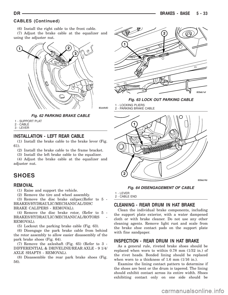
(5) Lockout the parking brake cable (Fig. 63).
(6) Disengage the park brake cable from behind
the rotor assembly to allow easier disassembly of the
park brake shoes (Fig. 64).
(7) Remove the axleshaft (Fig. 65) (Refer to 3 -
DIFFERENTIAL & DRIVELINE/REAR AXLE - 9 1/4/
AXLE SHAFTS - REMOVAL).
(8) Disassemble the rear park brake shoes (Fig.
56).
CLEANING - REAR DRUM IN HAT BRAKE
Clean the individual brake components, including
the support plate exterior, with a water dampened
cloth or with brake cleaner. Do not use any other
cleaning agents. Remove light rust and scale from
the brake shoe contact pads on the support plate
with fine sandpaper.
INSPECTION - REAR DRUM IN HAT BRAKE
As a general rule, riveted brake shoes should be
replaced when worn to within 0.78 mm (1/32 in.) of
the rivet heads. Bonded lining should be replaced
when worn to a thickness of 1.6 mm (1/16 in.).
Examine the lining contact pattern to determine if
the shoes are bent or the drum is tapered. The lining
should exhibit contact across its entire width. Shoes
exhibiting contact only on one side should be
Fig. 62 PARKING BRAKE CABLE
1 - SUPPORT PLAT
2 - CABLE
3 - LEVER
Fig. 63 LOCK OUT PARKING CABLE
1 - LOCKING PLIERS
2 - PARKING BRAKE CABLE
Fig. 64 DISENGAGEMENT OF CABLE
1 - LEVER
2 - CABLE END
DRBRAKES - BASE 5 - 33
CABLES (Continued)
Page 384 of 2895

²Cyclic Redundancy Check (CRC) Byte- This
byte is used to detect errors during a message trans-
mission.
²In-Frame Response (IFR) byte(s)-Ifa
response is required from the target module(s), it can
be sent during this frame. This function is described
in greater detail in the following paragraph.
The IFR consists of one or more bytes, which are
transmitted during a message. If the sending module
requires information to be received immediately, the
target module(s) can send data over the bus during
the original message. This allows the sending module
to receive time-critical information without having to
wait for the target module to access the bus. After
the IFR is received, the sending module broadcasts
an End of Frame (EOF) message and releases control
of the bus.
The PCI data bus can be monitored using the
DRBIIItscan tool. It is possible, however, for the bus
to pass all DRBIIIttests and still be faulty if the
voltage parameters are all within the specified range
and false messages are being sent.
CONTROLLER ANTILOCK
BRAKE
DESCRIPTION
The Controler Antilock Brake (CAB) is mounted to
the Hydraulic Control Unit (HCU) and operates the
ABS system (Fig. 1).
OPERATION
The CAB voltage source is through the ignition
switch in the RUN position. The CAB contains a self
check program that illuminates the ABS warning
light when a system fault is detected. Faults are
stored in a diagnostic program memory and are
accessible with the DRB III scan tool. ABS faults
remain in memory until cleared, or until after the
vehicle is started approximately 50 times. Stored
faults arenoterased if the battery is disconnected.
NOTE: If the CAB is being replaced with a new CAB
is must be reprogrammed with the use of a DRB III.
REMOVAL
(1) Remove the negative battery cable from the
battery.
(2) Pull up on the CAB harness connector release
and remove connector.
(3) Remove the CAB mounting bolts.
(4) Remove the pump connector from the CAB.
(5) Remove the CAB from the HCU.
INSTALLATION
NOTE: If the CAB is being replaced with a new CAB
is must be reprogrammed with the use of a DRB III.
(1) Install CAB to the HCU.
(2) Install the pump connector to the CAB.
(3) Install mounting bolts. Tighten to 2 N´m (16 in.
lbs.).
(4) Install the wiring harness connector to the
CAB and push down on the release to secure the con-
nector.
(5) Install negative battery cable to the battery.
DATA LINK CONNECTOR
DESCRIPTION - DATA LINK CONNECTOR
The Data Link Connector (DLC) is located at the
lower edge of the instrument panel near the steering
column.
OPERATION - DATA LINK CONNECTOR
The 16±way data link connector (diagnostic scan
tool connector) links the Diagnostic Readout Box
(DRB) scan tool or the Mopar Diagnostic System
(MDS) with the Powertrain Control Module (PCM).
Fig. 1 HYDRAULIC CONTROL UNIT
1 - HYDRAULIC CONTROL UNIT
2 - MOUNTING BOLTS
DRELECTRONIC CONTROL MODULES 8E - 3
COMMUNICATION (Continued)
Page 412 of 2895

SPECIAL TOOLS
BATTERY SYSTEM SPECIAL TOOLS
BATTERY
DESCRIPTION
A large capacity, low-maintenance storage battery
(Fig. 4) is standard factory-installed equipment on
this model. Models equipped with a diesel engine
must utilize two 12-volt batteries connected in paral-
lel. Male post type terminals made of a soft lead
material protrude from the top of the molded plastic
battery case to provide the means for connecting the
battery to the vehicle electrical system. The battery
positive terminal post is physically larger in diameter
than the negative terminal post to ensure proper bat-
tery connection. The lettersPOSandNEGare also
molded into the top of the battery case adjacent to
their respective positive and negative terminal posts
for identification confirmation. Refer to Battery
Cables for more information on the battery cables
that connect the battery to the vehicle electrical sys-
tem.
The battery is made up of six individual cells that
are connected in series. Each cell contains positively
charged plate groups that are connected with lead
straps to the positive terminal post, and negatively
charged plate groups that are connected with lead
straps to the negative terminal post. Each plate con-
sists of a stiff mesh framework or grid coated with
lead dioxide (positive plate) or sponge lead (negative
plate). Insulators or plate separators made of a non-
conductive material are inserted between the positive
and negative plates to prevent them from contacting
or shorting against one another. These dissimilar
metal plates are submerged in a sulfuric acid and
water solution called an electrolyte.
The factory-installed battery has a built-in test
indicator (hydrometer). The color visible in the sight
glass of the indicator will reveal the battery condi-
tion. Refer to Standard Procedures for the proper
built-in indicator test procedures.The factory-in-
stalled low-maintenance battery has non-re-
movable battery cell caps.Water cannot be added
to this battery. The battery is not sealed and has
vent holes in the cell caps. The chemical composition
of the metal coated plates within the low-mainte-
nance battery reduces battery gassing and water
loss, at normal charge and discharge rates. There-
fore, the battery should not require additional water
in normal service. Rapid loss of electrolyte can be
caused by an overcharging condition.
DIAGNOSIS AND TESTING - BATTERY
The battery must be completely charged and the
terminals should be properly cleaned and inspected
before diagnostic procedures are performed. Refer to
Battery System Cleaning for the proper cleaning pro-
cedures, and Battery System Inspection for the
proper battery inspection procedures. Refer to Stan-
dard Procedures for the proper battery charging pro-
cedures.
Micro 420 Battery Tester
Fig. 4 Low-Maintenance Battery - Typical
1 - POSITIVE POST
2 - VENT
3 - CELL CAP
4 - TEST INDICATOR (IF EQUIPPED)
5 - CELL CAP
6 - VENT
7 - NEGATIVE POST
8 - GREEN BALL
9 - ELECTROLYTE LEVEL
10 - PLATE GROUPS
11 - LOW-MAINTENANCE BATTERY
DRBATTERY SYSTEM 8F - 7
BATTERY SYSTEM (Continued)
Page 439 of 2895
SPECIFICATIONS - TORQUE - STARTING
SYSTEM
DESCRIPTION N´m Ft. Lbs. In. Lbs.
Battery Cable Eyelet Nut at
Solenoid (large nut - gas engines)25 19 221
Battery Cable Eyelet Nut at
Solenoid (large nut - diesel engine)14 - 120
Starter Solenoid Nut (small nut -
diesel engine)6-55
Starter Mounting Bolts - Gas
Engines68 50 -
Starter Mounting Nut - Gas Engines 68 50 -
Starter Mounting Bolts - Diesel 43 32 -
STARTER MOTOR
DIAGNOSIS AND TESTING - STARTER MOTOR
Correct starter motor operation can be confirmed
by performing the following free running bench test.
This test can only be performed with starter motor
removed from vehicle. Refer to Specifications for
starter motor specifications.
(1) Remove starter motor from vehicle. Refer to
Starter Motor Removal and Installation.
(2) Mount starter motor securely in a soft-jawed
bench vise. The vise jaws should be clamped on the
mounting flange of starter motor. Never clamp on
starter motor by field frame.
(3) Connect a suitable volt-ampere tester and a
12-volt battery to starter motor in series, and set
ammeter to 100 ampere scale. See instructions pro-
vided by manufacturer of volt-ampere tester being
used.
(4) Install jumper wire from solenoid terminal to
solenoid battery terminal. The starter motor should
operate. If starter motor fails to operate, replace
faulty starter motor assembly.
(5) Adjust carbon pile load of tester to obtain free
running test voltage. Refer to Specifications for
starter motor free running test voltage specifications.
(6) Note reading on ammeter and compare reading
to free running test maximum amperage draw. Refer
to Specifications for starter motor free running test
maximum amperage draw specifications.
(7) If ammeter reading exceeds maximum amper-
age draw specification, replace faulty starter motor
assembly.
STARTER SOLENOID
This test can only be performed with starter motor
removed from vehicle.(1) Remove starter motor from vehicle. Refer to
Starter Motor Removal and Installation.
(2) Disconnect wire from solenoid field coil termi-
nal.
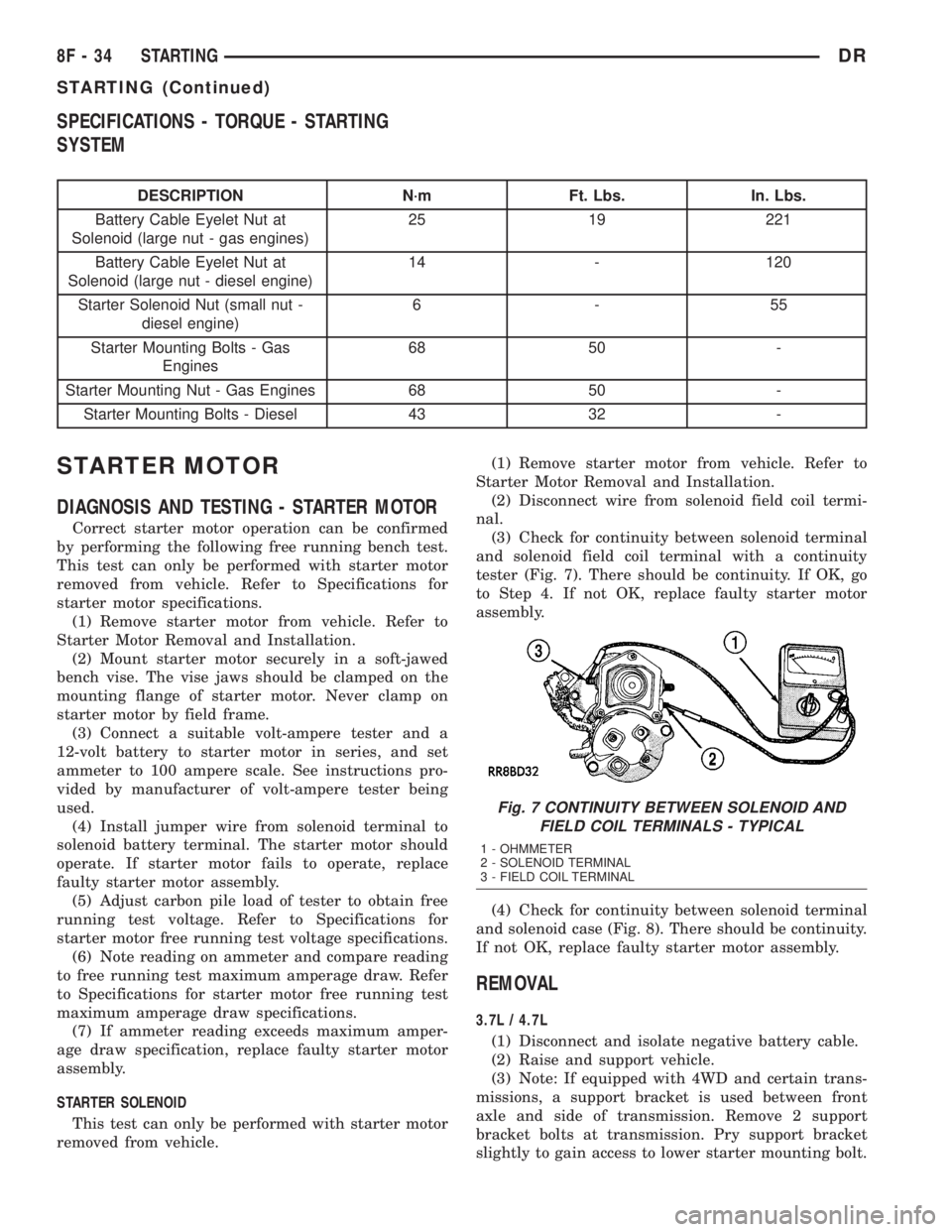
(3) Check for continuity between solenoid terminal
and solenoid field coil terminal with a continuity
tester (Fig. 7). There should be continuity. If OK, go
to Step 4. If not OK, replace faulty starter motor
assembly.
(4) Check for continuity between solenoid terminal
and solenoid case (Fig. 8). There should be continuity.
If not OK, replace faulty starter motor assembly.
REMOVAL
3.7L / 4.7L
(1) Disconnect and isolate negative battery cable.
(2) Raise and support vehicle.
(3) Note: If equipped with 4WD and certain trans-
missions, a support bracket is used between front
axle and side of transmission. Remove 2 support
bracket bolts at transmission. Pry support bracket
slightly to gain access to lower starter mounting bolt.
Fig. 7 CONTINUITY BETWEEN SOLENOID AND
FIELD COIL TERMINALS - TYPICAL
1 - OHMMETER
2 - SOLENOID TERMINAL
3 - FIELD COIL TERMINAL
8F - 34 STARTINGDR
STARTING (Continued)
Page 451 of 2895

the element grids to the heated seat module through
the seat wire harness.
One temperature sensor is used for each front seat,
and it is located in the center insert area of the seat
cushion element. The heated seat sensors and their
pigtail wires are also captured between a covering
and the adhesive foam rubber backing. The heated
seat sensors are Negative Thermal Coefficient (NTC)
thermistors. The sensors for both front seats receive
a voltage feed from a single output of the heated seat
module, but the module receives individual sensor
inputs from the driver side and passenger side sen-
sors.
The heated seat elements and sensors should not
be repaired. If damaged or faulty, the heated seat ele-
ment assembly must be replaced.
OPERATION
One end of the heated seat element resistor wire is
connected to ground at all times through a splice in
the heated seat module ground circuit. Battery cur-
rent is directed to the other end of the heated seat
element resistor wire by the energized N-channel
Field Effect Transistor (N-FET) located within the
heated seat module. The heated seat module will
energize the N-FET only when the heated seat
switch is in the Low or High position and the heated
seat sensor indicates that the seat cushion surface
temperature is below the selected (Low or High) tem-
perature set point. As electrical current passes
through the heating element grid, the resistance of
the wire used in the element disperses some of that
electrical current in the form of heat. The heat pro-
duced by the heated seat element grid then radiates
through the seat trim cover, warming its occupant.
The resistance of the heated seat sensor increases
and decreases as the surface temperature of the seat
cushion cover changes. The heated seat module sup-
plies each sensor with a 5v voltage feed, then uses
the sensor resistance to determine when the heated
seat element grids need to be cycled on or off in order
to maintain the selected temperature set point.
DIAGNOSIS AND TESTING - HEATED SEAT
ELEMENT
The heated seat module will self-diagnose shorted
or open heated seat element circuits and sensor cir-
cuits. Refer to Heated Seat System Diagnosis and
Testing in this section for additional diagnosis and
testing procedures. To manually check the heated
seat element, proceed as follows. The wire harness
connectors for the seat cushion and seat back heating
elements and sensor are located on the right side of
the seat, near the edge of the seat cushion frame.
The proper connector can be identified by the foam
wrapping.NOTE: When checking heated seat elements for
continuity, be certain to move the heating element
being checked. Moving the element, such as sitting
in the seat will eliminate the possibility of an inter-
mittent open in the element which would only be
evident if the element was in a certain position.
Failure to check the element in various positions
could result in an incomplete test.
(1) Position the appropriate seat in the full for-
ward position.
(2) Make certain the ignition switch is in the OFF
position.
(3) Disconnect the heated seat element connector
which requires testing. Check for continuity between
the two heated seat element circuit cavities while
moving the appropriate seat cushion. Refer toWir-
ingfor the location of complete heated seat system
wiring diagrams. There should be continuity. If OK,
the elements within the seat assembly test OK, go to
Step 4. If not OK, replace the faulty seat heating ele-
ment, refer to the procedure in this section.
(4) Test the seat wire harness between the heated
seat module connector and the appropriate heated
seat wire harness connector for shorted or open cir-
cuits. If OK, element is OK, proceed with testing the
heated seat sensor and module. If not OK, repair the
shorted or open seat wire harness as required.
REMOVAL
Do not remove the heating element from the seat
or seat back cushion. The original element is perma-
nently attached to the seat cushions and cannot be
removed without damaging the cushion. The replace-
ment heating element is designed to be applied
directly over the original seat heating element.
(1) Disconnect and isolate the negative battery
cable.
(2) Remove the appropriate seat cushion or seat
back trim cover. Refer to the Body section of this
manual for the procedures.
(3) Disconnect the inoperative heated seat cushion
or seat back element electrical connectors.
(4) Locate the wires leading from the inoperative
heating element and cut them off flush with the edge
of the original heating element.
INSTALLATION
(1) Peel off the adhesive backing on the back of the
replacement heating element and stick directly over
the original heating element (Fig. 3).
CAUTION: During the installation of the replace-
ment heating element, be careful not to fold or
crease the element assembly. Folds or creases will
cause premature failure.
8G - 6 HEATED SEAT SYSTEMDR
HEATED SEAT ELEMENT (Continued)
Page 595 of 2895
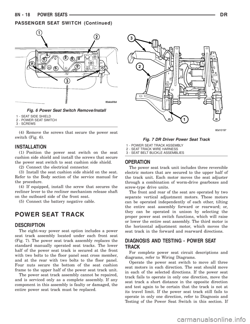
(4) Remove the screws that secure the power seat
switch (Fig. 6).
INSTALLATION
(1) Position the power seat switch on the seat
cushion side shield and install the screws that secure
the power seat switch to seat cushion side shield.
(2) Connect the electrical connector.
(3) Install the seat cushion side shield on the seat.
Refer to the Body section of the service manual for
the procedure.
(4) If equipped, install the screw that secures the
recliner lever to the recliner mechanism release shaft
on the outboard side of the front seat.
(5) Connect the battery negative cable.
POWER SEAT TRACK
DESCRIPTION
The eight-way power seat option includes a power
seat track assembly located under each front seat
(Fig. 7). The power seat track assembly replaces the
standard manually operated seat tracks. The lower
half of the power seat track is secured at the front
with two bolts to the floor panel seat cross member,
and at the rear with two bolts to the floor panel.
Four nuts secure the bottom of the seat cushion
frame to the upper half of the power seat track unit.
The power seat track assembly cannot be repaired,
and is serviced only as a complete assembly. If any
component in this assembly is faulty or damaged, the
entire power seat track must be replaced.
OPERATION
The power seat track unit includes three reversible
electric motors that are secured to the upper half of
the track unit. Each motor moves the seat adjuster
through a combination of worm-drive gearboxes and
screw-type drive units.
The front and rear of the seat are operated by two
separate vertical adjustment motors. These motors
can be operated independently of each other, tilting
the entire seat assembly forward or rearward; or,
they can be operated in unison by selecting the
proper power seat switch functions, which will raise
or lower the entire seat assembly. The third motor is
the horizontal adjustment motor, which moves the
seat track in the forward and rearward directions.
DIAGNOSIS AND TESTING - POWER SEAT
TRACK
For complete power seat circuit descriptions and
diagrams, refer to Wiring Diagrams.
Operate the power seat switch to move all three
seat motors in each direction. The seat should move
in each of the selected directions. If the power seat
track fails to operate in only one direction, move the
seat track a short distance in the opposite direction
and test again to be certain that the track is not at
its travel limit. If the power seat track still fails to
operate in only one direction, refer to Diagnosis and
Testing of the Power Seat Switch in this section. If
Fig. 6 Power Seat Switch Remove/Install
1 - SEAT SIDE SHIELD
2 - POWER SEAT SWITCH
3 - SCREWS
Fig. 7 DR Driver Power Seat Track
1 - POWER SEAT TRACK ASSEMBLY
2 - SEAT TRACK WIRE HARNESS
3 - SEAT BELT BUCKLE ASSEMBLIES
8N - 18 POWER SEATSDR
PASSENGER SEAT SWITCH (Continued)
Page 597 of 2895
to a molded plastic back panel and to the seat back
frame.
The power lumbar adjuster cannot be repaired, and
is serviced only as a unit with the seat back frame. If
the power lumbar adjuster or the seat back frame
are damaged or faulty, the entire seat back frame
unit must be replaced (Refer to 23 - BODY/SEATS/
SEAT BACK - REMOVAL).
OPERATION
The power lumbar adjuster mechanism includes a
reversible electric motor that is secured to the
inboard side of the seat back panel and is connected
to a worm-drive gearbox. The motor and gearbox
operate the lumbar adjuster mechanism in the center
of the seat back by extending and retracting a cable
that actuates a lever. The action of this lever com-
presses or relaxes a grid of flexible slats. The more
this grid is compressed, the more the slats bow out-
ward against the center of the seat back padding,
providing additional lumbar support.
DIAGNOSIS AND TESTING - LUMBAR MOTOR
Actuate the power lumbar switch to move the
power lumbar adjuster in each direction. The power
lumbar adjuster should move in both directions. It
should be noted that the power lumber adjuster nor-
mally operates very quietly and exhibits little visible
movement. If the power lumbar adjuster fails to oper-
ate in only one direction, move the adjuster a short
distance in the opposite direction and test again to be
certain that the adjuster is not at its travel limit. If
the power lumbar adjuster fails to operate in onlyone direction, Test the appropriate power seat switch
as described in this group. If the power lumbar
adjuster fails to operate in either direction, perform
the following tests. For complete circuit diagrams,
refer toWiring.
(1) Check the power seat circuit breaker. If OK, go
to Step 2. If not OK, replace the faulty power seat
circuit breaker.
(2) Check for battery voltage at the power seat cir-
cuit breaker. If OK, go to Step 3. If not OK, repair
the open fused B(+) circuit to the fuse in the Inte-
grated Power Module as required.
(3) Remove the outboard seat cushion side shield
from the seat. Disconnect the seat wire harness con-
nector from the power lumbar switch connector
receptacle. Check for battery voltage at the fused
B(+) circuit cavity of the power seat wire harness
connector for the power lumbar switch. If OK, go to
Step 4. If not OK, repair the open fused B(+) circuit
to the power seat as required.
(4) Check for continuity between the ground cir-
cuit cavity of the power seat wire harness connector
for the power lumbar switch and a good ground.
There should be continuity. If OK, go to Step 5. If not
OK, repair the open ground circuit to ground as
required.
(5) Test the power lumbar switch. . If the switch
tests OK, test the circuits of the power seat wire har-
ness between the power lumbar adjuster motor and
the power lumbar switch for shorts or opens. If the
circuits check OK, replace the faulty seat back frame
assembly. If the circuits are not OK, repair the power
seat wire harness as required.
8N - 20 POWER SEATSDR
LUMBAR MOTOR (Continued)
Page 603 of 2895
DIAGNOSIS AND TESTING - SEAT BELT
TENSION REDUCER...................49
SEAT BELT TURNING LOOP ADJUSTER
REMOVAL.............................50
INSTALLATION.........................50
SIDE CURTAIN AIRBAG
DESCRIPTION.........................51
OPERATION...........................51
REMOVAL.............................52
INSTALLATION.........................53SIDE IMPACT AIRBAG CONTROL MODULE
DESCRIPTION.........................53
OPERATION...........................54
REMOVAL
REMOVAL...........................55
REMOVAL...........................55
INSTALLATION
INSTALLATION.......................56
INSTALLATION.......................57
RESTRAINTS
DESCRIPTION
An occupant restraint system is standard factory-
installed safety equipment on this model. Available
occupant restraints for this model include both active
and passive types. Active restraints are those which
require the vehicle occupants to take some action to
employ, such as fastening a seat belt; while passive
restraints require no action by the vehicle occupants
to be employed (Fig. 1).
ACTIVE RESTRAINTS
The active restraints for this model include:
²Front Seat Belts- Both outboard front seating
positions are equipped with three-point seat belt sys-
tems employing a lower B-pillar mounted inertia
latch-type emergency locking retractor, height-adjust-
able upper B-pillar mounted turning loops, a fixed
lower seat belt anchor secured to the lower B-pillar
(standard cab) or floor panel adjacent to the B-pillar
(quad cab), and a traveling end-release seat belt
buckle secured to the inboard seat track. The driver
side retractor for standard cab models includes an
electrically actuated seat belt tension reducer. The
passenger side front seat retractor for all models is
also switchable from an emergency locking retractor
to an automatic locking retractor. The front seat belt
buckle for the driver side of all models includes an
integral seat belt switch that detects whether its seat
belt has been fastened. The center front seating posi-
tion for standard cab models is also equipped with a
three-point seat belt employing a floor panel
mounted inertia latch-type retractor, a routing
bracket and bezel near the top of the cab back panel,
and two fixed end-release buckles secured to the cen-
ter seat cushion frame. The center front seating posi-
tion for quad cab models is equipped with a fixed lap
belt and an end-release buckle secured to the center
seat cushion frame.
²Rear Seat Belts- All three rear seating posi-
tions are equipped with three-point seat belt sys-
tems. The outboard seating position belts employ a
lower C-pillar mounted inertia latch-type emergency
locking retractor, a fixed position upper C-pillar
mounted turning loop, and a fixed lower seat beltanchor secured to the lower C-pillar. The rear seat
center seating position belt has a rear floor panel
mounted inertia latch-type emergency locking retrac-
tor and a routing bracket and bezel on the top of the
cab back panel. The end-release buckle units for the
right outboard seating position and the center seat-
ing position lower anchor are integral to the center
retractor mounting bracket on the rear floor panel.
The end-release buckle units for the center and left
outboard seating positions are individually secured to
the rear floor panel on models with the standard
equipment rear bench seat, or secured with the rear
seat mounting hardware on models with the optional
60/40 split rear bench seat.
²Child Restraint Anchors- All standard cab
models are equipped with two, fixed-position, child
seat upper tether anchors that are integral to the
upper cab back panel reinforcement and concealed
behind individual trim cover and bezel units that are
integral to the cab back trim panel. All quad cab
models are equipped with three child seat upper
tether anchor straps that are secured to the upper
cab back panel reinforcement, behind the upright
rear seat back. Two lower anchors are also provided
for the front outboard seating position of standard
cab models, and for each rear outboard seating posi-
tion on quad cab models. These lower anchors are
accessed from the front of the seat where the seat
back meets the seat cushion. The child seat tether
and lower anchors for the front seat are deleted on
quad cab models.
PASSIVE RESTRAINTS
The passive restraints available for this model
include the following:
²Dual Front Airbags- Next Generation driver
and front passenger airbags are available for this
model. This airbag system is a passive, inflatable,
Supplemental Restraint System (SRS) and vehicles
with this equipment can be readily identified by the
ªSRS - AIRBAGº logo molded into the driver airbag
trim cover in the center of the steering wheel and
also into the passenger airbag door on the instru-
ment panel above the glove box (Fig. 2). Vehicles
with the airbag system can also be identified by the
airbag indicator, which will illuminate in the instru-
8O - 2 RESTRAINTSDR