2003 DODGE RAM frame
[x] Cancel search: framePage 66 of 2895
STABILIZER BAR
REMOVAL
(1) Raise and support the vehicle.
(2) Hold the stabilizer link shafts with a wrench
and remove the link nuts at the stabilizer bar.
(3) Remove the retainers and grommets from the
stabilizer bar links.
(4) Remove the stabilizer bar link nuts from the
axle brackets.
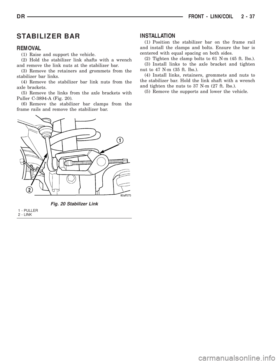
(5) Remove the links from the axle brackets with
Puller C-3894-A (Fig. 20).
(6) Remove the stabilizer bar clamps from the
frame rails and remove the stabilizer bar.
INSTALLATION
(1) Position the stabilizer bar on the frame rail
and install the clamps and bolts. Ensure the bar is
centered with equal spacing on both sides.
(2) Tighten the clamp bolts to 61 N´m (45 ft. lbs.).
(3) Install links to the axle bracket and tighten
nut to 47 N´m (35 ft. lbs.).
(4) Install links, retainers, grommets and nuts to
the stabilizer bar. Hold the link shaft with a wrench
and tighten the nuts to 37 N´m (27 ft. lbs.).
(5) Remove the supports and lower the vehicle.
Fig. 20 Stabilizer Link
1 - PULLER
2 - LINK
DRFRONT - LINK/COIL 2 - 37
Page 122 of 2895

(6) Position upper and lower suspension arms in
the axle brackets. Install bolts, nuts and align the
suspension alignment cams to the reference marks.
Do not tighten at this time.
(7) Connect track bar to the axle bracket and
install the bolt. Do not tighten at this time.
(8) Install shock absorber and tighten bolts to 121
N´m (89 ft. lbs.).
(9) Install stabilizer bar link to the axle bracket.
Tighten the nut to 68 N´m (50 ft. lbs.).
(10) Install drag link and tie rod to the steering
knuckles and tighten the nuts to 108 N´m (80 ft.
lbs.).
(11) Install ABS wheel speed sensors.
(12) Install rotors and brake calipers.
(13) Connect the axle vent hose.
(14) Install front propeller shaft.
(15) Check and add differential lubricant, if neces-
sary.
(16) Install wheel and tire assemblies.
(17) Remove lower the vehicle.
(18) Tighten upper suspension arm nuts at axle to
149 N´m (110 ft. lbs.). Tighten upper suspension arm
nuts at frame to 149 N´m (110 ft. lbs.).
(19) Tighten lower suspension arm nuts at axle to
190 N´m (140 ft. lbs.). Tighten the lower suspension
arm nuts at frame to 190 N´m (140 ft. lbs.).
(20) Tighten track bar bolt at the axle bracket to
176 N´m (130 ft. lbs.).
(21) Check front wheel alignment.
ADJUSTMENTS
Ring and pinion gears are supplied as matched
sets only. Compensation for pinion depth variance is
achieved with a select shim. The shim is located
between the rear pinion bearing and the pinion gear
head.
PINION DEPTH MEASUREMENT AND ADJUSTMENT
Measurements are taken with pinion bearing cups
and pinion bearings installed in the housing. Take
measurements with Pinion Gauge Set and Dial Indi-
cator C-3339 (Fig. 1).
(1) Assemble Pinion Height Block 6739, Pinion
Block 8878 and rear pinion bearing onto Screw 6741
(Fig. 1).
(2) Insert assembled height gauge components,
rear bearing and screw into the housing through pin-
ion bearing cups (Fig. 2).
(3) Install front pinion bearing and install the
Cone-nut 6740 hand tight. Then check tool rotating
torque with an inch pound torque wrench. The rotat-
ing torque should be 1.7-2.26 N´m (15-20 in. lbs.)
(4) Place Arbor Disc 8289 on Arbor D-115-3 in posi-
tion in the housing side bearing cradles (Fig. 3).(5) Install differential bearing caps on arbor discs
and snug the bearing cap bolts. Then cross tighten
cap bolts to 85 N´m (63 ft. lbs.).
Fig. 1 PINION GEAR DEPTH GAUGE TOOLS
1 - DIAL INDICATOR
2 - ARBOR
3 - PINION HEIGHT BLOCK
4 - CONE
5 - SCREW
6 - PINION BLOCK
7 - SCOOTER BLOCK
8 - ARBOR DISC
Fig. 2 PINION HEIGHT BLOCK
1. PINION HEIGHT BLOCK
2. PINION BLOCK
DRFRONT AXLE - 9 1/4 AA 3 - 49
FRONT AXLE - 9 1/4 AA (Continued)
Page 233 of 2895
ADJUSTABLE PEDAL SWITCH
REMOVAL
(1) Remove the lower drivers side bezel (Refer to
23 - BODY/INSTRUMENT PANEL/INSTRUMENT
PANEL DR SIDE BEZEL - REMOVAL).
(2) Disconnect the electrical connector from the
adjustable pedal switch.
(3) Remove the switch from the lower drivers side
bezel by squeezing the retaining clips together and
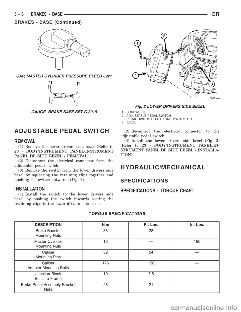
pushing the switch outwards (Fig. 2).
INSTALLATION
(1) Install the switch to the lower drivers side
bezel by pushing the switch inwards seating the
retaining clips to the lower drivers side bezel.(2) Reconnect the electrical connector to the
adjustable pedal switch.
(3) Install the lower drivers side bezel (Fig. 2)
(Refer to 23 - BODY/INSTRUMENT PANEL/IN-
STRUMENT PANEL DR SIDE BEZEL - INSTALLA-
TION).
HYDRAULIC/MECHANICAL
SPECIFICATIONS
SPECIFICATIONS - TORQUE CHART
TORQUE SPECIFICATIONS
DESCRIPTION N´m Ft. Lbs. In. Lbs.
Brake Booster
Mounting Nuts38 28 Ð
Master Cylinder
Mounting Nuts18 Ð 160
Caliper
Mounting Pins32 24 Ð
Caliper
Adapter Mounting Bolts176 130 Ð
Junction Block
Bolts To Frame10 7.5 Ð
Brake Pedal Assembly Bracket
Nuts28 21 Ð
CAP, MASTER CYLINDER PRESSURE BLEED 6921
GAUGE, BRAKE SAFE-SET C-3919
Fig. 2 LOWER DRIVERS SIDE BEZEL
1 - SCREWS (2)
2 - ADJUSTABLE PEDAL SWITCH
3 - PEDAL SWITCH ELECTRICAL CONNECTOR
4 - BEZEL
5 - 6 BRAKES - BASEDR
BRAKES - BASE (Continued)
Page 234 of 2895
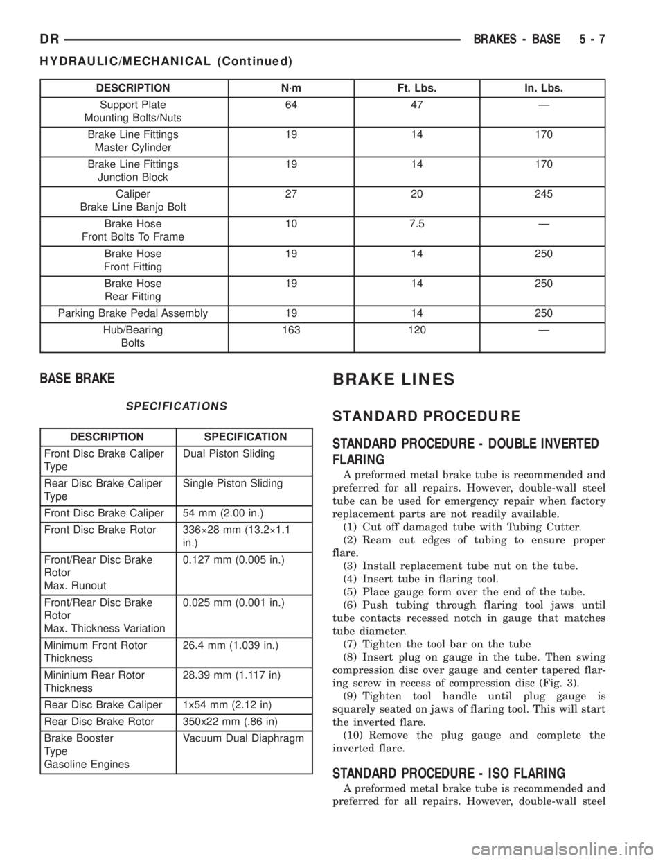
DESCRIPTION N´m Ft. Lbs. In. Lbs.
Support Plate
Mounting Bolts/Nuts64 47 Ð
Brake Line Fittings
Master Cylinder19 14 170
Brake Line Fittings
Junction Block19 14 170
Caliper
Brake Line Banjo Bolt27 20 245
Brake Hose
Front Bolts To Frame10 7.5 Ð
Brake Hose
Front Fitting19 14 250
Brake Hose
Rear Fitting19 14 250
Parking Brake Pedal Assembly 19 14 250
Hub/Bearing
Bolts163 120 Ð
BASE BRAKE
SPECIFICATIONS
DESCRIPTION SPECIFICATION
Front Disc Brake Caliper
TypeDual Piston Sliding
Rear Disc Brake Caliper
TypeSingle Piston Sliding
Front Disc Brake Caliper 54 mm (2.00 in.)
Front Disc Brake Rotor 336ý28 mm (13.2ý1.1
in.)
Front/Rear Disc Brake
Rotor
Max. Runout0.127 mm (0.005 in.)
Front/Rear Disc Brake
Rotor
Max. Thickness Variation0.025 mm (0.001 in.)
Minimum Front Rotor
Thickness26.4 mm (1.039 in.)
Mininium Rear Rotor
Thickness28.39 mm (1.117 in)
Rear Disc Brake Caliper 1x54 mm (2.12 in)
Rear Disc Brake Rotor 350x22 mm (.86 in)
Brake Booster
Type
Gasoline EnginesVacuum Dual Diaphragm
BRAKE LINES
STANDARD PROCEDURE
STANDARD PROCEDURE - DOUBLE INVERTED
FLARING
A preformed metal brake tube is recommended and
preferred for all repairs. However, double-wall steel
tube can be used for emergency repair when factory
replacement parts are not readily available.
(1) Cut off damaged tube with Tubing Cutter.
(2) Ream cut edges of tubing to ensure proper
flare.
(3) Install replacement tube nut on the tube.
(4) Insert tube in flaring tool.
(5) Place gauge form over the end of the tube.
(6) Push tubing through flaring tool jaws until
tube contacts recessed notch in gauge that matches
tube diameter.
(7) Tighten the tool bar on the tube
(8) Insert plug on gauge in the tube. Then swing
compression disc over gauge and center tapered flar-
ing screw in recess of compression disc (Fig. 3).
(9) Tighten tool handle until plug gauge is
squarely seated on jaws of flaring tool. This will start
the inverted flare.
(10) Remove the plug gauge and complete the
inverted flare.
STANDARD PROCEDURE - ISO FLARING
A preformed metal brake tube is recommended and
preferred for all repairs. However, double-wall steel
DRBRAKES - BASE 5 - 7
HYDRAULIC/MECHANICAL (Continued)
Page 235 of 2895
tube can be used for emergency repair when factory
replacement parts are not readily available.
To make a ISO flare use an ISO flaring tool kit.
(1) Cut off damaged tube with Tubing Cutter.
(2) Remove any burrs from the inside of the tube.
(3) Install tube nut on the tube.
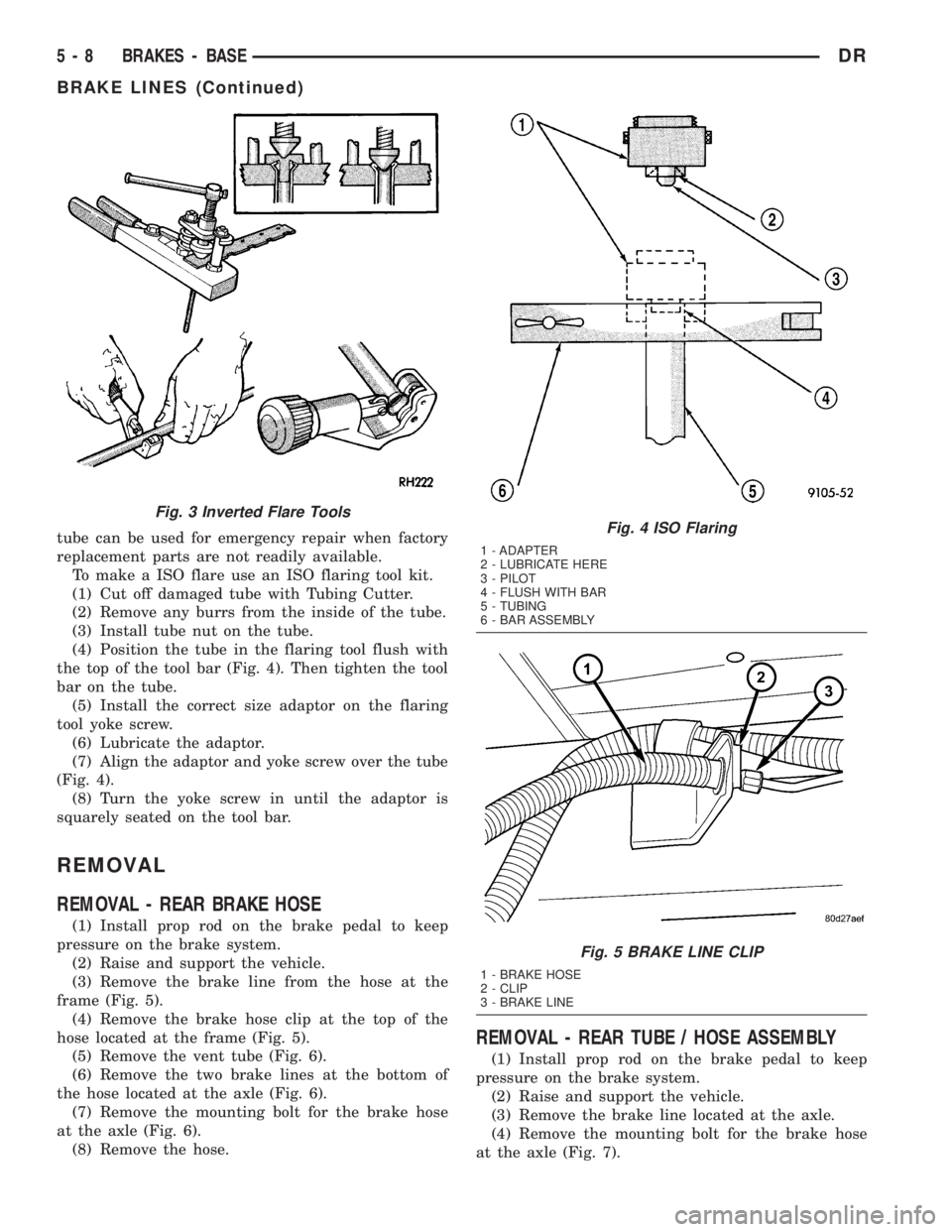
(4) Position the tube in the flaring tool flush with
the top of the tool bar (Fig. 4). Then tighten the tool
bar on the tube.
(5) Install the correct size adaptor on the flaring
tool yoke screw.
(6) Lubricate the adaptor.
(7) Align the adaptor and yoke screw over the tube
(Fig. 4).
(8) Turn the yoke screw in until the adaptor is
squarely seated on the tool bar.
REMOVAL
REMOVAL - REAR BRAKE HOSE
(1) Install prop rod on the brake pedal to keep
pressure on the brake system.
(2) Raise and support the vehicle.
(3) Remove the brake line from the hose at the
frame (Fig. 5).
(4) Remove the brake hose clip at the top of the
hose located at the frame (Fig. 5).
(5) Remove the vent tube (Fig. 6).
(6) Remove the two brake lines at the bottom of
the hose located at the axle (Fig. 6).
(7) Remove the mounting bolt for the brake hose
at the axle (Fig. 6).
(8) Remove the hose.
REMOVAL - REAR TUBE / HOSE ASSEMBLY
(1) Install prop rod on the brake pedal to keep
pressure on the brake system.
(2) Raise and support the vehicle.
(3) Remove the brake line located at the axle.
(4) Remove the mounting bolt for the brake hose
at the axle (Fig. 7).
Fig. 3 Inverted Flare Tools
Fig. 4 ISO Flaring
1 - ADAPTER
2 - LUBRICATE HERE
3 - PILOT
4 - FLUSH WITH BAR
5 - TUBING
6 - BAR ASSEMBLY
Fig. 5 BRAKE LINE CLIP
1 - BRAKE HOSE
2 - CLIP
3 - BRAKE LINE
5 - 8 BRAKES - BASEDR
BRAKE LINES (Continued)
Page 236 of 2895

(5) Remove the banjo bolt at the caliper (Fig. 7).
(6) Remove the hose.
REMOVAL - FRONT HOSE
(1) Install a prop rod on the brake pedal to keep
pressure on the brake system.
(2) Raise and support vehicle.
(3) Remove the tire and wheel assembly.
(4) Remove the brake hose from the brake line
located at the frame (Fig. 8).
(5) Remove the brake hose banjo bolt at the caliper
(Fig. 8).
(6) Remove the mounting bolt securing the brake
hose to the frame and remove the wheel speed sensor
wire from the brake hose (Fig. 8).
(7) Remove the hose.
INSTALLATION
INSTALLATION - REAR BRAKE HOSE
(1) Install the hose.
(2) Install the mounting bolt for the brake hose at
the axle (Fig. 6).
(3) Install the two brake lines at the bottom of the
hose located at the axle (Fig. 6).
(4) Install the vent tube (Fig. 6).
(5) Install the brake hose clip at the top of the
hose located at the frame (Fig. 5).
(6) Install the brake line to the hose at the frame
(Fig. 5).
(7) Lower the vehicle and remove the support.
(8) Remove the prop rod.
(9) Bleed the brake system (Refer to 5 - BRAKES -
STANDARD PROCEDURE).
INSTALLATION - REAR TUBE / HOSE
ASSEMBLY
(1) Install the hose.
(2) Install the banjo bolt at the caliper (Fig. 7).
(3) Install the mounting bolt for the brake hose at
the axle (Fig. 7).
(4) Install the brake line located at the axle.
(5) Lower the vehicle and remove the support.
(6) Remove the prop rod.
(7) Bleed the brake system (Refer to 5 - BRAKES -
STANDARD PROCEDURE).
INSTALLATION - FRONT BRAKE HOSE
(1) Install the hose.
(2) Install the mounting bolt for the brake hose at
the frame (Fig. 9).
Fig. 6 REAR HOSE
1 - BRAKE HOSE
2 - VENT HOSE
3 - BRAKE LINES
Fig. 7 BRAKE LINE WITH RUBBER HOSE
1 - BANJO BOLT
2 - MOUNTING BOLT
3 - REAR TUBE / HOSE ASSEMBLY
Fig. 8 BRAKE HOSE MOUNTED PASSENGER SIDE
1 - MOUNTING BOLT
2 - BRAKE HOSE
3 - BANJO BOLT
4 - WHEEL SPEED SENSOR WIRE
DRBRAKES - BASE 5 - 9
BRAKE LINES (Continued)
Page 258 of 2895
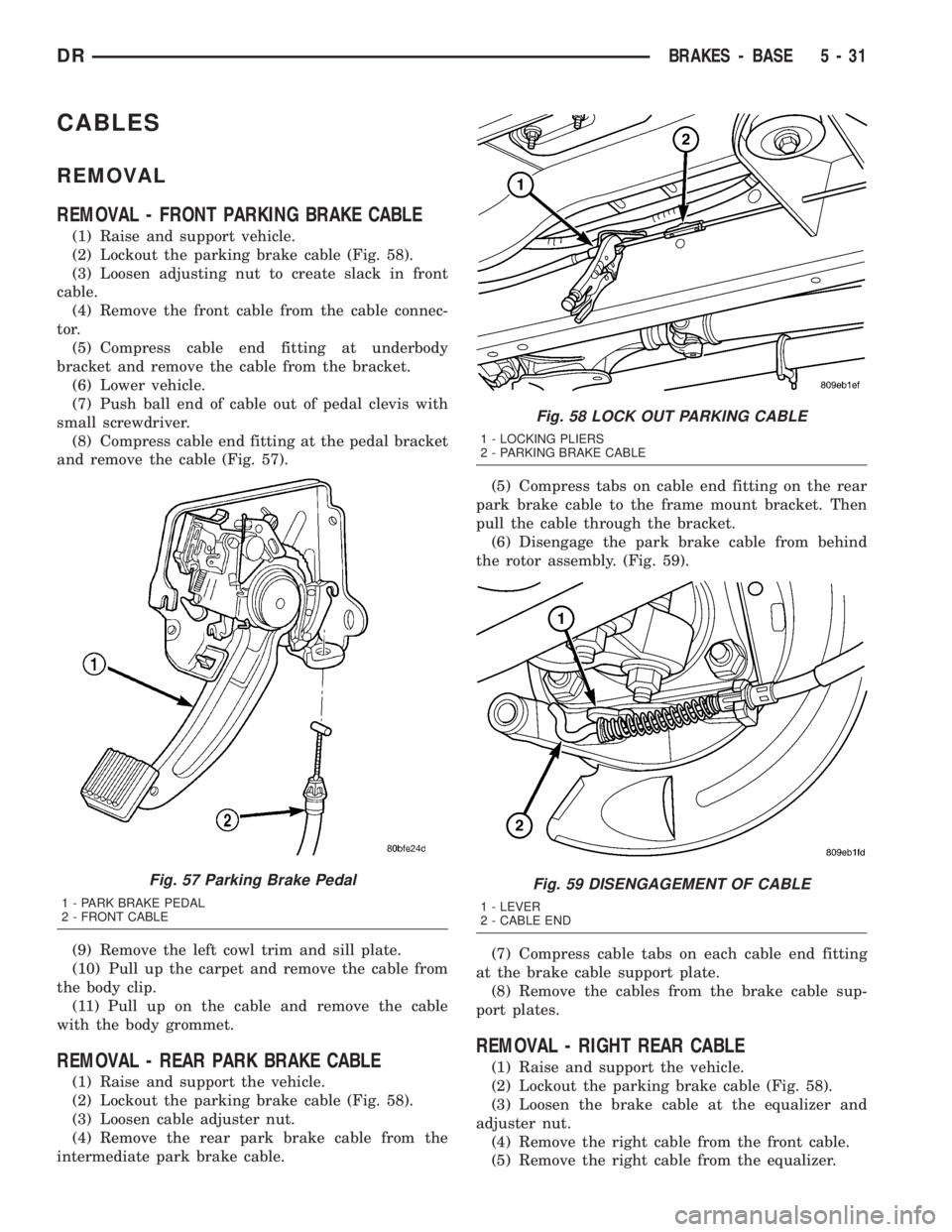
CABLES
REMOVAL
REMOVAL - FRONT PARKING BRAKE CABLE
(1) Raise and support vehicle.
(2) Lockout the parking brake cable (Fig. 58).
(3) Loosen adjusting nut to create slack in front
cable.
(4) Remove the front cable from the cable connec-
tor.
(5) Compress cable end fitting at underbody
bracket and remove the cable from the bracket.
(6) Lower vehicle.
(7) Push ball end of cable out of pedal clevis with
small screwdriver.
(8) Compress cable end fitting at the pedal bracket
and remove the cable (Fig. 57).
(9) Remove the left cowl trim and sill plate.
(10) Pull up the carpet and remove the cable from
the body clip.
(11) Pull up on the cable and remove the cable
with the body grommet.
REMOVAL - REAR PARK BRAKE CABLE
(1) Raise and support the vehicle.
(2) Lockout the parking brake cable (Fig. 58).
(3) Loosen cable adjuster nut.
(4) Remove the rear park brake cable from the
intermediate park brake cable.(5) Compress tabs on cable end fitting on the rear
park brake cable to the frame mount bracket. Then
pull the cable through the bracket.
(6) Disengage the park brake cable from behind
the rotor assembly. (Fig. 59).
(7) Compress cable tabs on each cable end fitting
at the brake cable support plate.
(8) Remove the cables from the brake cable sup-
port plates.
REMOVAL - RIGHT REAR CABLE
(1) Raise and support the vehicle.
(2) Lockout the parking brake cable (Fig. 58).
(3) Loosen the brake cable at the equalizer and
adjuster nut.
(4) Remove the right cable from the front cable.
(5) Remove the right cable from the equalizer.
Fig. 57 Parking Brake Pedal
1 - PARK BRAKE PEDAL
2 - FRONT CABLE
Fig. 58 LOCK OUT PARKING CABLE
1 - LOCKING PLIERS
2 - PARKING BRAKE CABLE
Fig. 59 DISENGAGEMENT OF CABLE
1 - LEVER
2 - CABLE END
DRBRAKES - BASE 5 - 31
Page 259 of 2895
(6) Remove the cable from the frame bracket.
(7) Remove the cable from the axle bracket.
(8) Remove the cable bracket from the shock
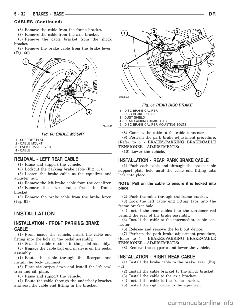
bracket.
(9) Remove the brake cable from the brake lever.
(Fig. 60)
REMOVAL - LEFT REAR CABLE
(1) Raise and support the vehicle.
(2) Lockout the parking brake cable (Fig. 58).
(3) Loosen the brake cable at the equalizer and
adjuster nut.
(4) Remove the left brake cable from the equalizer.
(5) Remove the brake cable from the frame
bracket.
(6) Remove the brake cable from the brake lever.
(Fig. 61)
INSTALLATION
INSTALLATION - FRONT PARKING BRAKE
CABLE
(1) From inside the vehicle, insert the cable end
fitting into the hole in the pedal assembly.
(2) Seat the cable retainer in the pedal assembly.
(3) Engage the cable ball end in clevis on the pedal
assembly.
(4) Route the cable through the floorpan and
install the body grommet.
(5) Place the carpet down and install the left cowl
trim and sill plate.
(6) Raise and support the vehicle.
(7) Route the cable through the underbody bracket
and seat the cable end fitting in the bracket.(8) Connect the cable to the cable connector.
(9) Perform the park brake adjustment procedure,
(Refer to 5 - BRAKES/PARKING BRAKE/CABLE
TENSIONER - ADJUSTMENTS).
(10) Lower the vehicle.
INSTALLATION - REAR PARK BRAKE CABLE
(1) Push each cable end through the brake cable
support plate hole until the cable end fitting tabs
lock into place.
NOTE: Pull on the cable to ensure it is locked into
place.
(2) Push the cable through the frame bracket.
(3) Lock the left cable end fitting tabs into the
frame bracket hole.
(4) Install the rear cables into the tensioner rod
behind the rear of the brake assembly.
(5) Install the cable to the intermediate cable con-
nector.
(6) Release and remove the lock out device.
(7) Perform the park brake adjustment procedure,
(Refer to 5 - BRAKES/PARKING BRAKE/CABLE
TENSIONER - ADJUSTMENTS).
(8) Remove the supports and lower the vehicle.
INSTALLATION - RIGHT REAR CABLE
(1) Install the brake cable to the brake lever. (Fig.
62)
(2) Install the cable bracket to the shock bracket.
(3) Install the cable to the axle bracket.
(4) Install the cable to the frame bracket.
(5) Install the right cable to the equalizer.
Fig. 60 CABLE MOUNT
1 - SUPPORT PLAT
2 - CABLE MOUNT
3 - PARK BRAKE LEVER
4 - CABLE
Fig. 61 REAR DISC BRAKE
1 - DISC BRAKE CALIPER
2 - DISC BRAKE ROTOR
3 - DUST SHIELD
4 - REAR PARKING BRAKE CABLE
5 - DISC BRAKE CALIPER MOUNTING BOLTS
5 - 32 BRAKES - BASEDR
CABLES (Continued)