2003 DODGE RAM frame
[x] Cancel search: framePage 1315 of 2895

INSPECTION
(1) Inspect oil drain plug and plug hole for
stripped or damaged threads. Repair as necessary.
(2) Inspect the oil pan mounting flange for bends
or distortion. Straighten flange, if necessary.
INSTALLATION
(1) Clean the oil pan gasket mating surface of the
bedplate and oil pan.
(2) Inspect integrated oil pan gasket, and replace
as necessary.
(3) Position the integrated oil pan gasket/windage
tray assembly.
(4) Install the oil pickup tube
(5) Install the mounting bolt and nuts. Tighten
nuts to 28 N´m (20 ft. lbs.).
(6) Position the oil pan and install the mounting
bolts. Tighten the mounting bolts to 15 N´m (11 ft.
lbs.) in the sequence shown (Fig. 75).
(7) Lower the engine into mounts using special
tool # 8534.
(8) Install both the left and right side engine
mount through bolts. Tighten the nuts to 68 N´m (50
ft. lbs.).
(9) Remove special tool # 8534.
(10) Install structural dust cover, if equipped.
(11) Install the front crossmember(Refer to 13 -
FRAME & BUMPERS/FRAME/FRONT CROSS-
MEMBER - INSTALLATION).
(12) Fill engine oil.
(13) Reconnect the negative battery cable.
(14) Start engine and check for leaks.
OIL PRESSURE SENSOR/
SWITCH
DESCRIPTION
The 3±wire, solid-state engine oil pressure sensor
(sending unit) is located in an engine oil pressure
gallery.
OPERATION
The oil pressure sensor uses three circuits. They
are:²A 5±volt power supply from the Powertrain Con-
trol Module (PCM)
²A sensor ground through the PCM's sensor
return
²A signal to the PCM relating to engine oil pres-
sure
The oil pressure sensor has a 3±wire electrical
function very much like the Manifold Absolute Pres-
sure (MAP) sensor. Meaning different pressures
relate to different output voltages.
A 5±volt supply is sent to the sensor from the PCM
to power up the sensor. The sensor returns a voltage
signal back to the PCM relating to engine oil pres-
sure. This signal is then transferred (bussed) to the
instrument panel on either a CCD or PCI bus circuit
(depending on vehicle line) to operate the oil pressure
gauge and the check gauges lamp. Ground for the
sensor is provided by the PCM through a low-noise
sensor return.
Fig. 75 Oil Pan Mounting Bolt Sequence
9 - 66 ENGINE - 3.7LDR
OIL PAN (Continued)
Page 1393 of 2895
(3) Install the four cover-to-transmission bolts. Do
NOT tighten at this time.
CAUTION: The structural cover must be held tightly
against both the engine and the transmission bell
housing during tightening sequence. Failure to do
so may cause damage to the cover.
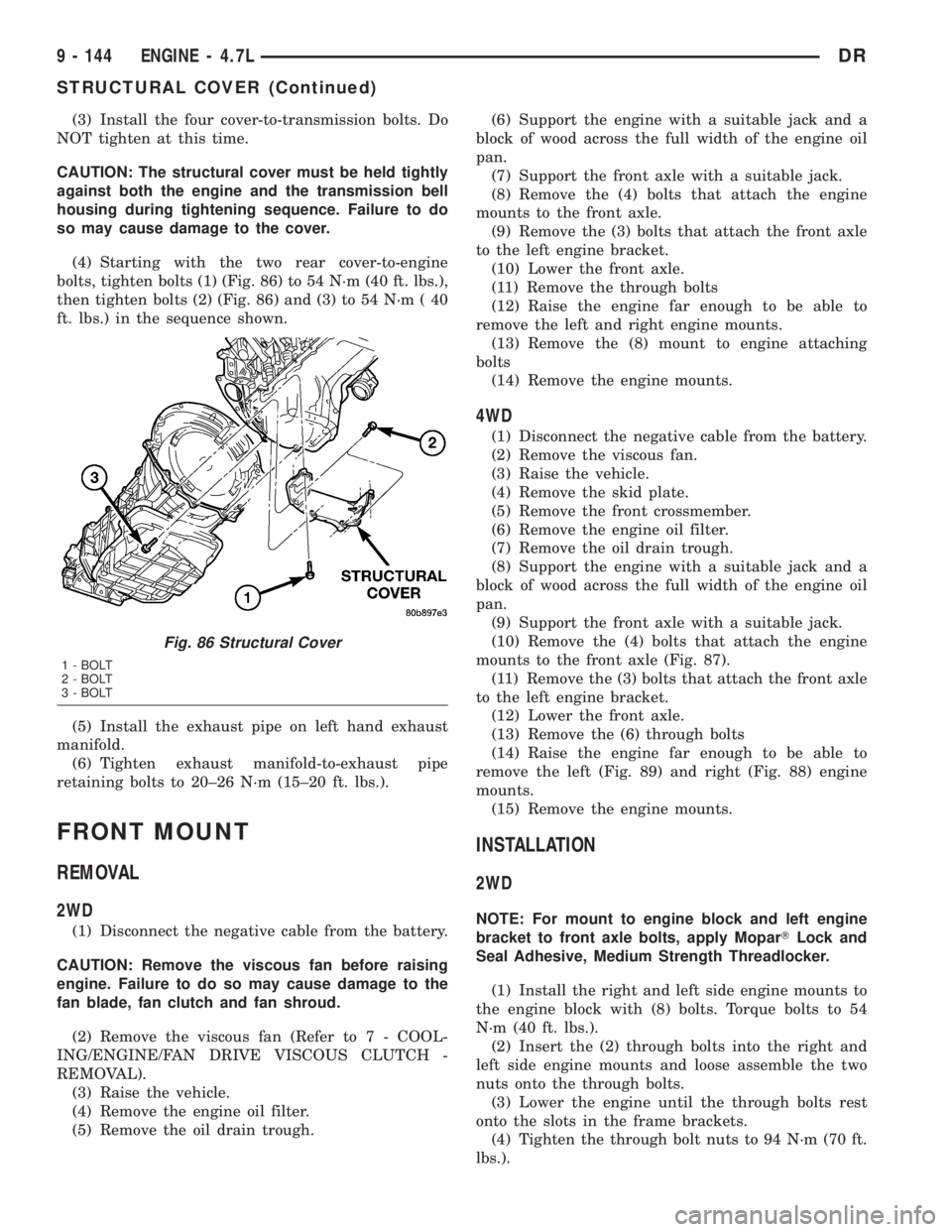
(4) Starting with the two rear cover-to-engine
bolts, tighten bolts (1) (Fig. 86) to 54 N´m (40 ft. lbs.),
then tighten bolts (2) (Fig. 86) and (3) to 54 N´m ( 40
ft. lbs.) in the sequence shown.
(5) Install the exhaust pipe on left hand exhaust
manifold.
(6) Tighten exhaust manifold-to-exhaust pipe
retaining bolts to 20±26 N´m (15±20 ft. lbs.).
FRONT MOUNT
REMOVAL
2WD
(1) Disconnect the negative cable from the battery.
CAUTION: Remove the viscous fan before raising
engine. Failure to do so may cause damage to the
fan blade, fan clutch and fan shroud.
(2) Remove the viscous fan (Refer to 7 - COOL-
ING/ENGINE/FAN DRIVE VISCOUS CLUTCH -
REMOVAL).
(3) Raise the vehicle.
(4) Remove the engine oil filter.
(5) Remove the oil drain trough.(6) Support the engine with a suitable jack and a
block of wood across the full width of the engine oil
pan.
(7) Support the front axle with a suitable jack.
(8) Remove the (4) bolts that attach the engine
mounts to the front axle.
(9) Remove the (3) bolts that attach the front axle
to the left engine bracket.
(10) Lower the front axle.
(11) Remove the through bolts
(12) Raise the engine far enough to be able to
remove the left and right engine mounts.
(13) Remove the (8) mount to engine attaching
bolts
(14) Remove the engine mounts.
4WD
(1) Disconnect the negative cable from the battery.
(2) Remove the viscous fan.
(3) Raise the vehicle.
(4) Remove the skid plate.
(5) Remove the front crossmember.
(6) Remove the engine oil filter.
(7) Remove the oil drain trough.
(8) Support the engine with a suitable jack and a
block of wood across the full width of the engine oil
pan.
(9) Support the front axle with a suitable jack.
(10) Remove the (4) bolts that attach the engine
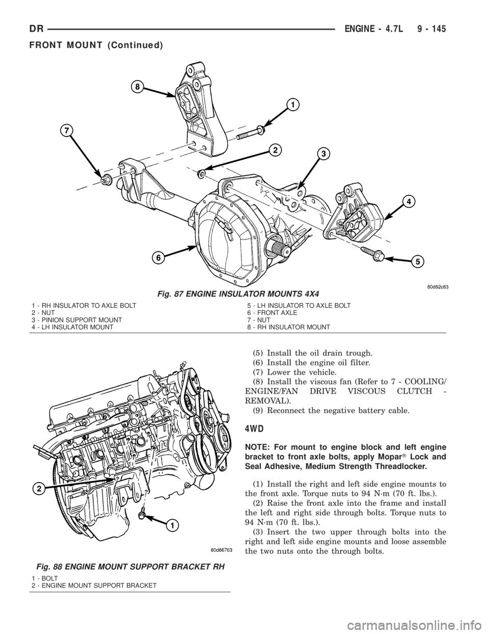
mounts to the front axle (Fig. 87).
(11) Remove the (3) bolts that attach the front axle
to the left engine bracket.
(12) Lower the front axle.
(13) Remove the (6) through bolts
(14) Raise the engine far enough to be able to
remove the left (Fig. 89) and right (Fig. 88) engine
mounts.
(15) Remove the engine mounts.
INSTALLATION
2WD
NOTE: For mount to engine block and left engine
bracket to front axle bolts, apply MoparTLock and
Seal Adhesive, Medium Strength Threadlocker.
(1) Install the right and left side engine mounts to
the engine block with (8) bolts. Torque bolts to 54
N´m (40 ft. lbs.).
(2) Insert the (2) through bolts into the right and
left side engine mounts and loose assemble the two
nuts onto the through bolts.
(3) Lower the engine until the through bolts rest
onto the slots in the frame brackets.
(4) Tighten the through bolt nuts to 94 N´m (70 ft.
lbs.).
Fig. 86 Structural Cover
1 - BOLT
2 - BOLT
3 - BOLT
9 - 144 ENGINE - 4.7LDR
STRUCTURAL COVER (Continued)
Page 1394 of 2895
(5) Install the oil drain trough.
(6) Install the engine oil filter.
(7) Lower the vehicle.
(8) Install the viscous fan (Refer to 7 - COOLING/
ENGINE/FAN DRIVE VISCOUS CLUTCH -
REMOVAL).
(9) Reconnect the negative battery cable.
4WD
NOTE: For mount to engine block and left engine
bracket to front axle bolts, apply MoparTLock and
Seal Adhesive, Medium Strength Threadlocker.
(1) Install the right and left side engine mounts to
the front axle. Torque nuts to 94 N´m (70 ft. lbs.).
(2) Raise the front axle into the frame and install
the left and right side through bolts. Torque nuts to
94 N´m (70 ft. lbs.).
(3) Insert the two upper through bolts into the
right and left side engine mounts and loose assemble
the two nuts onto the through bolts.
Fig. 87 ENGINE INSULATOR MOUNTS 4X4
1 - RH INSULATOR TO AXLE BOLT
2 - NUT
3 - PINION SUPPORT MOUNT
4 - LH INSULATOR MOUNT5 - LH INSULATOR TO AXLE BOLT
6 - FRONT AXLE
7 - NUT
8 - RH INSULATOR MOUNT
Fig. 88 ENGINE MOUNT SUPPORT BRACKET RH
1 - BOLT
2 - ENGINE MOUNT SUPPORT BRACKET
DRENGINE - 4.7L 9 - 145
FRONT MOUNT (Continued)
Page 1402 of 2895
(4) When filter separates from cylinder block oil
filter boss, tip gasket end upward to minimize oil
spill. Remove filter from vehicle.
NOTE: Make sure filter gasket was removed with fil-
ter.
(5) With a wiping cloth, clean the gasket sealing
surface of oil and grime.
INSTALLATION
(1) Lightly lubricate oil filter gasket with engine
oil.
(2) Thread filter onto adapter nipple. When gasket
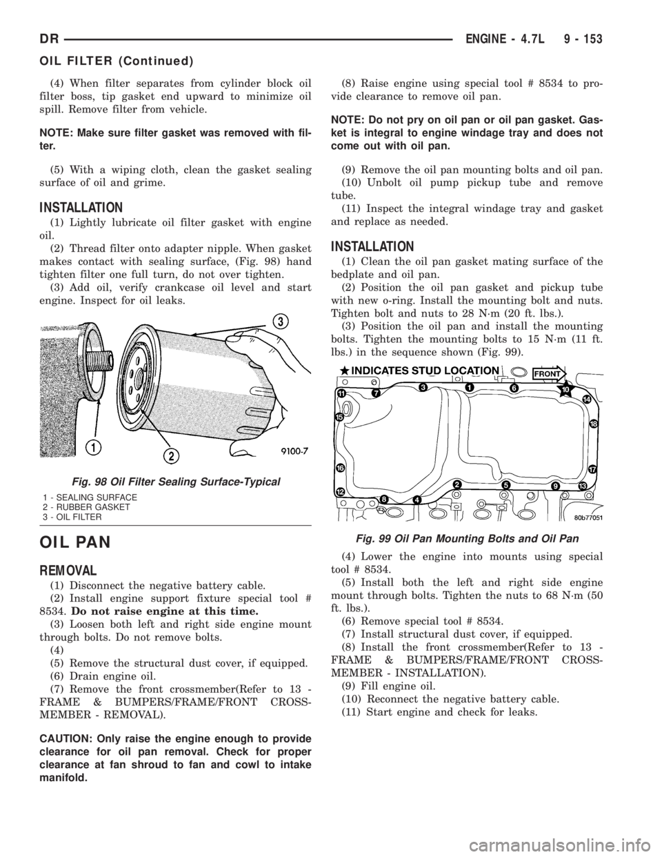
makes contact with sealing surface, (Fig. 98) hand
tighten filter one full turn, do not over tighten.
(3) Add oil, verify crankcase oil level and start
engine. Inspect for oil leaks.
OIL PAN
REMOVAL
(1) Disconnect the negative battery cable.
(2) Install engine support fixture special tool #
8534.Do not raise engine at this time.
(3) Loosen both left and right side engine mount
through bolts. Do not remove bolts.
(4)
(5) Remove the structural dust cover, if equipped.
(6) Drain engine oil.
(7) Remove the front crossmember(Refer to 13 -
FRAME & BUMPERS/FRAME/FRONT CROSS-
MEMBER - REMOVAL).
CAUTION: Only raise the engine enough to provide
clearance for oil pan removal. Check for proper
clearance at fan shroud to fan and cowl to intake
manifold.(8) Raise engine using special tool # 8534 to pro-
vide clearance to remove oil pan.
NOTE: Do not pry on oil pan or oil pan gasket. Gas-
ket is integral to engine windage tray and does not
come out with oil pan.
(9) Remove the oil pan mounting bolts and oil pan.
(10) Unbolt oil pump pickup tube and remove
tube.
(11) Inspect the integral windage tray and gasket
and replace as needed.
INSTALLATION
(1) Clean the oil pan gasket mating surface of the
bedplate and oil pan.
(2) Position the oil pan gasket and pickup tube
with new o-ring. Install the mounting bolt and nuts.
Tighten bolt and nuts to 28 N´m (20 ft. lbs.).
(3) Position the oil pan and install the mounting
bolts. Tighten the mounting bolts to 15 N´m (11 ft.
lbs.) in the sequence shown (Fig. 99).
(4) Lower the engine into mounts using special
tool # 8534.
(5) Install both the left and right side engine
mount through bolts. Tighten the nuts to 68 N´m (50
ft. lbs.).
(6) Remove special tool # 8534.
(7) Install structural dust cover, if equipped.
(8) Install the front crossmember(Refer to 13 -
FRAME & BUMPERS/FRAME/FRONT CROSS-
MEMBER - INSTALLATION).
(9) Fill engine oil.
(10) Reconnect the negative battery cable.
(11) Start engine and check for leaks.
Fig. 98 Oil Filter Sealing Surface-Typical
1 - SEALING SURFACE
2 - RUBBER GASKET
3 - OIL FILTER
Fig. 99 Oil Pan Mounting Bolts and Oil Pan
DRENGINE - 4.7L 9 - 153
OIL FILTER (Continued)
Page 1460 of 2895
FRONT MOUNT
REMOVAL
2WD
(1) Disconnect negative battery cable.
(2) Raise vehicle.
(3) Remove engine mount through bolts.
(4) Raise engine using engine support fixture spe-
cial tool # 8534.
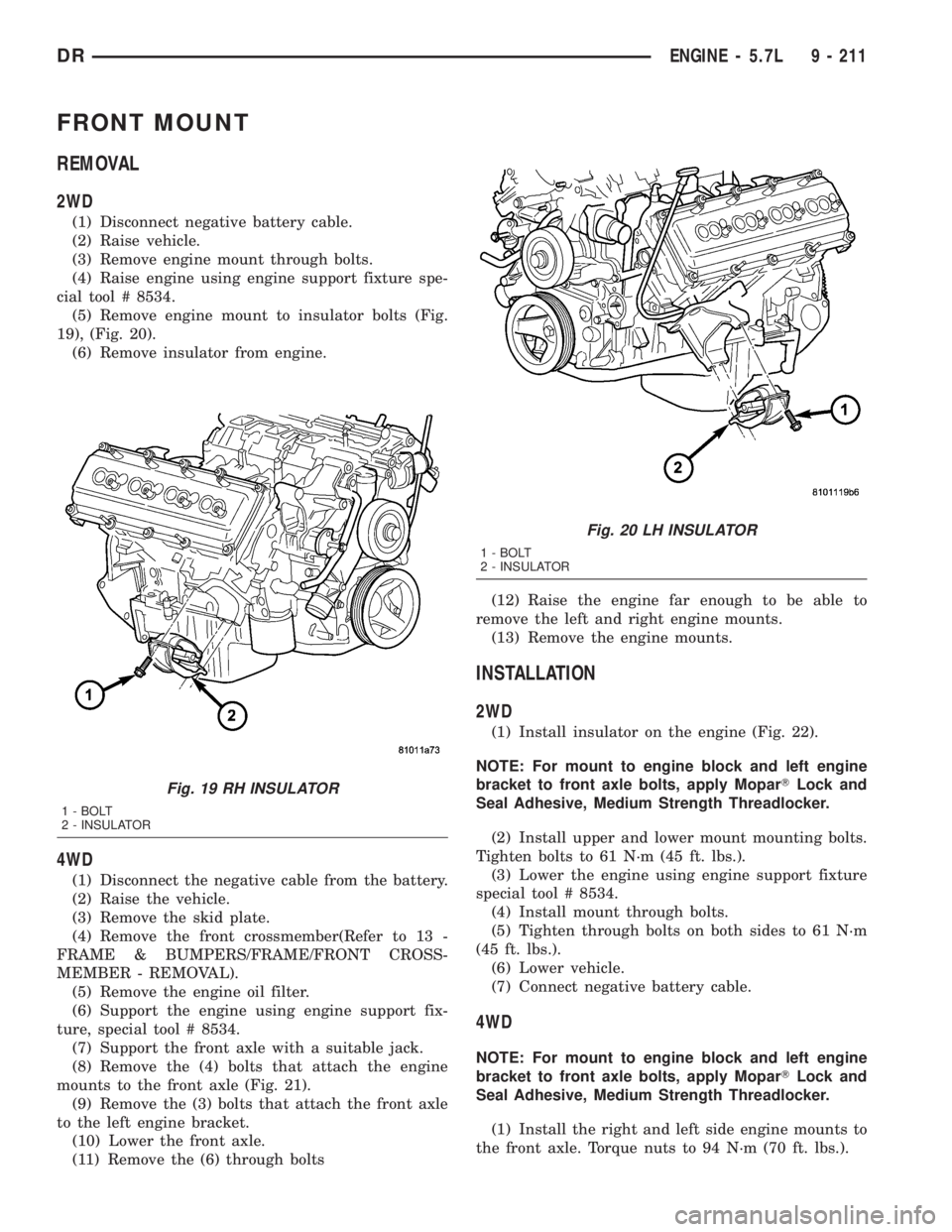
(5) Remove engine mount to insulator bolts (Fig.
19), (Fig. 20).
(6) Remove insulator from engine.
4WD
(1) Disconnect the negative cable from the battery.
(2) Raise the vehicle.
(3) Remove the skid plate.
(4) Remove the front crossmember(Refer to 13 -
FRAME & BUMPERS/FRAME/FRONT CROSS-
MEMBER - REMOVAL).
(5) Remove the engine oil filter.
(6) Support the engine using engine support fix-
ture, special tool # 8534.
(7) Support the front axle with a suitable jack.
(8) Remove the (4) bolts that attach the engine
mounts to the front axle (Fig. 21).
(9) Remove the (3) bolts that attach the front axle
to the left engine bracket.
(10) Lower the front axle.
(11) Remove the (6) through bolts(12) Raise the engine far enough to be able to
remove the left and right engine mounts.
(13) Remove the engine mounts.
INSTALLATION
2WD
(1) Install insulator on the engine (Fig. 22).
NOTE: For mount to engine block and left engine
bracket to front axle bolts, apply MoparTLock and
Seal Adhesive, Medium Strength Threadlocker.
(2) Install upper and lower mount mounting bolts.
Tighten bolts to 61 N´m (45 ft. lbs.).
(3) Lower the engine using engine support fixture
special tool # 8534.
(4) Install mount through bolts.
(5) Tighten through bolts on both sides to 61 N´m
(45 ft. lbs.).
(6) Lower vehicle.
(7) Connect negative battery cable.
4WD
NOTE: For mount to engine block and left engine
bracket to front axle bolts, apply MoparTLock and
Seal Adhesive, Medium Strength Threadlocker.
(1) Install the right and left side engine mounts to
the front axle. Torque nuts to 94 N´m (70 ft. lbs.).
Fig. 19 RH INSULATOR
1 - BOLT
2 - INSULATOR
Fig. 20 LH INSULATOR
1 - BOLT
2 - INSULATOR
DRENGINE - 5.7L 9 - 211
Page 1461 of 2895
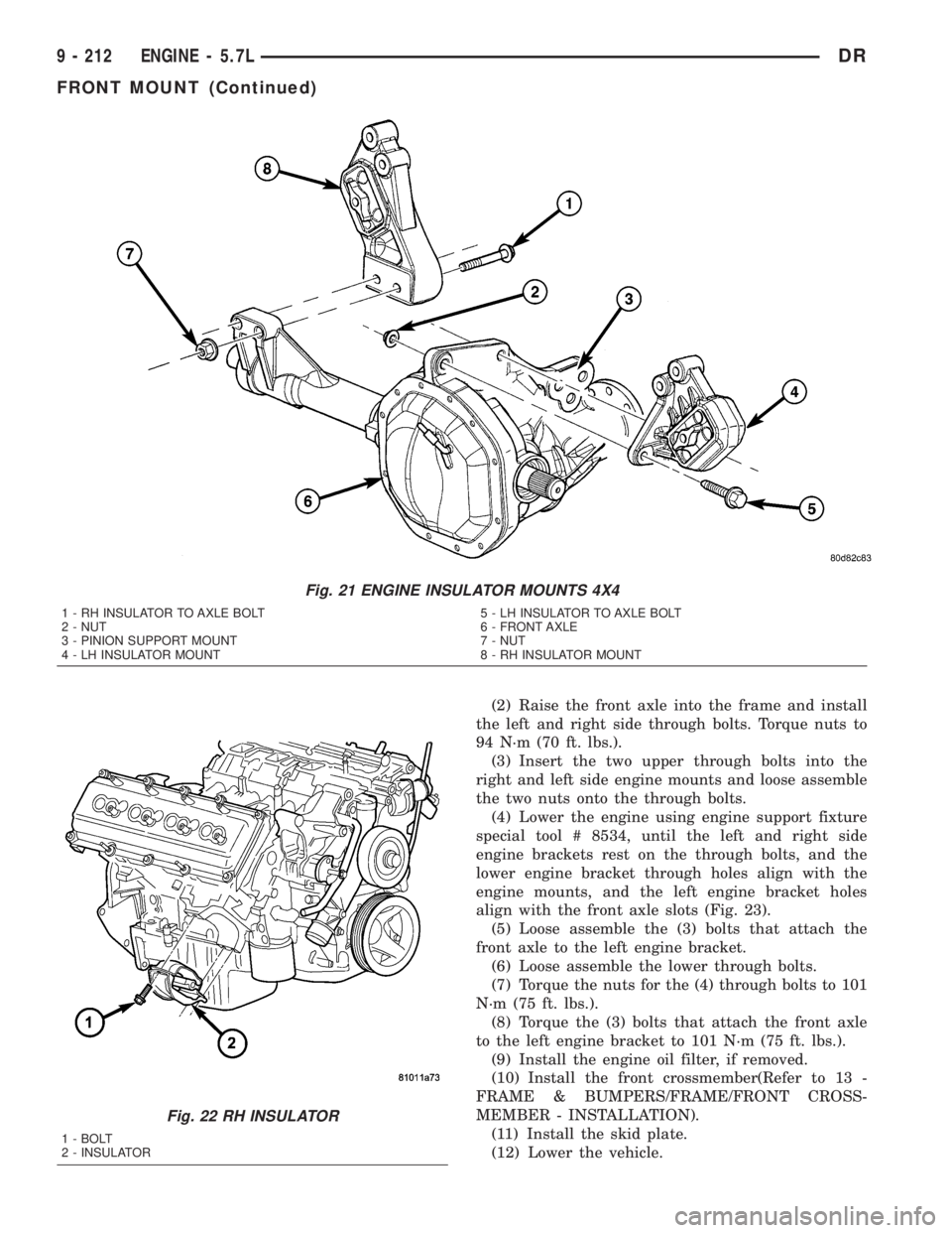
(2) Raise the front axle into the frame and install
the left and right side through bolts. Torque nuts to
94 N´m (70 ft. lbs.).
(3) Insert the two upper through bolts into the
right and left side engine mounts and loose assemble
the two nuts onto the through bolts.
(4) Lower the engine using engine support fixture
special tool # 8534, until the left and right side
engine brackets rest on the through bolts, and the
lower engine bracket through holes align with the
engine mounts, and the left engine bracket holes
align with the front axle slots (Fig. 23).
(5) Loose assemble the (3) bolts that attach the
front axle to the left engine bracket.
(6) Loose assemble the lower through bolts.
(7) Torque the nuts for the (4) through bolts to 101
N´m (75 ft. lbs.).
(8) Torque the (3) bolts that attach the front axle
to the left engine bracket to 101 N´m (75 ft. lbs.).
(9) Install the engine oil filter, if removed.
(10) Install the front crossmember(Refer to 13 -
FRAME & BUMPERS/FRAME/FRONT CROSS-
MEMBER - INSTALLATION).
(11) Install the skid plate.
(12) Lower the vehicle.
Fig. 21 ENGINE INSULATOR MOUNTS 4X4
1 - RH INSULATOR TO AXLE BOLT
2 - NUT
3 - PINION SUPPORT MOUNT
4 - LH INSULATOR MOUNT5 - LH INSULATOR TO AXLE BOLT
6 - FRONT AXLE
7 - NUT
8 - RH INSULATOR MOUNT
Fig. 22 RH INSULATOR
1 - BOLT
2 - INSULATOR
9 - 212 ENGINE - 5.7LDR
FRONT MOUNT (Continued)
Page 1466 of 2895
poration recommends a Mopartor equivalent oil
filter be used.
(1) Position a drain pan under the oil filter.
(2) Using a suitable oil filter wrench loosen filter.
(3) Rotate the oil filter counterclockwise to remove
it from the cylinder block oil filter boss.
(4) When filter separates from cylinder block oil
filter boss, tip gasket end upward to minimize oil
spill. Remove filter from vehicle.
NOTE: Make sure filter gasket was removed with fil-
ter.
(5) With a wiping cloth, clean the gasket sealing
surface of oil and grime.
INSTALLATION
(1) Lightly lubricate oil filter gasket with engine
oil.
(2) Thread filter onto adapter nipple. When gasket
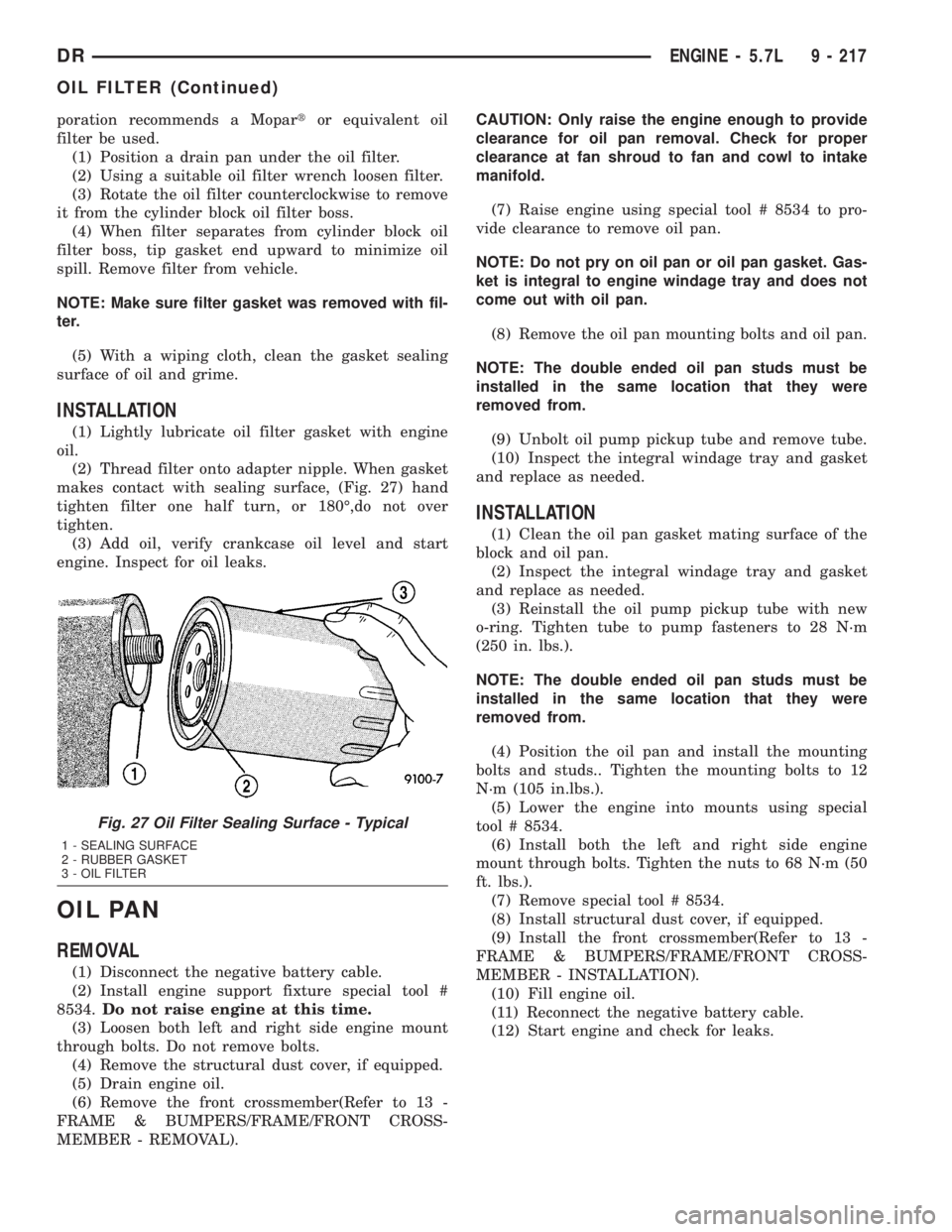
makes contact with sealing surface, (Fig. 27) hand
tighten filter one half turn, or 180É,do not over
tighten.
(3) Add oil, verify crankcase oil level and start
engine. Inspect for oil leaks.
OIL PAN
REMOVAL
(1) Disconnect the negative battery cable.
(2) Install engine support fixture special tool #
8534.Do not raise engine at this time.
(3) Loosen both left and right side engine mount
through bolts. Do not remove bolts.
(4) Remove the structural dust cover, if equipped.
(5) Drain engine oil.
(6) Remove the front crossmember(Refer to 13 -
FRAME & BUMPERS/FRAME/FRONT CROSS-
MEMBER - REMOVAL).CAUTION: Only raise the engine enough to provide
clearance for oil pan removal. Check for proper
clearance at fan shroud to fan and cowl to intake
manifold.
(7) Raise engine using special tool # 8534 to pro-
vide clearance to remove oil pan.
NOTE: Do not pry on oil pan or oil pan gasket. Gas-
ket is integral to engine windage tray and does not
come out with oil pan.
(8) Remove the oil pan mounting bolts and oil pan.
NOTE: The double ended oil pan studs must be
installed in the same location that they were
removed from.
(9) Unbolt oil pump pickup tube and remove tube.
(10) Inspect the integral windage tray and gasket
and replace as needed.
INSTALLATION
(1) Clean the oil pan gasket mating surface of the
block and oil pan.
(2) Inspect the integral windage tray and gasket
and replace as needed.
(3) Reinstall the oil pump pickup tube with new
o-ring. Tighten tube to pump fasteners to 28 N´m
(250 in. lbs.).
NOTE: The double ended oil pan studs must be
installed in the same location that they were
removed from.
(4) Position the oil pan and install the mounting
bolts and studs.. Tighten the mounting bolts to 12
N´m (105 in.lbs.).
(5) Lower the engine into mounts using special
tool # 8534.
(6) Install both the left and right side engine
mount through bolts. Tighten the nuts to 68 N´m (50
ft. lbs.).
(7) Remove special tool # 8534.
(8) Install structural dust cover, if equipped.
(9) Install the front crossmember(Refer to 13 -
FRAME & BUMPERS/FRAME/FRONT CROSS-
MEMBER - INSTALLATION).
(10) Fill engine oil.
(11) Reconnect the negative battery cable.
(12) Start engine and check for leaks.
Fig. 27 Oil Filter Sealing Surface - Typical
1 - SEALING SURFACE
2 - RUBBER GASKET
3 - OIL FILTER
DRENGINE - 5.7L 9 - 217
OIL FILTER (Continued)
Page 1514 of 2895
(11) Remove the (3) bolts that attach the front axle
to the left engine bracket.
(12) Lower the front axle.
(13) Remove the (6) through bolts
(14) Raise the engine far enough to be able to
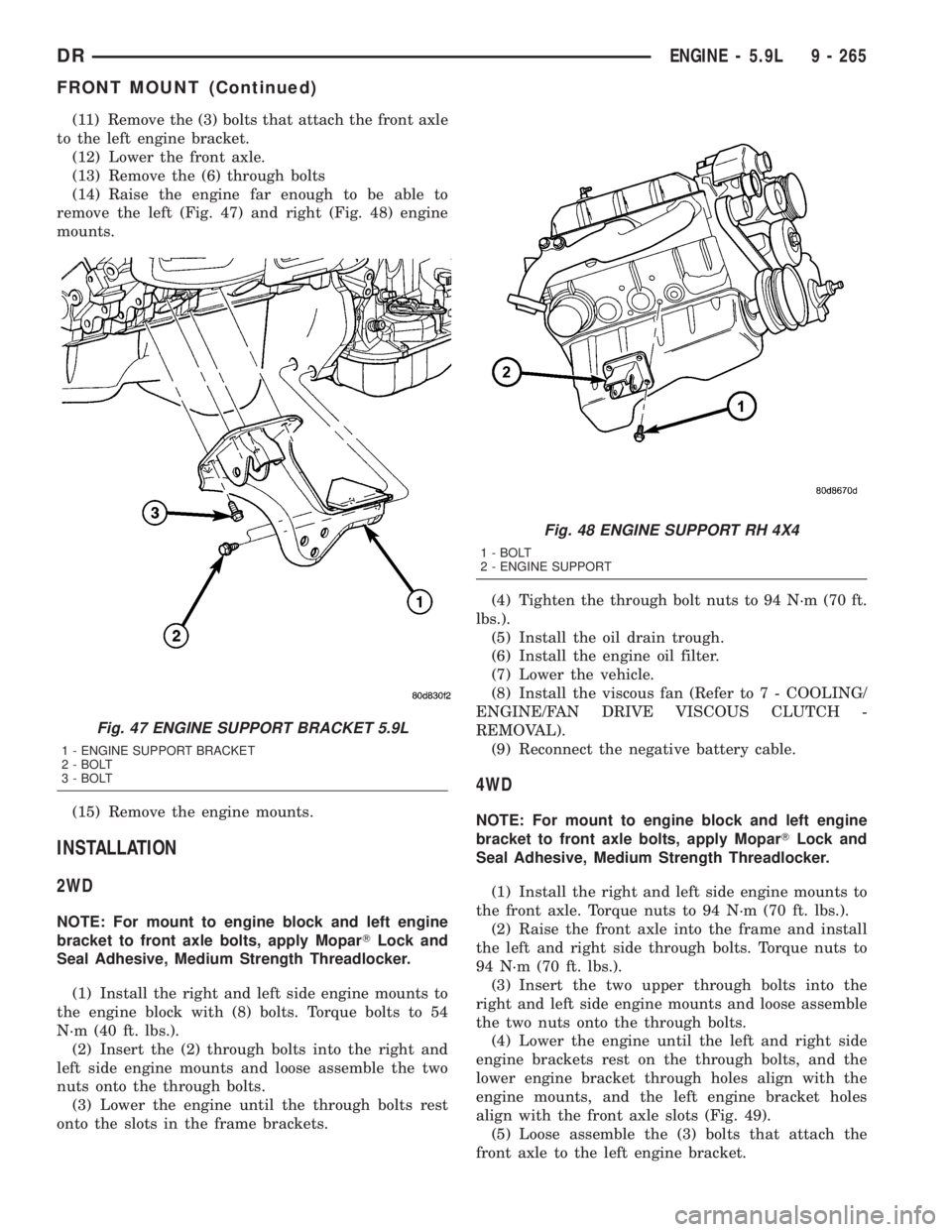
remove the left (Fig. 47) and right (Fig. 48) engine
mounts.
(15) Remove the engine mounts.
INSTALLATION
2WD
NOTE: For mount to engine block and left engine
bracket to front axle bolts, apply MoparTLock and
Seal Adhesive, Medium Strength Threadlocker.
(1) Install the right and left side engine mounts to
the engine block with (8) bolts. Torque bolts to 54
N´m (40 ft. lbs.).
(2) Insert the (2) through bolts into the right and
left side engine mounts and loose assemble the two
nuts onto the through bolts.
(3) Lower the engine until the through bolts rest
onto the slots in the frame brackets.(4) Tighten the through bolt nuts to 94 N´m (70 ft.
lbs.).
(5) Install the oil drain trough.
(6) Install the engine oil filter.
(7) Lower the vehicle.
(8) Install the viscous fan (Refer to 7 - COOLING/
ENGINE/FAN DRIVE VISCOUS CLUTCH -
REMOVAL).
(9) Reconnect the negative battery cable.
4WD
NOTE: For mount to engine block and left engine
bracket to front axle bolts, apply MoparTLock and
Seal Adhesive, Medium Strength Threadlocker.
(1) Install the right and left side engine mounts to
the front axle. Torque nuts to 94 N´m (70 ft. lbs.).
(2) Raise the front axle into the frame and install
the left and right side through bolts. Torque nuts to
94 N´m (70 ft. lbs.).
(3) Insert the two upper through bolts into the
right and left side engine mounts and loose assemble
the two nuts onto the through bolts.
(4) Lower the engine until the left and right side
engine brackets rest on the through bolts, and the
lower engine bracket through holes align with the
engine mounts, and the left engine bracket holes
align with the front axle slots (Fig. 49).
(5) Loose assemble the (3) bolts that attach the
front axle to the left engine bracket.
Fig. 47 ENGINE SUPPORT BRACKET 5.9L
1 - ENGINE SUPPORT BRACKET
2 - BOLT
3 - BOLT
Fig. 48 ENGINE SUPPORT RH 4X4
1 - BOLT
2 - ENGINE SUPPORT
DRENGINE - 5.9L 9 - 265
FRONT MOUNT (Continued)