2003 DODGE RAM oil change
[x] Cancel search: oil changePage 1433 of 2895
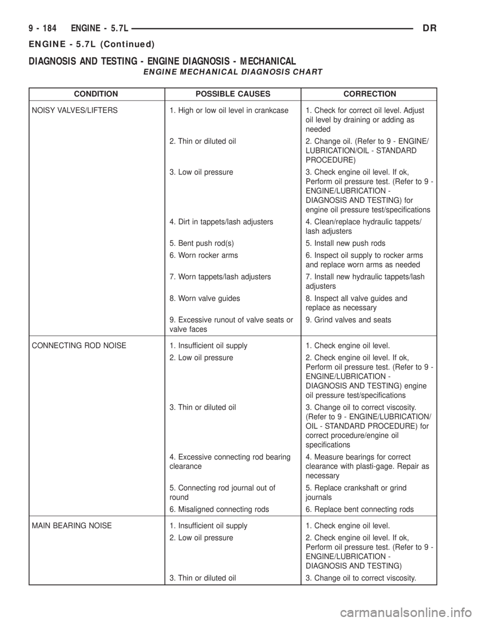
DIAGNOSIS AND TESTING - ENGINE DIAGNOSIS - MECHANICAL
ENGINE MECHANICAL DIAGNOSIS CHART
CONDITION POSSIBLE CAUSES CORRECTION
NOISY VALVES/LIFTERS 1. High or low oil level in crankcase 1. Check for correct oil level. Adjust
oil level by draining or adding as
needed
2. Thin or diluted oil 2. Change oil. (Refer to 9 - ENGINE/
LUBRICATION/OIL - STANDARD
PROCEDURE)
3. Low oil pressure 3. Check engine oil level. If ok,
Perform oil pressure test. (Refer to 9 -
ENGINE/LUBRICATION -
DIAGNOSIS AND TESTING) for
engine oil pressure test/specifications
4. Dirt in tappets/lash adjusters 4. Clean/replace hydraulic tappets/
lash adjusters
5. Bent push rod(s) 5. Install new push rods
6. Worn rocker arms 6. Inspect oil supply to rocker arms
and replace worn arms as needed
7. Worn tappets/lash adjusters 7. Install new hydraulic tappets/lash
adjusters
8. Worn valve guides 8. Inspect all valve guides and
replace as necessary
9. Excessive runout of valve seats or
valve faces9. Grind valves and seats
CONNECTING ROD NOISE 1. Insufficient oil supply 1. Check engine oil level.
2. Low oil pressure 2. Check engine oil level. If ok,
Perform oil pressure test. (Refer to 9 -
ENGINE/LUBRICATION -
DIAGNOSIS AND TESTING) engine
oil pressure test/specifications
3. Thin or diluted oil 3. Change oil to correct viscosity.
(Refer to 9 - ENGINE/LUBRICATION/
OIL - STANDARD PROCEDURE) for
correct procedure/engine oil
specifications
4. Excessive connecting rod bearing
clearance4. Measure bearings for correct
clearance with plasti-gage. Repair as
necessary
5. Connecting rod journal out of
round5. Replace crankshaft or grind
journals
6. Misaligned connecting rods 6. Replace bent connecting rods
MAIN BEARING NOISE 1. Insufficient oil supply 1. Check engine oil level.
2. Low oil pressure 2. Check engine oil level. If ok,
Perform oil pressure test. (Refer to 9 -
ENGINE/LUBRICATION -
DIAGNOSIS AND TESTING)
3. Thin or diluted oil 3. Change oil to correct viscosity.
9 - 184 ENGINE - 5.7LDR
ENGINE - 5.7L (Continued)
Page 1434 of 2895
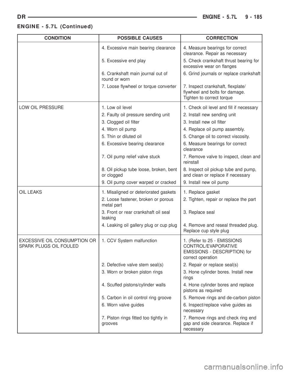
CONDITION POSSIBLE CAUSES CORRECTION
4. Excessive main bearing clearance 4. Measure bearings for correct
clearance. Repair as necessary
5. Excessive end play 5. Check crankshaft thrust bearing for
excessive wear on flanges
6. Crankshaft main journal out of
round or worn6. Grind journals or replace crankshaft
7. Loose flywheel or torque converter 7. Inspect crankshaft, flexplate/
flywheel and bolts for damage.
Tighten to correct torque
LOW OIL PRESSURE 1. Low oil level 1. Check oil level and fill if necessary
2. Faulty oil pressure sending unit 2. Install new sending unit
3. Clogged oil filter 3. Install new oil filter
4. Worn oil pump 4. Replace oil pump assembly.
5. Thin or diluted oil 5. Change oil to correct viscosity.
6. Excessive bearing clearance 6. Measure bearings for correct
clearance
7. Oil pump relief valve stuck 7. Remove valve to inspect, clean and
reinstall
8. Oil pickup tube loose, broken, bent
or clogged8. Inspect oil pickup tube and pump,
and clean or replace if necessary
9. Oil pump cover warped or cracked 9. Install new oil pump
OIL LEAKS 1. Misaligned or deteriorated gaskets 1. Replace gasket
2. Loose fastener, broken or porous
metal part2. Tighten, repair or replace the part
3. Front or rear crankshaft oil seal
leaking3. Replace seal
4. Leaking oil gallery plug or cup plug 4. Remove and reseal threaded plug.
Replace cup style plug
EXCESSIVE OIL CONSUMPTION OR
SPARK PLUGS OIL FOULED1. CCV System malfunction 1. (Refer to 25 - EMISSIONS
CONTROL/EVAPORATIVE
EMISSIONS - DESCRIPTION) for
correct operation
2. Defective valve stem seal(s) 2. Repair or replace seal(s)
3. Worn or broken piston rings 3. Hone cylinder bores. Install new
rings
4. Scuffed pistons/cylinder walls 4. Hone cylinder bores and replace
pistons as required
5. Carbon in oil control ring groove 5. Remove rings and de-carbon piston
6. Worn valve guides 6. Inspect/replace valve guides as
necessary
7. Piston rings fitted too tightly in
grooves7. Remove rings and check ring end
gap and side clearance. Replace if
necessary
DRENGINE - 5.7L 9 - 185
ENGINE - 5.7L (Continued)
Page 1447 of 2895
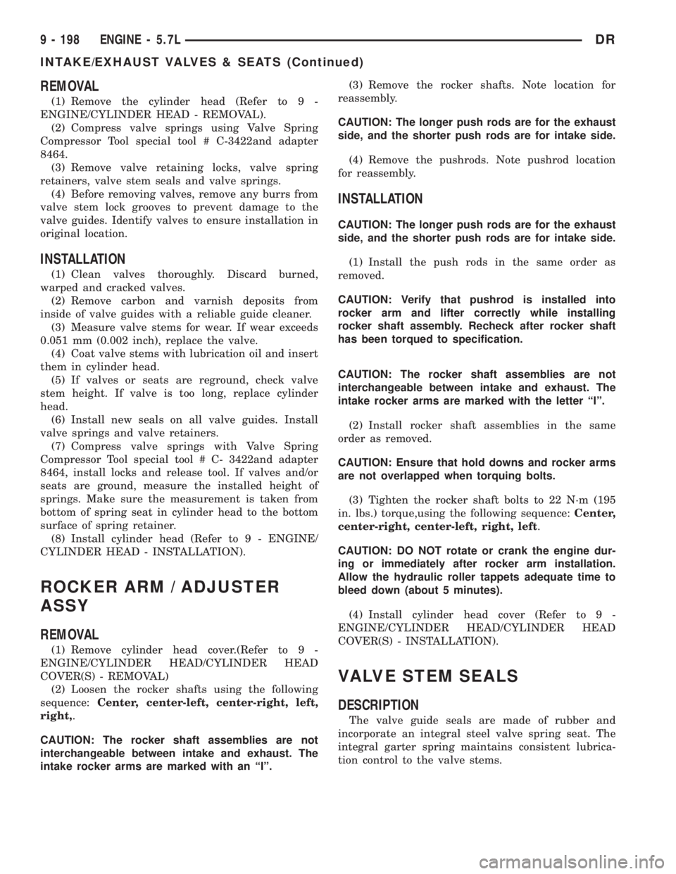
REMOVAL
(1) Remove the cylinder head (Refer to 9 -
ENGINE/CYLINDER HEAD - REMOVAL).
(2) Compress valve springs using Valve Spring
Compressor Tool special tool # C-3422and adapter
8464.
(3) Remove valve retaining locks, valve spring
retainers, valve stem seals and valve springs.
(4) Before removing valves, remove any burrs from
valve stem lock grooves to prevent damage to the
valve guides. Identify valves to ensure installation in
original location.
INSTALLATION
(1) Clean valves thoroughly. Discard burned,
warped and cracked valves.
(2) Remove carbon and varnish deposits from
inside of valve guides with a reliable guide cleaner.
(3) Measure valve stems for wear. If wear exceeds
0.051 mm (0.002 inch), replace the valve.
(4) Coat valve stems with lubrication oil and insert
them in cylinder head.
(5) If valves or seats are reground, check valve
stem height. If valve is too long, replace cylinder
head.
(6) Install new seals on all valve guides. Install
valve springs and valve retainers.
(7) Compress valve springs with Valve Spring
Compressor Tool special tool # C- 3422and adapter
8464, install locks and release tool. If valves and/or
seats are ground, measure the installed height of
springs. Make sure the measurement is taken from
bottom of spring seat in cylinder head to the bottom
surface of spring retainer.
(8) Install cylinder head (Refer to 9 - ENGINE/
CYLINDER HEAD - INSTALLATION).
ROCKER ARM / ADJUSTER
ASSY
REMOVAL
(1) Remove cylinder head cover.(Refer to 9 -
ENGINE/CYLINDER HEAD/CYLINDER HEAD
COVER(S) - REMOVAL)
(2) Loosen the rocker shafts using the following
sequence:Center, center-left, center-right, left,
right,.
CAUTION: The rocker shaft assemblies are not
interchangeable between intake and exhaust. The
intake rocker arms are marked with an ªIº.(3) Remove the rocker shafts. Note location for
reassembly.
CAUTION: The longer push rods are for the exhaust
side, and the shorter push rods are for intake side.
(4) Remove the pushrods. Note pushrod location
for reassembly.
INSTALLATION
CAUTION: The longer push rods are for the exhaust
side, and the shorter push rods are for intake side.
(1) Install the push rods in the same order as
removed.
CAUTION: Verify that pushrod is installed into
rocker arm and lifter correctly while installing
rocker shaft assembly. Recheck after rocker shaft
has been torqued to specification.
CAUTION: The rocker shaft assemblies are not
interchangeable between intake and exhaust. The
intake rocker arms are marked with the letter ªIº.
(2) Install rocker shaft assemblies in the same
order as removed.
CAUTION: Ensure that hold downs and rocker arms
are not overlapped when torquing bolts.
(3) Tighten the rocker shaft bolts to 22 N´m (195
in. lbs.) torque,using the following sequence:Center,
center-right, center-left, right, left.
CAUTION: DO NOT rotate or crank the engine dur-
ing or immediately after rocker arm installation.
Allow the hydraulic roller tappets adequate time to
bleed down (about 5 minutes).
(4) Install cylinder head cover (Refer to 9 -
ENGINE/CYLINDER HEAD/CYLINDER HEAD
COVER(S) - INSTALLATION).
VALVE STEM SEALS
DESCRIPTION
The valve guide seals are made of rubber and
incorporate an integral steel valve spring seat. The
integral garter spring maintains consistent lubrica-
tion control to the valve stems.
9 - 198 ENGINE - 5.7LDR
INTAKE/EXHAUST VALVES & SEATS (Continued)
Page 1448 of 2895
VALVE SPRINGS
REMOVAL
(1) Disconnect negative battery cable.
(2) Remove air cleaner assembly.
(3) Remove air intake resonator.
(4) Remove spark plug cables.
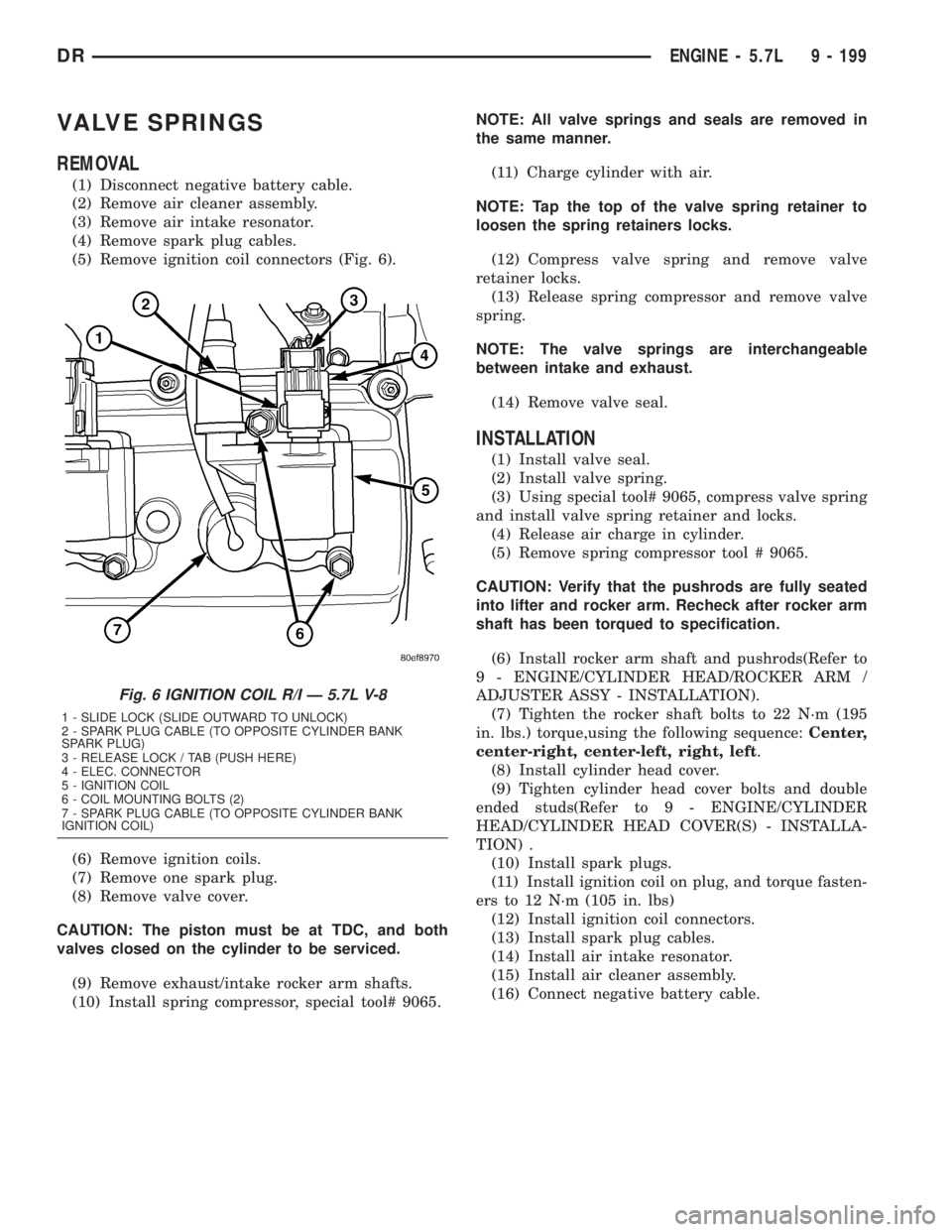
(5) Remove ignition coil connectors (Fig. 6).
(6) Remove ignition coils.
(7) Remove one spark plug.
(8) Remove valve cover.
CAUTION: The piston must be at TDC, and both
valves closed on the cylinder to be serviced.
(9) Remove exhaust/intake rocker arm shafts.
(10) Install spring compressor, special tool# 9065.NOTE: All valve springs and seals are removed in
the same manner.
(11) Charge cylinder with air.
NOTE: Tap the top of the valve spring retainer to
loosen the spring retainers locks.
(12) Compress valve spring and remove valve
retainer locks.
(13) Release spring compressor and remove valve
spring.
NOTE: The valve springs are interchangeable
between intake and exhaust.
(14) Remove valve seal.
INSTALLATION
(1) Install valve seal.
(2) Install valve spring.
(3) Using special tool# 9065, compress valve spring
and install valve spring retainer and locks.
(4) Release air charge in cylinder.
(5) Remove spring compressor tool # 9065.
CAUTION: Verify that the pushrods are fully seated
into lifter and rocker arm. Recheck after rocker arm
shaft has been torqued to specification.
(6) Install rocker arm shaft and pushrods(Refer to
9 - ENGINE/CYLINDER HEAD/ROCKER ARM /
ADJUSTER ASSY - INSTALLATION).
(7) Tighten the rocker shaft bolts to 22 N´m (195
in. lbs.) torque,using the following sequence:Center,
center-right, center-left, right, left.
(8) Install cylinder head cover.
(9) Tighten cylinder head cover bolts and double
ended studs(Refer to 9 - ENGINE/CYLINDER
HEAD/CYLINDER HEAD COVER(S) - INSTALLA-
TION) .
(10) Install spark plugs.
(11) Install ignition coil on plug, and torque fasten-
ers to 12 N´m (105 in. lbs)
(12) Install ignition coil connectors.
(13) Install spark plug cables.
(14) Install air intake resonator.
(15) Install air cleaner assembly.
(16) Connect negative battery cable.
Fig. 6 IGNITION COIL R/I Ð 5.7L V-8
1 - SLIDE LOCK (SLIDE OUTWARD TO UNLOCK)
2 - SPARK PLUG CABLE (TO OPPOSITE CYLINDER BANK
SPARK PLUG)
3 - RELEASE LOCK / TAB (PUSH HERE)
4 - ELEC. CONNECTOR
5 - IGNITION COIL
6 - COIL MOUNTING BOLTS (2)
7 - SPARK PLUG CABLE (TO OPPOSITE CYLINDER BANK
IGNITION COIL)
DRENGINE - 5.7L 9 - 199
Page 1456 of 2895
Check the piston for scoring, or scraping marks in
the piston skirts. Check the ring lands for cracks
and/or deterioration.
INSTALLATION
(1) Before installing piston and connecting rod
assemblies into the bore, install the piston rings(Re-
fer to 9 - ENGINE/ENGINE BLOCK/PISTON RINGS
- STANDARD PROCEDURE).
(2) Immerse the piston head and rings in clean
engine oil. Position a ring compressor over the piston
and rings. Tighten ring compressor.Ensure posi-
tion of rings do not change during this opera-
tion.
(3) Position bearing onto connecting rod. Lubricate
bearing surface with clean engine oil.
(4) Install Special Tool 8507 Connecting Rod
Guides into connecting rod bolt threads.
(5) The pistons are marked on the piston pin bore
surface with an raised ªFº or arrow on top of piston
indicating installation position. This mark must be
pointing toward the front of engine on both cylinder
banks. The connecting rod oil slinger slot faces the
front of the engine.
(6) Wipe cylinder bore clean and lubricate with
engine oil.
(7) Rotate crankshaft until connecting rod journal
is on the center of cylinder bore. Insert rod and pis-
ton into cylinder bore and carefully position connect-
ing rod guides over crankshaft journal.
(8) Tap piston down in cylinder bore using a ham-
mer handle. While at the same time, guide connect-
ing rod into position on rod journal.
CAUTION: Connecting Rod Bolts are Torque to
Yield Bolts and Must Not Be Reused. Always
replace the Rod Bolts whenever they are loosened
or removed.
(9) Lubricate rod bolts and bearing surfaces with
engine oil. Install connecting rod cap and bearing.
Tighten bolts to 21 N´m (15 ft. lbs.) plus a 90É turn.
(10) Install the following components:
²Cylinder head(s). (Refer to 9 - ENGINE/CYLIN-
DER HEAD - INSTALLATION).
²Cylinder head covers (Refer to 9 - ENGINE/
CYLINDER HEAD/CYLINDER HEAD COVER(S) -
INSTALLATION).²Install the intake manifold.
²Oil pan and gasket/windage tray. (Refer to 9 -
ENGINE/LUBRICATION/OIL PAN - INSTALLA-
TION).
(11) Fill crankcase with proper engine oil to cor-
rect level.
(12) Connect negative cable to battery.
PISTON RINGS
STANDARD PROCEDURE - PISTON RING
FITTING
Before reinstalling used rings or installing new
rings, the ring clearances must be checked.
(1) Wipe the cylinder bore clean.
(2) Insert the ring in the cylinder bore.
NOTE: The ring gap measurement must be made
with the ring positioned at least 12mm (0.50 inch.)
from bottom of cylinder bore.
(3) Using a piston, to ensure that the ring is
squared in the cylinder bore, slide the ring downward
into the cylinder.
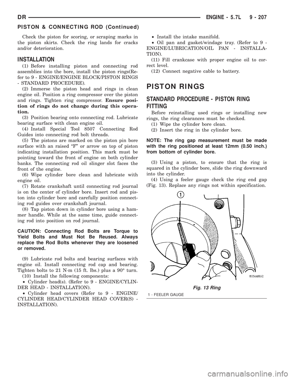
(4) Using a feeler gauge check the ring end gap
(Fig. 13). Replace any rings not within specification.
Fig. 13 Ring
1 - FEELER GAUGE
DRENGINE - 5.7L 9 - 207
PISTON & CONNECTING ROD (Continued)
Page 1465 of 2895
ENGINE OIL SPECIFICATION
CAUTION: Do not use non-detergent or straight
mineral oil when adding or changing crankcase
lubricant. Engine failure can result.
API SERVICE GRADE CERTIFIED
Use an engine oil that is API Service Grade Certi-
fied. MOPARtprovides engine oils that conform to
this service grade.
SAE VISCOSITY
An SAE viscosity grade is used to specify the vis-
cosity of engine oil. Use only engine oils with multi-
ple viscosities such as 5W-30 in the 5.7L engines.
These are specified with a dual SAE viscosity grade
which indicates the cold-to-hot temperature viscosity
range. Select an engine oil that is best suited to your
particular temperature range and variation.
ENERGY CONSERVING OIL
An Energy Conserving type oil is recommended for
gasoline engines. The designation of ENERGY CON-
SERVING is located on the label of an engine oil con-
tainer.
CONTAINER IDENTIFICATION
Standard engine oil identification notations have
been adopted to aid in the proper selection of engine
oil. The identifying notations are located on the label
of engine oil plastic bottles and the top of engine oil
cans (Fig. 26).
OIL LEVEL INDICATOR (DIPSTICK)
The engine oil level indicator is located at the left
hand of the engine on the 5.7L engines.
CRANKCASE OIL LEVEL INSPECTION
CAUTION: Do not overfill crankcase with engine oil,
pressure loss or oil foaming can result.
Inspect engine oil level approximately every 800
kilometers (500 miles). Unless the engine has exhib-
ited loss of oil pressure, run the engine for about tenminutes before checking oil level. Checking engine oil
level on a cold engine is not accurate.
To ensure proper lubrication of an engine, the
engine oil must be maintained at an acceptable level.
The acceptable levels are indicated between the ADD
and SAFE marks on the engine oil dipstick.
(1) Position vehicle on level surface.
(2) With engine OFF, allow approximately five
minutes for oil to settle to bottom of crankcase,
remove engine oil dipstick.
(3) Wipe dipstick clean.
(4) Install dipstick and verify it is seated in the
tube.
(5) Remove dipstick, with handle held above the
tip, take oil level reading.
(6) Add oil only if level is below the ADD mark on
dipstick.
ENGINE OIL CHANGE
Change engine oil at mileage and time intervals
described in Maintenance Schedules(Refer to LUBRI-
CATION & MAINTENANCE/MAINTENANCE
SCHEDULES - DESCRIPTION).
Run engine until achieving normal operating tem-
perature.
(1) Position the vehicle on a level surface and turn
engine off.
(2) Hoist and support vehicle on safety stands.
(3) Remove oil fill cap.
(4) Place a suitable drain pan under crankcase
drain.
(5) Remove drain plug from crankcase and allow
oil to drain into pan. Inspect drain plug threads for
stretching or other damage. Replace drain plug if
damaged.
(6) Install drain plug in crankcase. Torque to 34
N´m ( 25 ft. lbs.).
(7) Lower vehicle and fill crankcase with specified
type and amount of engine oil described in this sec-
tion.
(8) Install oil fill cap.
(9) Start engine and inspect for leaks.
(10) Stop engine and inspect oil level.
USED ENGINE OIL DISPOSAL
Care should be exercised when disposing used
engine oil after it has been drained from a vehicle
engine. Refer to the WARNING at beginning of this
section.
OIL FILTER
REMOVAL
All engines are equipped with a high quality full-
flow, disposable type oil filter. DaimlerChrysler Cor-
Fig. 26 API SYMBOL
9 - 216 ENGINE - 5.7LDR
OIL (Continued)
Page 1468 of 2895
INSTALLATION
(1) Position the oil pump onto the crankshaft and
install the 4 oil pump retaining bolts.
(2) Tighten the oil pump retaining bolts to 28 N´m
(250 in. lbs.).
(3) Install the timing chain cover(Refer to 9 -
ENGINE/VALVE TIMING/TIMING BELT / CHAIN
COVER(S) - INSTALLATION).
(4) Install the pick-up tube and oil pan(Refer to 9 -
ENGINE/LUBRICATION/OIL PAN - INSTALLA-
TION).
INTAKE MANIFOLD
DESCRIPTION
The intake manifold is made of a composite mate-
rial and features long runners which maximizes low
end torque. The intake manifold uses single plane
sealing which consist of eight individual press in
place port gaskets to prevent leaks.
DIAGNOSIS AND TESTING - INTAKE
MANIFOLD LEAKAGE
An intake manifold air leak is characterized by
lower than normal manifold vacuum. Also, one or
more cylinders may not be functioning.
WARNING: USE EXTREME CAUTION WHEN THE
ENGINE IS OPERATING. DO NOT STAND IN A
DIRECT LINE WITH THE FAN. DO NOT PUT YOUR
HANDS NEAR THE PULLEYS, BELTS OR THE FAN.
DO NOT WEAR LOOSE CLOTHING.
(1) Start the engine.(2) Spray a small stream of water at the suspected
leak area.
(3) If a change in RPM is observed the area of the
suspected leak has been found.
(4) Repair as required.
REMOVAL
(1) Disconnect negative cable from battery.
(2) Remove resonator assembly and air inlet hose.
(3) Disconnect electrical connectors for the follow-
ing components:
²Manifold Absolute Pressure (MAP) Sensor
²Intake Air Temperature (IAT) Sensor
²Throttle Position (TPS) Sensor
²Coolant Temperature (CTS) Sensor
(4) Disconnect brake booster hose and positive
crankcase ventilation (PCV) hose.
(5) Remove generator and set aside.
NOTE: It is not necessary to remove lines or
remove freon from A/C compressor.
(6) Remove air conditioning compressor and set
aside..
(7) Bleed fuel system (Refer to 14 - FUEL SYS-
TEM/FUEL DELIVERY - STANDARD PROCE-
DURE).
(8) Remove intake manifold retaining fasteners in
a crisscross pattern starting from the outside bolts
and ending at the middle bolts.
(9) Remove intake manifold and IAFM as an
assembly.
CLEANING
NOTE: There is NO approved repair procedure for
the intake manifold. If severe damage is found dur-
ing inspection, the intake manifold must be
replaced.
Before installing the intake manifold thoroughly
clean the mating surfaces. Use a suitable cleaning
solvent, then air dry.
INSPECTION
(1) Inspect the intake sealing surface for cracks,
nicks and distortion.
(2) Inspect the intake manifold vacuum hose fit-
tings for looseness or blockage.
(3) Inspect the manifold to throttle body mating
surface for cracks, nicks and distortion.
INSTALLATION
(1) Install intake manifold seals.
(2) Position intake manifold and IAFM.
(3) Install intake manifold retaining bolts, and
tighten in sequence from the middle bolts towards
Fig. 30 Measuring Clearance Over Rotors - Typical
1 - STRAIGHT EDGE
2 - FEELER GAUGE
DRENGINE - 5.7L 9 - 219
OIL PUMP (Continued)
Page 1477 of 2895
DIAGNOSIS AND TESTING - ENGINE DIAGNOSIS - MECHANICAL
ENGINE MECHANICAL DIAGNOSIS CHART
CONDITION POSSIBLE CAUSES CORRECTION
NOISY VALVES/LIFTERS 1. High or low oil level in crankcase 1. Check for correct oil level. Adjust
oil level by draining or adding as
needed
2. Thin or diluted oil 2. Change oil. (Refer to 9 - ENGINE/
LUBRICATION/OIL - STANDARD
PROCEDURE)
3. Low oil pressure 3. Check engine oil level. If ok,
Perform oil pressure test. (Refer to 9 -
ENGINE/LUBRICATION -
DIAGNOSIS AND TESTING) for
engine oil pressure test/specifications
4. Dirt in tappets/lash adjusters 4. Clean/replace hydraulic tappets/
lash adjusters
5. Bent push rod(s) 5. Install new push rods
6. Worn rocker arms 6. Inspect oil supply to rocker arms
and replace worn arms as needed
7. Worn tappets/lash adjusters 7. Install new hydraulic tappets/lash
adjusters
8. Worn valve guides 8. Inspect all valve guides and
replace as necessary
9. Excessive runout of valve seats or
valve faces9. Grind valves and seats
CONNECTING ROD NOISE 1. Insufficient oil supply 1. Check engine oil level.
2. Low oil pressure 2. Check engine oil level. If ok,
Perform oil pressure test. (Refer to 9 -
ENGINE/LUBRICATION -
DIAGNOSIS AND TESTING) engine
oil pressure test/specifications
3. Thin or diluted oil 3. Change oil to correct viscosity.
(Refer to 9 - ENGINE/LUBRICATION/
OIL - STANDARD PROCEDURE) for
correct procedure/engine oil
specifications
4. Excessive connecting rod bearing
clearance4. Measure bearings for correct
clearance with plasti-gage. Repair as
necessary
5. Connecting rod journal out of
round5. Replace crankshaft or grind
journals
6. Misaligned connecting rods 6. Replace bent connecting rods
MAIN BEARING NOISE 1. Insufficient oil supply 1. Check engine oil level.
2. Low oil pressure 2. Check engine oil level. If ok,
Perform oil pressure test. (Refer to 9 -
ENGINE/LUBRICATION -
DIAGNOSIS AND TESTING)
3. Thin or diluted oil 3. Change oil to correct viscosity.
9 - 228 ENGINE - 5.9LDR
ENGINE - 5.9L (Continued)