2003 DODGE RAM oil change
[x] Cancel search: oil changePage 1730 of 2895
INSTALLATION
(1) Install fuel injector(s) into fuel rail assembly
and install retaining clip(s).
(2) If same injector(s) is being reinstalled, install
new o-ring(s).
(3) Apply a small amount of clean engine oil to
each injector o-ring. This will aid in installation.
(4) Install fuel rail. Refer to Fuel Rail Installation.
(5) Start engine and check for fuel leaks.
FUEL PUMP RELAY
DESCRIPTION
The 5±pin, 12±volt, fuel pump relay is located in
the Power Distribution Center (PDC). Refer to the
label on the PDC cover for relay location.
OPERATION
The Powertrain Control Module (PCM) energizes
the electric fuel pump through the fuel pump relay.
The fuel pump relay is energized by first applying
battery voltage to it when the ignition key is turned
ON, and then applying a ground signal to the relay
from the PCM.
Whenever the ignition key is turned ON, the elec-
tric fuel pump will operate. But, the PCM will shut-
down the ground circuit to the fuel pump relay in
approximately 1±3 seconds unless the engine is oper-
ating or the starter motor is engaged.
REMOVAL
The fuel pump relay is located in the Power Distri-
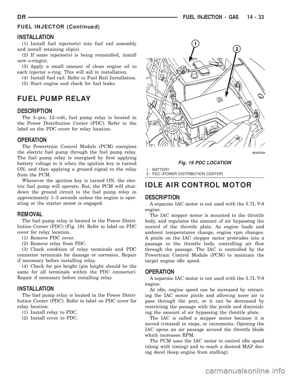
bution Center (PDC) (Fig. 19). Refer to label on PDC
cover for relay location.
(1) Remove PDC cover.
(2) Remove relay from PDC.
(3) Check condition of relay terminals and PDC
connector terminals for damage or corrosion. Repair
if necessary before installing relay.
(4) Check for pin height (pin height should be the
same for all terminals within the PDC connector).
Repair if necessary before installing relay.
INSTALLATION
The fuel pump relay is located in the Power Distri-
bution Center (PDC). Refer to label on PDC cover for
relay location.
(1) Install relay to PDC.
(2) Install cover to PDC.
IDLE AIR CONTROL MOTOR
DESCRIPTION
A separate IAC motor is not used with the 5.7L V-8
engine.
The IAC stepper motor is mounted to the throttle
body, and regulates the amount of air bypassing the
control of the throttle plate. As engine loads and
ambient temperatures change, engine rpm changes.
A pintle on the IAC stepper motor protrudes into a
passage in the throttle body, controlling air flow
through the passage. The IAC is controlled by the
Powertrain Control Module (PCM) to maintain the
target engine idle speed.
OPERATION
A separate IAC motor is not used with the 5.7L V-8
engine.
At idle, engine speed can be increased by retract-
ing the IAC motor pintle and allowing more air to
pass through the port, or it can be decreased by
restricting the passage with the pintle and diminish-
ing the amount of air bypassing the throttle plate.
The IAC is called a stepper motor because it is
moved (rotated) in steps, or increments. Opening the
IAC opens an air passage around the throttle blade
which increases RPM.
The PCM uses the IAC motor to control idle speed
(along with timing) and to reach a desired MAP dur-
ing decel (keep engine from stalling).
Fig. 19 PDC LOCATION
1 - BATTERY
2 - PDC (POWER DISTRIBUTION CENTER)
DRFUEL INJECTION - GAS 14 - 33
FUEL INJECTOR (Continued)
Page 1794 of 2895
STEERING
TABLE OF CONTENTS
page page
STEERING
DESCRIPTION..........................1
OPERATION............................1
DIAGNOSIS AND TESTING
DIAGNOSIS AND TESTING - POWER
STEERING SYSTEM....................2
DIAGNOSIS AND TESTING - POWER
STEERING FLOW AND PRESSURE........4
SPECIAL TOOLS
STEERING...........................5COLUMN...............................6
GEAR - INDEPENDENT FRONT SUSPENSION..16
GEAR - LINK/COIL.......................19
LINKAGE - INDEPENDENT FRONT
SUSPENSION...........................31
LINKAGE - LINK/COIL....................33
PUMP.................................38
STEERING
DESCRIPTION
CAUTION: MOPARTATF+4 is to be used in the
power steering system. No other power steering or
automatic transmission fluid is to be used in the
system. Damage may result to the power steering
pump and system if any other fluid is used, and do
not overfill.
Power steering systems consist of:
²Steering column
²Rack and pinion steering gear
²Belt driven hydraulic steering pump
²Pump pressure and return hoses
²Oil Cooler
OPERATION
The steering column shaft is attached to the gear
pinion. The rotation of the pinion moves the gear
rack from side-to-side. This lateral action of the rack
pushes and pulls the tie rods to change the direction
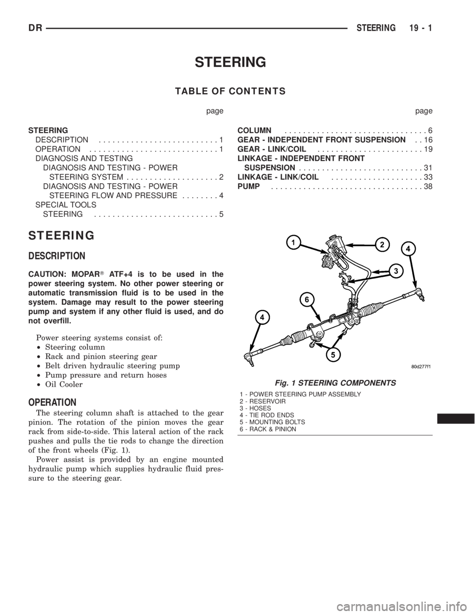
of the front wheels (Fig. 1).
Power assist is provided by an engine mounted
hydraulic pump which supplies hydraulic fluid pres-
sure to the steering gear.
Fig. 1 STEERING COMPONENTS
1 - POWER STEERING PUMP ASSEMBLY
2 - RESERVOIR
3 - HOSES
4 - TIE ROD ENDS
5 - MOUNTING BOLTS
6 - RACK & PINION
DRSTEERING 19 - 1
Page 1831 of 2895
PUMP
TABLE OF CONTENTS
page page
PUMP
DESCRIPTION.........................38
OPERATION...........................38
DIAGNOSIS AND TESTING - PUMP LEAKAGE . 39
STANDARD PROCEDURE
STANDARD PROCEDURE - POWER
STEERING PUMP - INITIAL OPERATION....39
STANDARD PROCEDURE - FLUSHING
POWER STEERING SYSTEM............39
REMOVAL
REMOVAL - GAS......................40
REMOVAL - DIESEL...................40
INSTALLATION
INSTALLATION - GAS..................41
INSTALLATION - DIESEL................41
SPECIFICATIONS
TORQUE CHART......................41
FLUID
DESCRIPTION.........................42
STANDARD PROCEDURE - POWER
STEERING FLUID LEVEL CHECKING......42
FLUID COOLER
REMOVAL.............................42
INSTALLATION.........................42
HOSES - I.F.S.
REMOVAL
REMOVAL - RETURN HOSE - GEAR TO
COOLER............................43
REMOVAL - PRESSURE HOSE...........43
REMOVAL - RETURN HOSE - RESERVOIR
TO COOLER.........................43INSTALLATION
INSTALLATION - RETURN HOSE - GEAR TO
COOLER............................43
INSTALLATION - PRESSURE HOSE.......43
INSTALLATION - RETURN HOSE -
RESERVOIR TO COOLER...............43
HOSES - LINK/COIL
REMOVAL
REMOVAL - RETURN HOSE - GEAR TO
COOLER............................43
REMOVAL - PRESSURE HOSE...........44
REMOVAL - RETURN HOSE - RESERVOIR
TO COOLER.........................44
INSTALLATION
INSTALLATION - RETURN HOSE - GEAR TO
COOLER............................44
INSTALLATION - PRESSURE HOSE.......44
INSTALLATION - RETURN HOSE -
RESERVOIR TO COOLER...............44
POWER STEERING PRESSURE SWITCH
DESCRIPTION.........................45
OPERATION...........................45
REMOVAL - 3.7L, 4.7L & 5.7L..............45
INSTALLATION - 3.7L, 4.7L & 5.7L..........45
PULLEY
REMOVAL.............................45
INSTALLATION.........................46
RESERVOIR
REMOVAL.............................46
INSTALLATION.........................46
PUMP
DESCRIPTION
CAUTION: MOPARTATF+4 is to be used in the
power steering system. No other power steering or
automatic transmission fluid is to be used in the
system. Damage may result to the power steering
pump and system if any other fluid is used, and do
not overfill.
The pump is connected to the steering gear via the
pressure hose and the return hose. The pump shaft
has a pressed-on pulley that is belt driven by the
crankshaft pulley.All vehicles are equipped with a power steering
fluid cooler.
NOTE: Power steering pumps are not interchange-
able with pumps installed on other vehicles.
OPERATION
Hydraulic pressure is provided for the power steer-
ing gear by the belt driven power steering pump (Fig.
1). The power steering pumps are constant flow rate
and displacement, vane-type pumps.
19 - 38 PUMPDR
Page 1835 of 2895
FLUID
DESCRIPTION
The recommended fluid for the power steering sys-
tem is MopartATF +4.
MopartATF+4, when new is red in color. The
ATF+4 is dyed red so it can be identified from other
fluids used in the vehicle such as engine oil or anti-
freeze. The red color is not permanent and is not an
indicator of fluid condition, As the vehicle is driven,
the ATF+4 will begin to look darker in color and may
eventually become brown.THIS IS NORMAL.
ATF+4 also has a unique odor that may change with
age. Consequently, odor and color cannot be used to
indicate the fluid condition or the need for a fluid
change.
STANDARD PROCEDURE - POWER STEERING
FLUID LEVEL CHECKING
WARNING: FLUID LEVEL SHOULD BE CHECKED
WITH THE ENGINE OFF TO PREVENT PERSONAL
INJURY FROM MOVING PARTS.
CAUTION: MOPARTATF+4 is to be used in the
power steering system. No other power steering or
automatic transmission fluid is to be used in the
system. Damage may result to the power steering
pump and system if any other fluid is used, and do
not overfill.
The power steering fluid level can be viewed on the
dipstick attached to the filler cap. There are two
ranges listed on the dipstick, COLD and HOT. Before
opening power steering system, wipe the reservoir
filler cap free of dirt and debris. Remove the cap and
check the fluid level on its dipstick. When the fluid is
at normal ambient temperature, approximately 21ÉC
to 27ÉC (70ÉF to 80ÉF), the fluid level should read
between the minimum and maximum area of the cold
range. When the fluid is hot, fluid level is allowed to
read up to the highest end of the HOT range. Only
add fluid when the vehicle is cold.
Use only MopartATF+4Do not overfill the
power steering system.
FLUID COOLER
REMOVAL
(1) Drain and siphon the power steering fluid.
(2) Disconnect the return and supply hoses con-
nected to the power steering fluid cooler.(3) Remove the mounting bracket bolts securing
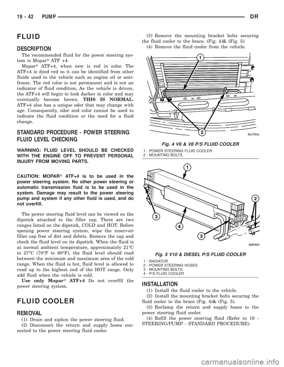
the fluid cooler to the brace. (Fig. 4)& (Fig. 5)
(4) Remove the fluid cooler from the vehicle.
INSTALLATION
(1) Install the fluid cooler to the vehicle.
(2) Install the mounting bracket bolts securing the
fluid cooler to the brace (Fig. 4)& (Fig. 5).
(3) Reclamp the return and supply hoses to the
power steering fluid cooler.
(4) Refill the power steering fluid (Refer to 19 -
STEERING/PUMP - STANDARD PROCEDURE).
Fig. 4 V6 & V8 P/S FLUID COOLER
1 - POWER STEERING FLUID COOLER
2 - MOUNTING BOLTS
Fig. 5 V10 & DIESEL P/S FLUID COOLER
1 - RADIATOR
2 - POWER STEERING HOSES
3 - MOUNTING BOLTS
4 - P/S FLUID COOLER
19 - 42 PUMPDR
Page 1855 of 2895
FRONT/REAR HOUSINGS AND BEARING
RETAINERS
Inspect the housings carefully. Look for cracks,
stripped threads, scored mating surfaces, damaged
bearing bores or worn dowel pin holes. Minor nicks
on mating surfaces can be dressed off with a fine file
or emery cloth. Damaged threads can be renewed by
either re-tapping or installing Helicoil inserts.
NOTE: The front housing contains the countershaft
front bearing race. The rear housing contains the
countershaft rear bearing race. These components
are NOT serviceable items. The front housing will
have to be replaced if the countershaft bearing race
is loose, worn or damaged. The rear housing will
have to be replaced if the countershaft rear bearing
race is loose, worn or damaged.
Inspect the input shaft bearing retainer. Be sure
the release bearing slide surface of the retainer is in
good condition. Minor nicks on the surface can be
smoothed off with 320/420 grit emery cloth and final
polished with oil coated crocus cloth. Replace the
retainer seal if necessary.
Inspect output shaft bearing retainer, the
U-shaped retainer must be flat and free of distortion.
Replace the retainer if the threads are damaged or if
the retainer is bent or cracked.
COUNTERSHAFT BEARINGS AND RACES
The countershaft bearings and races are machine
lapped during manufacture to form matched sets.
The bearings and races should not be interchanged.
NOTE: The bearing races are a permanent press fit
in the housings and are NOT serviceable. If a bear-
ing race becomes damaged, the front or rear hous-
ing must be replaced. A new countershaft bearing
will be supplied with each new housing for service
use.
REVERSE IDLER COMPONENTS
Inspect the idler gear, bearing, shaft, thrust
washer, wave washer and thrust plate. Replace the
bearing if any of the needle bearing rollers are worn,
chipped, cracked, flat-spotted or brinnelled. Also
replace the bearing if the plastic bearing cage is
damaged or distorted.
Replace thrust washer, wave washer or thrust
plate if cracked, chipped or worn. Replace idler gear
if the teeth are chipped, cracked or worn thin.
Replace shaft if worn, scored or the bolt threads are
damaged beyond repair. Replace support segment if
cracked or chipped and replace the idler attaching
bolts if the threads are damaged.
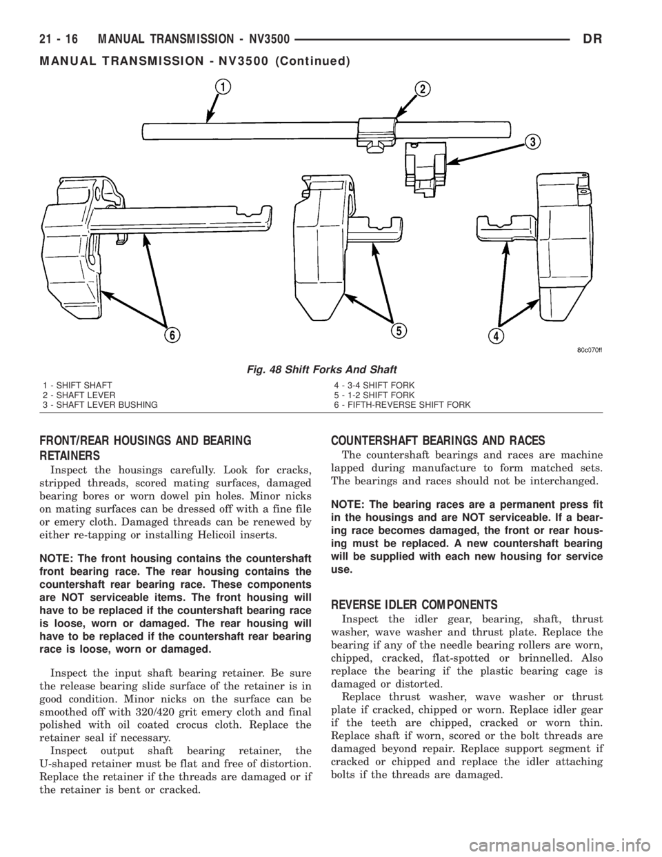
Fig. 48 Shift Forks And Shaft
1 - SHIFT SHAFT
2 - SHAFT LEVER
3 - SHAFT LEVER BUSHING4 - 3-4 SHIFT FORK
5 - 1-2 SHIFT FORK
6 - FIFTH-REVERSE SHIFT FORK
21 - 16 MANUAL TRANSMISSION - NV3500DR
MANUAL TRANSMISSION - NV3500 (Continued)
Page 1981 of 2895
Test Four - Transmission In Reverse
This test checks pump output, pressure regulation
and the front clutch and rear servo circuits. Use 300
psi Test Gauge C-3293-SP for this test.
(1) Leave vehicle on hoist and leave gauge C-3292
in place at accumulator port.
(2) Move 300 psi Gauge C-3293-SP back to rear
servo port.
(3) Have helper start and run engine at 1600 rpm
for test.
(4) Move transmission shift lever four detents
rearward from full forward position. This is Reverse
range.
(5) Move transmission throttle lever fully forward
then fully rearward and note reading at Gauge
C-3293-SP.
(6) Pressure should be 145 - 175 psi (1000-1207
kPa) with throttle lever forward and increase to 230 -
280 psi (1586-1931 kPa) as lever is gradually moved
rearward.
Test Five - Governor Pressure
This test checks governor operation by measuring
governor pressure response to changes in vehicle
speed. It is usually not necessary to check governor
operation unless shift speeds are incorrect or if the
transmission will not downshift. The test should be
performed on the road or on a hoist that will allow
the rear wheels to rotate freely.
(1) Move 100 psi Test Gauge C-3292 to governor
pressure port.
(2) Move transmission shift lever two detents rear-
ward from full forward position. This is D range.
(3) Have helper start and run engine at curb idle
speed. Then firmly apply service brakes so wheels
will not rotate.
(4) Note governor pressure:
²Governor pressure should be no more than 20.6
kPa (3 psi) at curb idle speed and wheels not rotat-
ing.
²If pressure exceeds 20.6 kPa (3 psi), a fault
exists in governor pressure control system.
(5) Release brakes, slowly increase engine speed,
and observe speedometer and pressure test gauge (do
not exceed 30 mph on speedometer). Governor pres-
sure should increase in proportion to vehicle speed.
Or approximately 6.89 kPa (1 psi) for every 1 mph.
(6) Governor pressure rise should be smooth and
drop back to no more than 20.6 kPa (3 psi), after
engine returns to curb idle and brakes are applied to
prevent wheels from rotating.
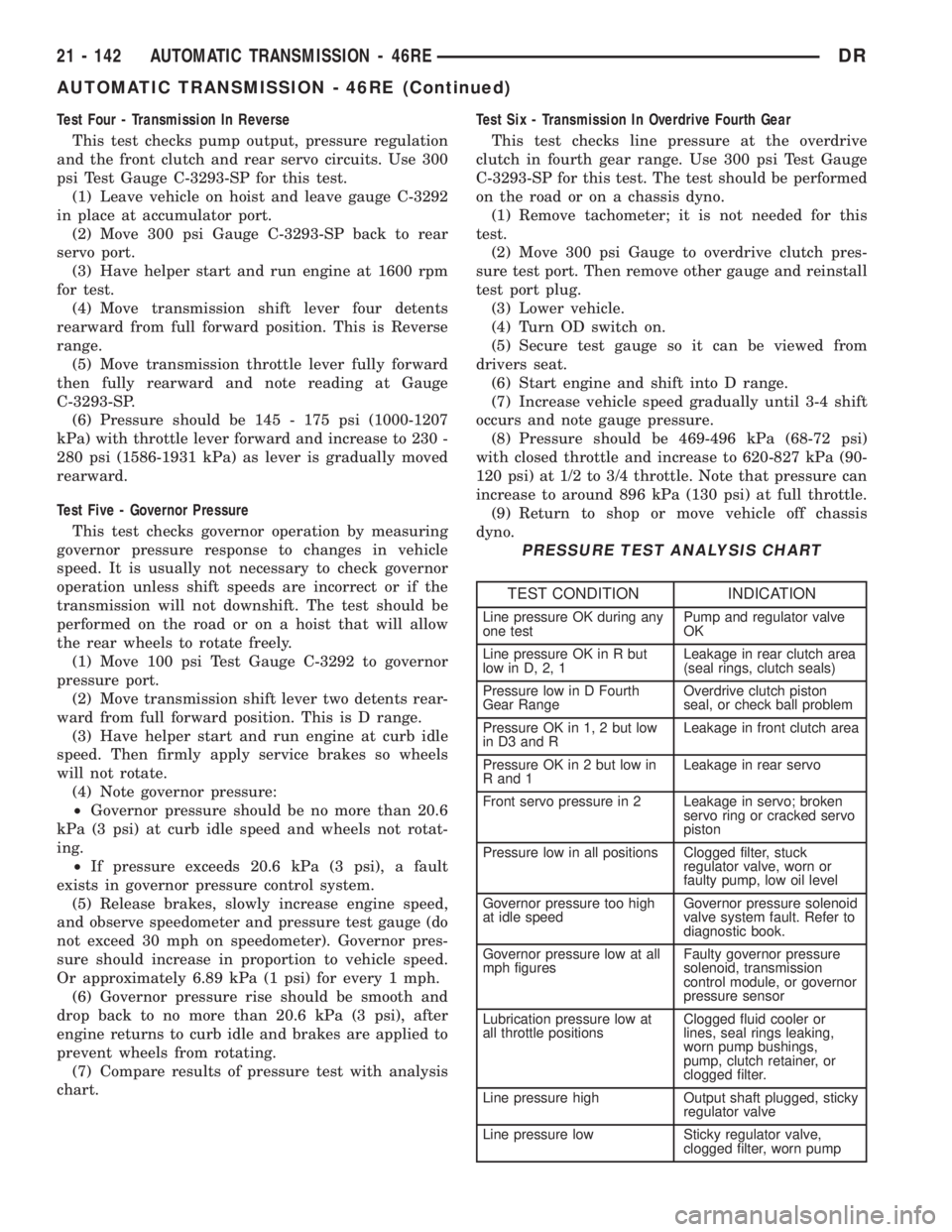
(7) Compare results of pressure test with analysis
chart.Test Six - Transmission In Overdrive Fourth Gear
This test checks line pressure at the overdrive
clutch in fourth gear range. Use 300 psi Test Gauge
C-3293-SP for this test. The test should be performed
on the road or on a chassis dyno.
(1) Remove tachometer; it is not needed for this
test.
(2) Move 300 psi Gauge to overdrive clutch pres-
sure test port. Then remove other gauge and reinstall
test port plug.
(3) Lower vehicle.
(4) Turn OD switch on.
(5) Secure test gauge so it can be viewed from
drivers seat.
(6) Start engine and shift into D range.
(7) Increase vehicle speed gradually until 3-4 shift
occurs and note gauge pressure.
(8) Pressure should be 469-496 kPa (68-72 psi)
with closed throttle and increase to 620-827 kPa (90-
120 psi) at 1/2 to 3/4 throttle. Note that pressure can
increase to around 896 kPa (130 psi) at full throttle.
(9) Return to shop or move vehicle off chassis
dyno.
PRESSURE TEST ANALYSIS CHART
TEST CONDITION INDICATION
Line pressure OK during any
one testPump and regulator valve
OK
Line pressure OK in R but
low in D, 2, 1Leakage in rear clutch area
(seal rings, clutch seals)
Pressure low in D Fourth
Gear RangeOverdrive clutch piston
seal, or check ball problem
Pressure OK in 1, 2 but low
in D3 and RLeakage in front clutch area
Pressure OK in 2 but low in
R and 1Leakage in rear servo
Front servo pressure in 2 Leakage in servo; broken
servo ring or cracked servo
piston
Pressure low in all positions Clogged filter, stuck
regulator valve, worn or
faulty pump, low oil level
Governor pressure too high
at idle speedGovernor pressure solenoid
valve system fault. Refer to
diagnostic book.
Governor pressure low at all
mph figuresFaulty governor pressure
solenoid, transmission
control module, or governor
pressure sensor
Lubrication pressure low at
all throttle positionsClogged fluid cooler or
lines, seal rings leaking,
worn pump bushings,
pump, clutch retainer, or
clogged filter.
Line pressure high Output shaft plugged, sticky
regulator valve
Line pressure low Sticky regulator valve,
clogged filter, worn pump
21 - 142 AUTOMATIC TRANSMISSION - 46REDR
AUTOMATIC TRANSMISSION - 46RE (Continued)
Page 1984 of 2895
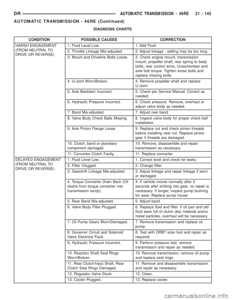
DIAGNOSIS CHARTS
CONDITION POSSIBLE CAUSES CORRECTION
HARSH ENGAGEMENT
(FROM NEUTRAL TO
DRIVE OR REVERSE)1. Fluid Level Low. 1. Add Fluid
2. Throttle Linkage Mis-adjusted. 2. Adjust linkage - setting may be too long.
3. Mount and Driveline Bolts Loose. 3. Check engine mount, transmission
mount, propeller shaft, rear spring to body
bolts, rear control arms, crossmember and
axle bolt torque. Tighten loose bolts and
replace missing bolts.
4. U-Joint Worn/Broken. 4. Remove propeller shaft and replace
U-Joint.
5. Axle Backlash Incorrect. 5. Check per Service Manual. Correct as
needed.
6. Hydraulic Pressure Incorrect. 6. Check pressure. Remove, overhaul or
adjust valve body as needed.
7. Band Mis-adjusted. 7. Adjust rear band.
8. Valve Body Check Balls Missing. 8. Inspect valve body for proper check ball
installation.
9. Axle Pinion Flange Loose. 9. Replace nut and check pinion threads
before installing new nut. Replace pinion
gear if threads are damaged.
10. Clutch, band or planetary
component damaged.10. Remove, disassemble and repair
transmission as necessary.
11. Converter Clutch Faulty. 11. Replace converter.
DELAYED ENGAGEMENT
(FROM NEUTRAL TO
DRIVE OR REVERSE)1. Fluid Level Low. 1. Correct level and check for leaks.
2. Filter Clogged. 2. Change filter.
3. Gearshift Linkage Mis-adjusted. 3. Adjust linkage and repair linkage if worn
or damaged.
4. Torque Converter Drain Back (Oil
drains from torque converter into
transmission sump).4. If vehicle moves normally after 5
seconds after shifting into gear, no repair is
necessary. If longer, inspect pump bushing
for wear. Replace pump house.
5. Rear Band Mis-adjusted. 5. Adjust band.
6. Valve Body Filter Plugged. 6. Replace fluid and filter. If oil pan and old
fluid were full of clutch disc material and/or
metal particles, overhaul will be necessary.
7. Oil Pump Gears Worn/Damaged. 7. Remove transmission and replace oil
pump.
8. Governor Circuit and Solenoid
Valve Electrical Fault.8. Test with DRBTscan tool and repair as
required.
9. Hydraulic Pressure Incorrect. 9. Perform pressure test, remove
transmission and repair as needed.
10. Reaction Shaft Seal Rings
Worn/Broken.10. Remove transmission, remove oil pump
and replace seal rings.
11. Rear Clutch/Input Shaft, Rear
Clutch Seal Rings Damaged.11. Remove and disassemble transmission
and repair as necessary.
12. Regulator Valve Stuck. 12. Clean.
13. Cooler Plugged. 13. Replace cooler.
DRAUTOMATIC TRANSMISSION - 46RE 21 - 145
AUTOMATIC TRANSMISSION - 46RE (Continued)
Page 2027 of 2895
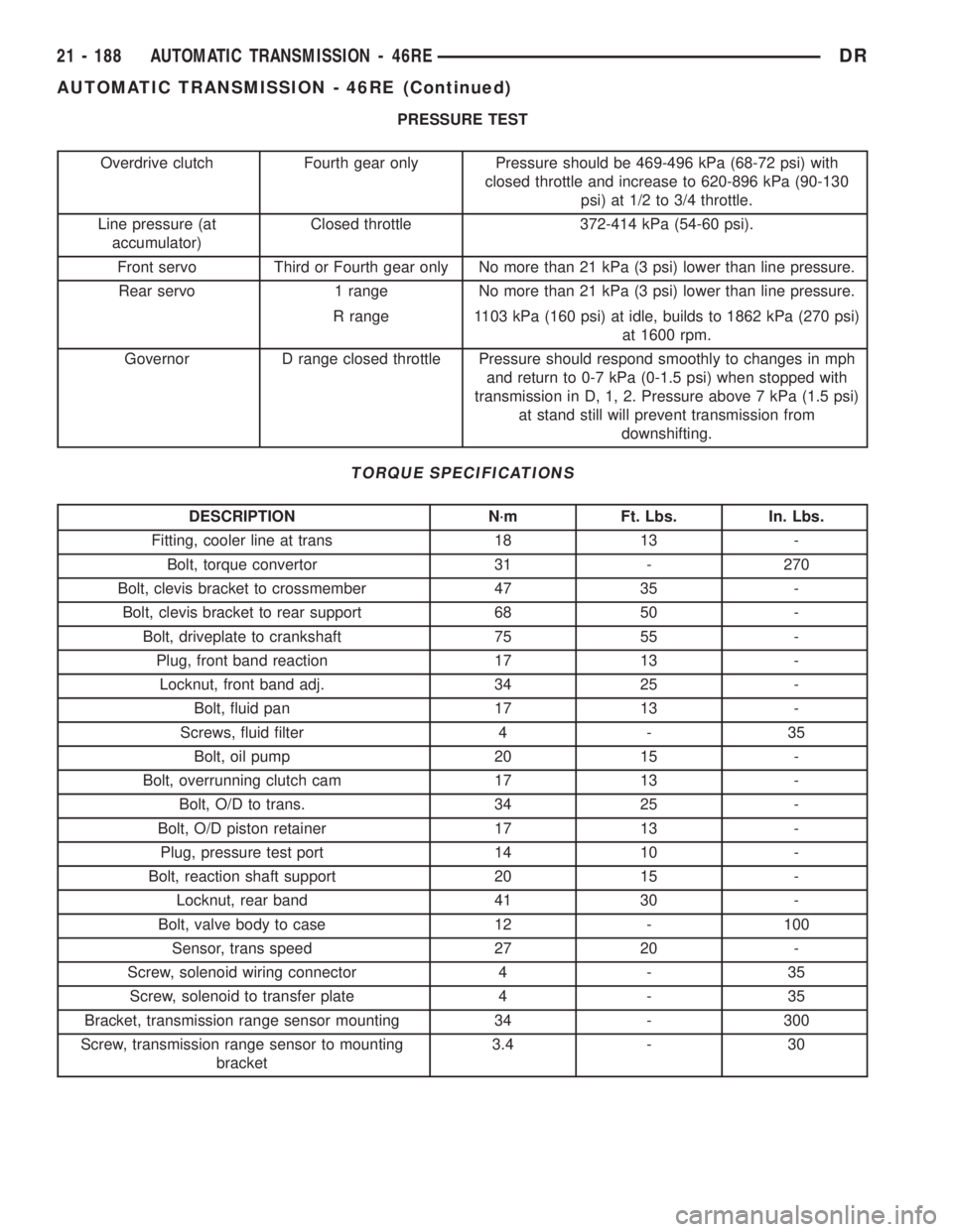
PRESSURE TEST
Overdrive clutch Fourth gear only Pressure should be 469-496 kPa (68-72 psi) with
closed throttle and increase to 620-896 kPa (90-130
psi) at 1/2 to 3/4 throttle.
Line pressure (at
accumulator)Closed throttle 372-414 kPa (54-60 psi).
Front servo Third or Fourth gear only No more than 21 kPa (3 psi) lower than line pressure.
Rear servo 1 range No more than 21 kPa (3 psi) lower than line pressure.
R range 1103 kPa (160 psi) at idle, builds to 1862 kPa (270 psi)
at 1600 rpm.
Governor D range closed throttle Pressure should respond smoothly to changes in mph
and return to 0-7 kPa (0-1.5 psi) when stopped with
transmission in D, 1, 2. Pressure above 7 kPa (1.5 psi)
at stand still will prevent transmission from
downshifting.
TORQUE SPECIFICATIONS
DESCRIPTION N´m Ft. Lbs. In. Lbs.
Fitting, cooler line at trans 18 13 -
Bolt, torque convertor 31 - 270
Bolt, clevis bracket to crossmember 47 35 -
Bolt, clevis bracket to rear support 68 50 -
Bolt, driveplate to crankshaft 75 55 -
Plug, front band reaction 17 13 -
Locknut, front band adj. 34 25 -
Bolt, fluid pan 17 13 -
Screws, fluid filter 4 - 35
Bolt, oil pump 20 15 -
Bolt, overrunning clutch cam 17 13 -
Bolt, O/D to trans. 34 25 -
Bolt, O/D piston retainer 17 13 -
Plug, pressure test port 14 10 -
Bolt, reaction shaft support 20 15 -
Locknut, rear band 41 30 -
Bolt, valve body to case 12 - 100
Sensor, trans speed 27 20 -
Screw, solenoid wiring connector 4 - 35
Screw, solenoid to transfer plate 4 - 35
Bracket, transmission range sensor mounting 34 - 300
Screw, transmission range sensor to mounting
bracket3.4 - 30
21 - 188 AUTOMATIC TRANSMISSION - 46REDR
AUTOMATIC TRANSMISSION - 46RE (Continued)