2003 DODGE RAM oil change
[x] Cancel search: oil changePage 1630 of 2895
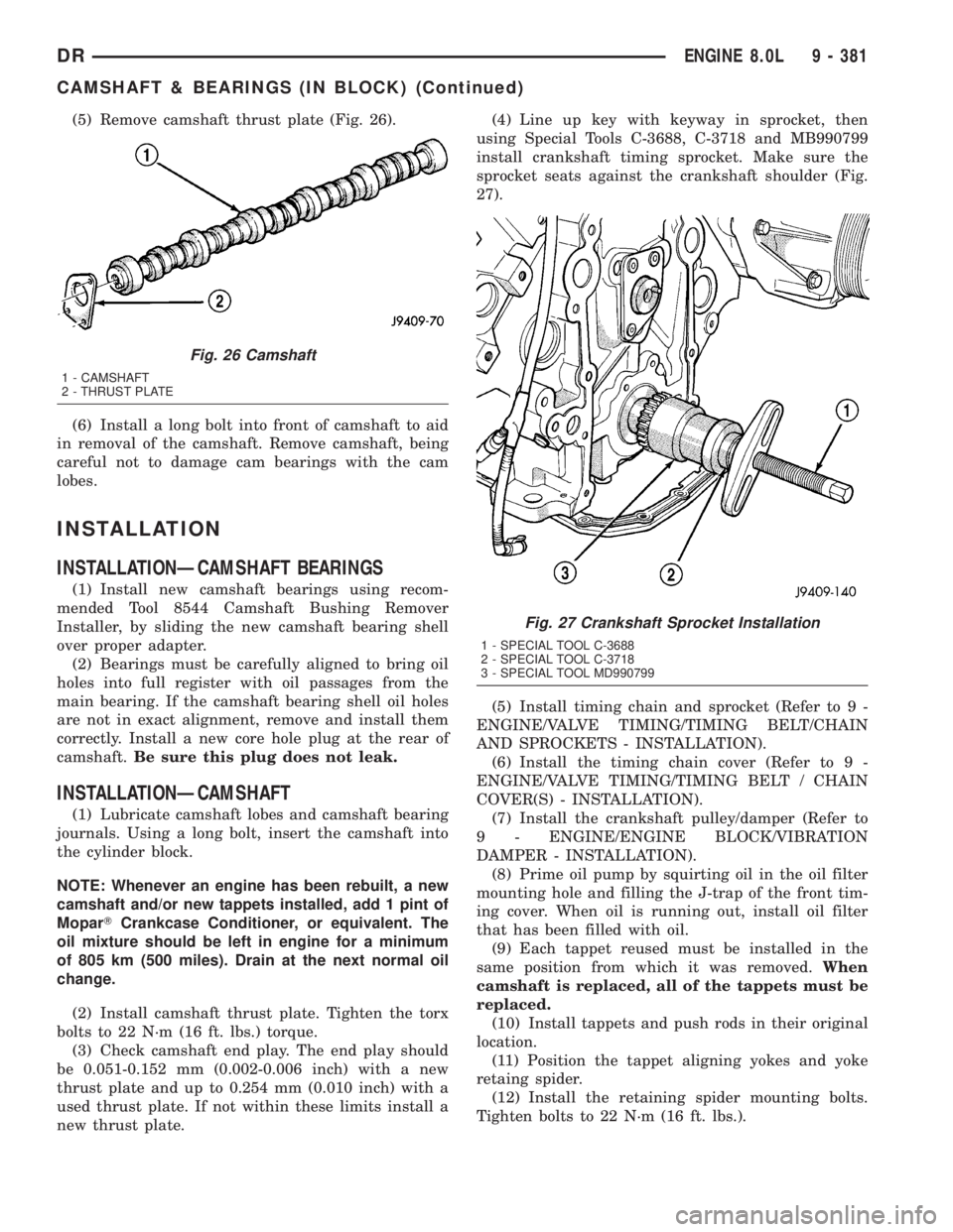
(5) Remove camshaft thrust plate (Fig. 26).
(6) Install a long bolt into front of camshaft to aid
in removal of the camshaft. Remove camshaft, being
careful not to damage cam bearings with the cam
lobes.
INSTALLATION
INSTALLATIONÐCAMSHAFT BEARINGS
(1) Install new camshaft bearings using recom-
mended Tool 8544 Camshaft Bushing Remover
Installer, by sliding the new camshaft bearing shell
over proper adapter.
(2) Bearings must be carefully aligned to bring oil
holes into full register with oil passages from the
main bearing. If the camshaft bearing shell oil holes
are not in exact alignment, remove and install them
correctly. Install a new core hole plug at the rear of
camshaft.Be sure this plug does not leak.
INSTALLATIONÐCAMSHAFT
(1) Lubricate camshaft lobes and camshaft bearing
journals. Using a long bolt, insert the camshaft into
the cylinder block.
NOTE: Whenever an engine has been rebuilt, a new
camshaft and/or new tappets installed, add 1 pint of
MoparTCrankcase Conditioner, or equivalent. The
oil mixture should be left in engine for a minimum
of 805 km (500 miles). Drain at the next normal oil
change.
(2) Install camshaft thrust plate. Tighten the torx
bolts to 22 N´m (16 ft. lbs.) torque.
(3) Check camshaft end play. The end play should
be 0.051-0.152 mm (0.002-0.006 inch) with a new
thrust plate and up to 0.254 mm (0.010 inch) with a
used thrust plate. If not within these limits install a
new thrust plate.(4) Line up key with keyway in sprocket, then
using Special Tools C-3688, C-3718 and MB990799
install crankshaft timing sprocket. Make sure the
sprocket seats against the crankshaft shoulder (Fig.
27).
(5) Install timing chain and sprocket (Refer to 9 -
ENGINE/VALVE TIMING/TIMING BELT/CHAIN
AND SPROCKETS - INSTALLATION).
(6) Install the timing chain cover (Refer to 9 -
ENGINE/VALVE TIMING/TIMING BELT / CHAIN
COVER(S) - INSTALLATION).
(7) Install the crankshaft pulley/damper (Refer to
9 - ENGINE/ENGINE BLOCK/VIBRATION
DAMPER - INSTALLATION).
(8) Prime oil pump by squirting oil in the oil filter
mounting hole and filling the J-trap of the front tim-
ing cover. When oil is running out, install oil filter
that has been filled with oil.
(9) Each tappet reused must be installed in the
same position from which it was removed.When
camshaft is replaced, all of the tappets must be
replaced.
(10) Install tappets and push rods in their original
location.
(11) Position the tappet aligning yokes and yoke
retaing spider.
(12) Install the retaining spider mounting bolts.
Tighten bolts to 22 N´m (16 ft. lbs.).
Fig. 26 Camshaft
1 - CAMSHAFT
2 - THRUST PLATE
Fig. 27 Crankshaft Sprocket Installation
1 - SPECIAL TOOL C-3688
2 - SPECIAL TOOL C-3718
3 - SPECIAL TOOL MD990799
DRENGINE 8.0L 9 - 381
CAMSHAFT & BEARINGS (IN BLOCK) (Continued)
Page 1631 of 2895
(13) Install the rocker arms (Refer to 9 - ENGINE/
CYLINDER HEAD/ROCKER ARM / ADJUSTER
ASSY - INSTALLATION).
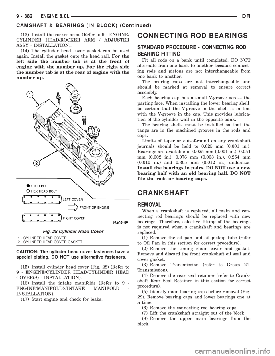
(14) The cylinder head cover gasket can be used
again. Install the gasket onto the head rail.For the
left side the number tab is at the front of
engine with the number up. For the right side
the number tab is at the rear of engine with the
number up.
CAUTION: The cylinder head cover fasteners have a
special plating. DO NOT use alternative fasteners.
(15) Install cylinder head cover (Fig. 28) (Refer to
9 - ENGINE/CYLINDER HEAD/CYLINDER HEAD
COVER(S) - INSTALLATION).
(16) Install the intake manifolds (Refer to 9 -
ENGINE/MANIFOLDS/INTAKE MANIFOLD -
INSTALLATION).
(17) Start engine and check for leaks.CONNECTING ROD BEARINGS
STANDARD PROCEDURE - CONNECTING ROD
BEARING FITTING
Fit all rods on a bank until completed. DO NOT
alternate from one bank to another, because connect-
ing rods and pistons are not interchangeable from
one bank to another.
The bearing caps are not interchangeable and
should be marked at removal to ensure correct
assembly.
Each bearing cap has a small V-groove across the
parting face. When installing the lower bearing shell,
be certain that the V-groove in the shell is in line
with the V-groove in the cap. This provides lubrica-
tion of the cylinder wall in the opposite bank.
The bearing shells must be installed so that the
tangs are in the machined grooves in the rods and
caps.
Limits of taper or out-of-round on any crankshaft
journals should be held to 0.025 mm (0.001 in.).
Bearings are available in 0.025 mm (0.001 in.), 0.051
mm (0.002 in.), 0.076 mm (0.003 in.), 0.254 mm
(0.010 in.) and 0.305 mm (0.012 in.) undersize.
Install the bearings in pairs. DO NOT use a new
bearing half with an old bearing half. DO NOT
file the rods or bearing caps.
CRANKSHAFT
REMOVAL
When a crankshaft is replaced, all main and con-
necting rod bearings should be replaced with new
bearings. Therefore, selective fitting of the bearings
is not required when a crankshaft and bearings are
replaced.
(1) Remove the oil pan and oil pickup tube (refer
to Oil Pan in this section for correct procedure).
(2) Remove the timing chain cover and gasket.
Remove and discard the front crankshaft oil seal and
cover gasket.
(3) Remove Transmission (refer to Group 21,
Transmission).
(4) Remove the rear seal retainer (refer to Crank-
shaft Rear Seal Retainer in this section for correct
procedure).
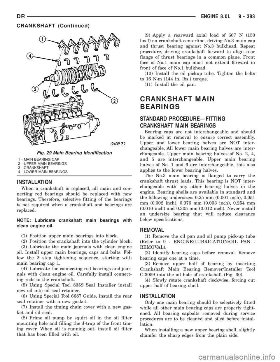
(5) Identify main bearing caps before removal (Fig.
29). Remove bearing caps and lower bearings one at
a time.
(6) Remove the connecting rod bearing caps.
(7) Lift the crankshaft straight out of the block.
(8) Remove the upper main bearings from the
block.
Fig. 28 Cylinder Head Cover
1 - CYLINDER HEAD COVER
2 - CYLINDER HEAD COVER GASKET
9 - 382 ENGINE 8.0LDR
CAMSHAFT & BEARINGS (IN BLOCK) (Continued)
Page 1632 of 2895
INSTALLATION
When a crankshaft is replaced, all main and con-
necting rod bearings should be replaced with new
bearings. Therefore, selective fitting of the bearings
is not required when a crankshaft and bearings are
replaced.
NOTE: Lubricate crankshaft main bearings with
clean engine oil.
(1) Position upper main bearings into block.
(2) Position the crankshaft into the cylinder block.
(3) Lubricate the main journals with clean engine
oil. Install upper main bearings, caps and bolts. Fol-
low the 2 step tightening sequence, starting with
main bearing cap 1.
(4) Lubricate the connecting rod bearings and jour-
nals with clean engine oil. Carefully install connect-
ing rods to the crankshaft.
(5) Using Special Tool 8359 Seal Installer install
new oil into oil seal retainer.
(6) Using Special Tool 6687 Guide, install the rear
seal retainer with a new gasket.
(7) Install the timing chain cover with a new gas-
ket and oil seal.
(8) Prime oil pump by squirt oil in the oil filter
mounting hole and filling the J-trap of the front tim-
ing cover. When oil is running out, install oil filter
that has been filled with oil.(9) Apply a rearward axial load of 667 N (150
lbs-f) on crankshaft centerline, driving No.3 main cap
and thrust bearing against No.3 bulkhead. Repeat
procedure, driving crankshaft forward to align rear
flange of thrust bearings in a common plane. Front
face of No.1 main cap must not extend forward in
front of face of No.1 bulkhead.
(10) Install the oil pickup tube. Tighten the bolts
to 16 N´m (144 in. lbs.) torque.
(11) Install the oil pan.
CRANKSHAFT MAIN
BEARINGS
STANDARD PROCEDUREÐFITTING
CRANKSHAFT MAIN BEARINGS
Bearing caps are not interchangeable and should
be marked at removal to ensure correct assembly.
Upper and lower bearing halves are NOT inter-
changeable. All lower main bearing halves are inter-
changeable. Upper main bearing halves of No. 2, 4,
and 5 are interchangeable. Upper main bearing
halves of No. 1 and 6 are interchangeable, this also
applies to the lower bearing halves.
The No.3 main bearing is flanged to carry the
crankshaft thrust loads. This bearing is NOT inter-
changeable with any other bearing halves in the
engine. Bearing shells are available in standard and
the following undersizes: 0.25 mm (0.001 inch), 0.051
mm (0.002 inch), 0.076 mm (0.003 inch), 0.254 mm
(0.010 inch) and 0.305 mm (0.012 inch). Never install
an undersize bearing that will reduce clearance
below specifications.
REMOVAL
(1) Remove the oil pan and oil pump pick-up tube
(Refer to 9 - ENGINE/LUBRICATION/OIL PAN -
REMOVAL).
(2) Identify bearing caps before removal. Remove
bearing caps one at a time.
(3) Remove upper half of bearing by inserting
Crankshaft Main Bearing Remover/Installer Tool
C-3059 into the oil hole of crankshaft (Fig. 30).
(4) Slowly rotate crankshaft clockwise, forcing out
upper half of bearing shell.
INSTALLATION
Only one main bearing should be selectively fitted
while all other main bearing caps are properly tight-
ened. All bearing capbolts removed during service
procedures are to be cleaned and oiled before instal-
lation.
When installing a new upper bearing shell, slightly
chamfer the sharp edges from the plain side.
Fig. 29 Main Bearing Identification
1 - MAIN BEARING CAP
2 - UPPER MAIN BEARINGS
3 - CRANKSHAFT
4 - LOWER MAIN BEARINGS
DRENGINE 8.0L 9 - 383
CRANKSHAFT (Continued)
Page 1639 of 2895
NOTE: Be sure position of rings does not change
during the following step.
(5) Immerse the piston head and rings in clean
engine oil. Slide Piston Ring Compressor Tool C-385
over the piston and tighten with the special wrench
(part of Tool C-385).
(6) Install connecting rod bolt protectors on rod
bolts, a long protector should be installed on the
numbered side of the connecting rod.
(7) Rotate crankshaft so that the connecting rod
journal is on the center of the cylinder bore in the
bottom dead center (BDC) position. Be sure connect-
ing rod and cylinder bore number are the same.
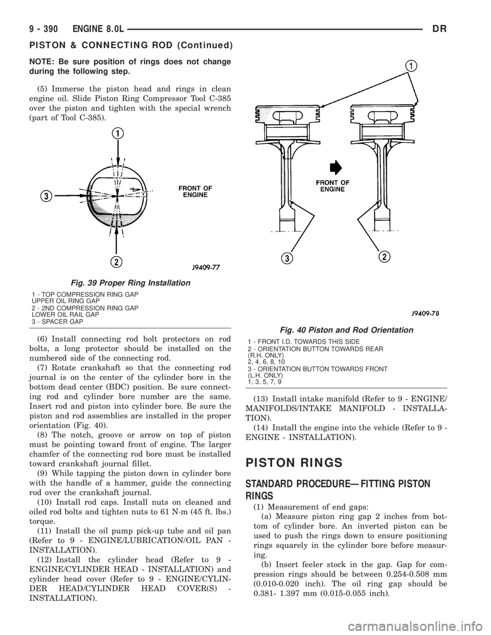
Insert rod and piston into cylinder bore. Be sure the
piston and rod assemblies are installed in the proper
orientation (Fig. 40).
(8) The notch, groove or arrow on top of piston
must be pointing toward front of engine. The larger
chamfer of the connecting rod bore must be installed
toward crankshaft journal fillet.
(9) While tapping the piston down in cylinder bore
with the handle of a hammer, guide the connecting
rod over the crankshaft journal.
(10) Install rod caps. Install nuts on cleaned and
oiled rod bolts and tighten nuts to 61 N´m (45 ft. lbs.)
torque.
(11) Install the oil pump pick-up tube and oil pan
(Refer to 9 - ENGINE/LUBRICATION/OIL PAN -
INSTALLATION).
(12) Install the cylinder head (Refer to 9 -
ENGINE/CYLINDER HEAD - INSTALLATION) and
cylinder head cover (Refer to 9 - ENGINE/CYLIN-
DER HEAD/CYLINDER HEAD COVER(S) -
INSTALLATION).(13) Install intake manifold (Refer to 9 - ENGINE/
MANIFOLDS/INTAKE MANIFOLD - INSTALLA-
TION).
(14) Install the engine into the vehicle (Refer to 9 -
ENGINE - INSTALLATION).
PISTON RINGS
STANDARD PROCEDUREÐFITTING PISTON
RINGS
(1) Measurement of end gaps:
(a) Measure piston ring gap 2 inches from bot-
tom of cylinder bore. An inverted piston can be
used to push the rings down to ensure positioning
rings squarely in the cylinder bore before measur-
ing.
(b) Insert feeler stock in the gap. Gap for com-
pression rings should be between 0.254-0.508 mm
(0.010-0.020 inch). The oil ring gap should be
0.381- 1.397 mm (0.015-0.055 inch).
Fig. 39 Proper Ring Installation
1 - TOP COMPRESSION RING GAP
UPPER OIL RING GAP
2 - 2ND COMPRESSION RING GAP
LOWER OIL RAIL GAP
3 - SPACER GAP
Fig. 40 Piston and Rod Orientation
1 - FRONT I.D. TOWARDS THIS SIDE
2 - ORIENTATION BUTTON TOWARDS REAR
(R.H. ONLY)
2, 4, 6, 8, 10
3 - ORIENTATION BUTTON TOWARDS FRONT
(L.H. ONLY)
1, 3, 5, 7, 9
9 - 390 ENGINE 8.0LDR
PISTON & CONNECTING ROD (Continued)
Page 1645 of 2895
DIAGNOSIS AND TESTINGÐENGINE OIL
PRESSURE
(1) Remove oil pressure sending unit.
(2) Install Oil Pressure Line and Gauge Tool
C-3292. Start engine and record pressure. (Refer to 9
- ENGINE - SPECIFICATIONS).
OIL
STANDARD PROCEDURE - ENGINE OIL
OIL LEVEL INDICATOR (DIPSTICK)
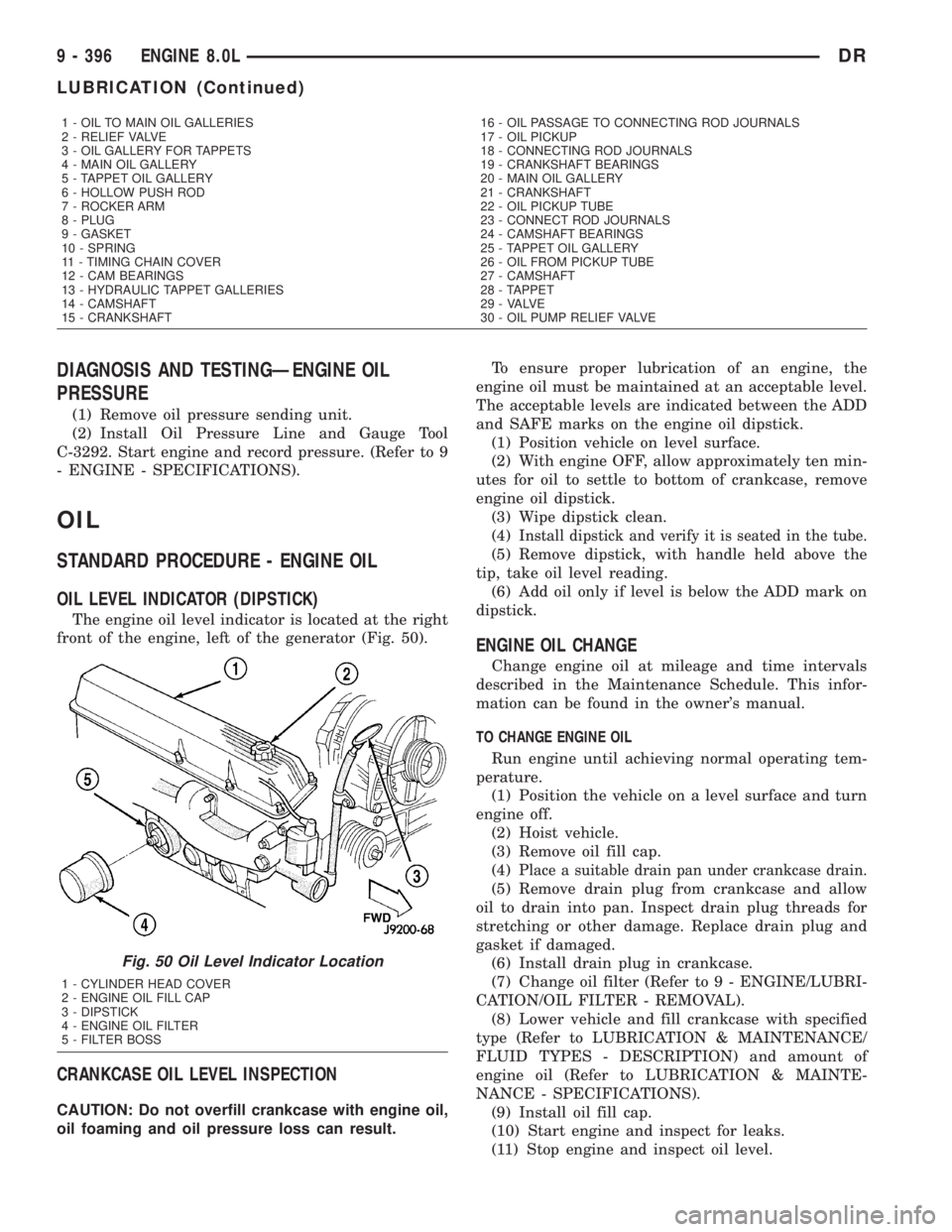
The engine oil level indicator is located at the right
front of the engine, left of the generator (Fig. 50).
CRANKCASE OIL LEVEL INSPECTION
CAUTION: Do not overfill crankcase with engine oil,
oil foaming and oil pressure loss can result.To ensure proper lubrication of an engine, the
engine oil must be maintained at an acceptable level.
The acceptable levels are indicated between the ADD
and SAFE marks on the engine oil dipstick.
(1) Position vehicle on level surface.
(2) With engine OFF, allow approximately ten min-
utes for oil to settle to bottom of crankcase, remove
engine oil dipstick.
(3) Wipe dipstick clean.
(4)
Install dipstick and verify it is seated in the tube.
(5) Remove dipstick, with handle held above the
tip, take oil level reading.
(6) Add oil only if level is below the ADD mark on
dipstick.
ENGINE OIL CHANGE
Change engine oil at mileage and time intervals
described in the Maintenance Schedule. This infor-
mation can be found in the owner's manual.
TO CHANGE ENGINE OIL
Run engine until achieving normal operating tem-
perature.
(1) Position the vehicle on a level surface and turn
engine off.
(2) Hoist vehicle.
(3) Remove oil fill cap.
(4)
Place a suitable drain pan under crankcase drain.
(5) Remove drain plug from crankcase and allow
oil to drain into pan. Inspect drain plug threads for
stretching or other damage. Replace drain plug and
gasket if damaged.
(6) Install drain plug in crankcase.
(7) Change oil filter (Refer to 9 - ENGINE/LUBRI-
CATION/OIL FILTER - REMOVAL).
(8) Lower vehicle and fill crankcase with specified
type (Refer to LUBRICATION & MAINTENANCE/
FLUID TYPES - DESCRIPTION) and amount of
engine oil (Refer to LUBRICATION & MAINTE-
NANCE - SPECIFICATIONS).
(9) Install oil fill cap.
(10) Start engine and inspect for leaks.
(11) Stop engine and inspect oil level.
1 - OIL TO MAIN OIL GALLERIES
2 - RELIEF VALVE
3 - OIL GALLERY FOR TAPPETS
4 - MAIN OIL GALLERY
5 - TAPPET OIL GALLERY
6 - HOLLOW PUSH ROD
7 - ROCKER ARM
8 - PLUG
9 - GASKET
10 - SPRING
11 - TIMING CHAIN COVER
12 - CAM BEARINGS
13 - HYDRAULIC TAPPET GALLERIES
14 - CAMSHAFT
15 - CRANKSHAFT16 - OIL PASSAGE TO CONNECTING ROD JOURNALS
17 - OIL PICKUP
18 - CONNECTING ROD JOURNALS
19 - CRANKSHAFT BEARINGS
20 - MAIN OIL GALLERY
21 - CRANKSHAFT
22 - OIL PICKUP TUBE
23 - CONNECT ROD JOURNALS
24 - CAMSHAFT BEARINGS
25 - TAPPET OIL GALLERY
26 - OIL FROM PICKUP TUBE
27 - CAMSHAFT
28 - TAPPET
29 - VALVE
30 - OIL PUMP RELIEF VALVE
Fig. 50 Oil Level Indicator Location
1 - CYLINDER HEAD COVER
2 - ENGINE OIL FILL CAP
3 - DIPSTICK
4 - ENGINE OIL FILTER
5 - FILTER BOSS
9 - 396 ENGINE 8.0LDR
LUBRICATION (Continued)
Page 1650 of 2895
(7) Using a new pressure relief valve gasket,
install the relief valve plug. Tighten the plug to 20
N´m (15 ft. lbs.) torque.
(8) Install oil filter that has been filled with oil.
INTAKE MANIFOLD
DESCRIPTION
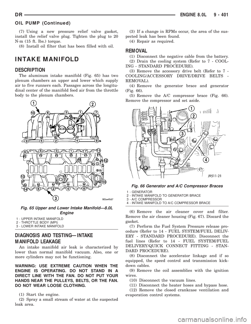
The aluminum intake manifold (Fig. 65) has two
plenum chambers an upper and lower which supply
air to five runners each. Passages across the longitu-
dinal center of the manifold feed air from the throttle
body to the plenum chambers.
DIAGNOSIS AND TESTINGÐINTAKE
MANIFOLD LEAKAGE
An intake manifold air leak is characterized by
lower than normal manifold vacuum. Also, one or
more cylinders may not be functioning.
WARNING: USE EXTREME CAUTION WHEN THE
ENGINE IS OPERATING. DO NOT STAND IN A
DIRECT LINE WITH THE FAN. DO NOT PUT YOUR
HANDS NEAR THE PULLEYS, BELTS, OR THE FAN.
DO NOT WEAR LOOSE CLOTHING.
(1) Start the engine.
(2) Spray a small stream of water at the suspected
leak area.(3) If a change in RPMs occur, the area of the sus-
pected leak has been found.
(4) Repair as required.
REMOVAL
(1) Disconnect the negative cable from the battery.
(2) Drain the cooling system (Refer to 7 - COOL-
ING - STANDARD PROCEDURE).
(3) Remove the accessory drive belt (Refer to 7 -
COOLING/ACCESSORY DRIVE/DRIVE BELTS -
REMOVAL).
(4) Remove the generator brace and generator
(Fig. 66).
(5) Remove the A/C compressor brace (Fig. 66).
Remove the compressor and set aside.
(6) Remove the air cleaner cover and filter.
Remove the air cleaner housing (Fig. 67). Discard the
gasket.
(7) Perform the Fuel System Pressure release pro-
cedure (Refer to 14 - FUEL SYSTEM/FUEL DELIV-
ERY - STANDARD PROCEDURE). Disconnect the
fuel lines (Refer to 14 - FUEL SYSTEM/FUEL
DELIVERY/QUICK CONNECT FITTING - STAN-
DARD PROCEDURE).
(8) Disconnect the accelerator linkage and if so
equipped, the speed control and transmission kick-
down cables.
(9) Remove the coil assemblies with the ignition
wires.
(10) Disconnect the vacuum lines.
(11) Disconnect the heater hoses and bypass hose.
(12) Remove the closed crankcase ventilation and
evaporation control systems.
Fig. 65 Upper and Lower Intake ManifoldÐ8.0L
Engine
1 - UPPER INTAKE MANIFOLD
2 - THROTTLE BODY (MPI)
3 - LOWER INTAKE MANIFOLD
Fig. 66 Generator and A/C Compressor Braces
1 - GENERATOR
2 - INTAKE MANIFOLD TO GENERATOR BRACE
3 - A/C COMPRESSOR
4 - INTAKE MANIFOLD TO A/C COMPRESSOR BRACE
DRENGINE 8.0L 9 - 401
OIL PUMP (Continued)
Page 1652 of 2895

(2) Insert MopartGEN II Silicone Rubber Adhe-
sive Sealant, or equivalent, into the four corner joints
an excessive amount of sealant is not required to
ensure a leak proof seal. However, an excessive
amount of sealant may reduce the effectiveness of
the flange gasket. The sealant should be approxi-
mately 5 mm (0.2 in.) in diameter. (Fig. 70).
(3) Position the cross-over gaskets and press firmly
onto the block (Fig. 70).BE SURE THE BLOCK IS
OIL FREE..
(4) The lower intake manifold MUST be installed
within 3 minutes of sealant application. Carefully
lower intake manifold into position on the cylinder
block and heads. After intake manifold is in place,
inspect to make sure seals and gaskets are in place.
Finger start all the lower intake bolts.
(5) Tighten the lower intake manifold bolts in
sequence to 54 N´m (40 ft. lbs.) torque (Fig. 69).
Recheck all bolts are tightened to 54 N´m (40 ft. lbs.)
torque.
(6) Using a new gasket, position the upper intake
manifold onto the lower intake manifold.
(7) Finger start all bolts, alternate one side to the
other.
(8) Tighten upper intake manifold bolts in
sequence to 22 N´m (16 ft. lbs.) torque (Fig. 68).
(9) Using a new gasket, install the throttle body
onto the upper intake manifold. Tighten the bolts to
23 N´m (200 in. lbs.) torque.
(10) Install closed crankcase ventilation and evap-
oration control systems.
(11) Connect the heater hoses and bypass hose.
(12) Connect the vacuum lines.
(13) Install the coil assemblies and the ignition
wires.
(14) Connect the accelerator linkage and if so
equipped, the speed control and transmission kick-
down cables.(15) Install the fuel lines (Refer to 14 - FUEL SYS-
TEM/FUEL DELIVERY/QUICK CONNECT FIT-
TING - STANDARD PROCEDURE).
(16) Using a new gasket, install the air cleaner
housing. Tighten the nuts to 11 N´m (96 in. lbs.)
torque. Install the air cleaner filter and cover.
(17) Install the A/C compressor (Refer to 24 -
HEATING & AIR CONDITIONING/PLUMBING/A/C
COMPRESSOR - INSTALLATION). Position the com-
pressor brace and install the bolts. Tighten the brace
bolts to 41 N´m (30 ft. lbs.) torque.
(18) Install the generator (Refer to 8 - ELECTRI-
CAL/CHARGING/GENERATOR - INSTALLATION).
Position the generator brace and install the bolts.
Tighten the brace bolts to 41 N´m (30 ft. lbs.) torque.
(19) Install the accessory drive belt (Refer to 7 -
COOLING/ACCESSORY DRIVE/DRIVE BELTS -
INSTALLATION).
(20) Fill cooling system (Refer to 7 - COOLING -
STANDARD PROCEDURE).
(21) Connect the negative cable to the battery.
(22) Start engine check for leaks.
EXHAUST MANIFOLD
DESCRIPTION
Engine exhaust manifolds (Fig. 72) are made of
high molybdenum ductile cast iron. A special ribbed
design helps control permanent dimensional changes
during heat cycles.
OPERATION
The exhaust manifolds collect the engine exhaust
exiting the combustion chambers, then channels the
exhaust gases to the exhaust pipes attached to the
manifolds.
Fig. 71 Intake Manifold Flange
1 - LOCATOR DOWELS
2 - INTAKE MANIFOLD GASKETS
3 - LOCATOR DOWELS
Fig. 72 Exhaust ManifoldÐ8.0L Engine
1 - EXHAUST MANIFOLD
DRENGINE 8.0L 9 - 403
INTAKE MANIFOLD (Continued)
Page 1670 of 2895
(3)Pre-lube the turbocharger.Pour 50 to 60 cc
(2 to 3 oz.) clean engine oil in the oil supply line fit-
ting. Carefully rotate the turbocharger impeller by
hand to distribute the oil thoroughly.
(4) Install and tighten the oil supply line to 24
N´m (18 ft. lbs.) torque.
(5) Position the charge air cooler inlet pipe to the
turbocharger. With the clamp in position, tighten the
clamp nut to 11 N´m (95 in. lbs.) torque.
(6) Position the air inlet hose to the turbocharger
(Fig. 18). Tighten the clamp to 11 N´m (95 in. lbs.)
torque.
(7) Raise vehicle on hoist.
(8) Connect the exhaust pipe to the turbocharger
and tighten the bolts to 34 N´m (25 ft. lbs.) torque.
(9) Lower the vehicle.
(10) Connect the battery negative cables.
(11) Start the engine to check for leaks.
CHARGE AIR COOLER AND
PLUMBING
DESCRIPTION
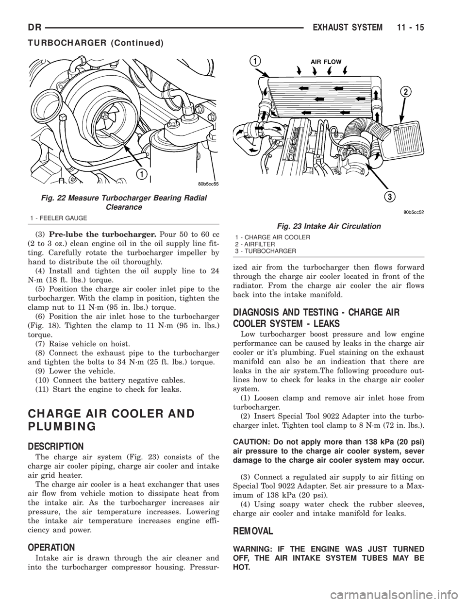
The charge air system (Fig. 23) consists of the
charge air cooler piping, charge air cooler and intake
air grid heater.
The charge air cooler is a heat exchanger that uses
air flow from vehicle motion to dissipate heat from
the intake air. As the turbocharger increases air
pressure, the air temperature increases. Lowering
the intake air temperature increases engine effi-
ciency and power.
OPERATION
Intake air is drawn through the air cleaner and
into the turbocharger compressor housing. Pressur-ized air from the turbocharger then flows forward
through the charge air cooler located in front of the
radiator. From the charge air cooler the air flows
back into the intake manifold.
DIAGNOSIS AND TESTING - CHARGE AIR
COOLER SYSTEM - LEAKS
Low turbocharger boost pressure and low engine
performance can be caused by leaks in the charge air
cooler or it's plumbing. Fuel staining on the exhaust
manifold can also be an indication that there are
leaks in the air system.The following procedure out-
lines how to check for leaks in the charge air cooler
system.
(1) Loosen clamp and remove air inlet hose from
turbocharger.
(2)
Insert Special Tool 9022 Adapter into the turbo-
charger inlet. Tighten tool clamp to 8 N´m (72 in. lbs.).
CAUTION: Do not apply more than 138 kPa (20 psi)
air pressure to the charge air cooler system, sever
damage to the charge air cooler system may occur.
(3) Connect a regulated air supply to air fitting on
Special Tool 9022 Adapter. Set air pressure to a Max-
imum of 138 kPa (20 psi).
(4) Using soapy water check the rubber sleeves,
charge air cooler and intake manifold for leaks.
REMOVAL
WARNING: IF THE ENGINE WAS JUST TURNED
OFF, THE AIR INTAKE SYSTEM TUBES MAY BE
HOT.
Fig. 22 Measure Turbocharger Bearing Radial
Clearance
1 - FEELER GAUGE
Fig. 23 Intake Air Circulation
1 - CHARGE AIR COOLER
2 - AIRFILTER
3 - TURBOCHARGER
DREXHAUST SYSTEM 11 - 15
TURBOCHARGER (Continued)