2003 DODGE RAM oil change
[x] Cancel search: oil changePage 2326 of 2895
(15) Check and adjust front and rear bands if nec-
essary.
(16) Connect solenoid case connector wires.
(17) Install the transmission range sensor.
(18) Install oil pan and new gasket. Tighten pan
bolts to 17 N´m (13 ft. lbs.) torque.
(19) Lower vehicle and fill transmission with
MopartATF +4, Automatic Transmission fluid.
(20) Check and adjust gearshift and throttle valve
cables, if necessary.
ADJUSTMENTS - VALVE BODY
CONTROL PRESSURE ADJUSTMENTS
There are two control pressure adjustments on the
valve body;
²Line Pressure
²Throttle Pressure
Line and throttle pressures are interdependent
because each affects shift quality and timing. As a
result, both adjustments must be performed properly
and in the correct sequence. Adjust line pressure first
and throttle pressure last.
LINE PRESSURE ADJUSTMENT
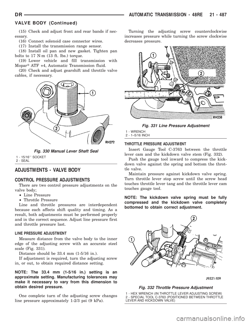
Measure distance from the valve body to the inner
edge of the adjusting screw with an accurate steel
scale (Fig. 331).
Distance should be 33.4 mm (1-5/16 in.).
If adjustment is required, turn the adjusting screw
in, or out, to obtain required distance setting.
NOTE: The 33.4 mm (1-5/16 in.) setting is an
approximate setting. Manufacturing tolerances may
make it necessary to vary from this dimension to
obtain desired pressure.
One complete turn of the adjusting screw changes
line pressure approximately 1-2/3 psi (9 kPa).Turning the adjusting screw counterclockwise
increases pressure while turning the screw clockwise
decreases pressure.
THROTTLE PRESSURE ADJUSTMENT
Insert Gauge Tool C-3763 between the throttle
lever cam and the kickdown valve stem (Fig. 332).
Push the gauge tool inward to compress the kick-
down valve against the spring and bottom the throt-
tle valve.
Maintain pressure against kickdown valve spring.
Turn throttle lever stop screw until the screw head
touches throttle lever tang and the throttle lever cam
touches gauge tool.
NOTE: The kickdown valve spring must be fully
compressed and the kickdown valve completely
bottomed to obtain correct adjustment.
Fig. 330 Manual Lever Shaft Seal
1 - 15/1688SOCKET
2 - SEAL
Fig. 331 Line Pressure Adjustment
1 - WRENCH
2 - 1±5/16 INCH
Fig. 332 Throttle Pressure Adjustment
1 - HEX WRENCH (IN THROTTLE LEVER ADJUSTING SCREW)
2 - SPECIAL TOOL C-3763 (POSITIONED BETWEEN THROTTLE
LEVER AND KICKDOWN VALVE)
DRAUTOMATIC TRANSMISSION - 48RE 21 - 487
VALVE BODY (Continued)
Page 2383 of 2895
(2) Place replacement filter in position on valve
body and into the oil pump.
(3) Install screw to hold filter to valve body (Fig.
67). Tighten screw to 4.5 N´m (40 in. lbs.) torque.
(4) Install new cooler return filter onto the trans-
mission, if necessary. Torque the filter to 14.12 N´m
(125 in.lbs.).
(5) Place bead of MopartRTV sealant onto the
transmission case sealing surface.
(6) Place pan in position on transmission.
(7) Install bolts to hold pan to transmission.
Tighten bolts to 11.8 N´m (105 in. lbs.) torque.
(8) Lower vehicle and fill transmission with
MopartATF +4.
STANDARD PROCEDURE - TRANSMISSION
FILL
To avoid overfilling transmission after a fluid
change or overhaul, perform the following procedure:
(1) Remove dipstick and insert clean funnel in
transmission fill tube.
(2) Add following initial quantity of MopartAT F
+4 to transmission:
(a) If only fluid and filter were changed, add10
pints (5 quarts)of ATF +4 to transmission.
(b) If transmission was completely overhauled
and the torque converter was replaced or drained,
add24 pints (12 quarts)of ATF +4 to transmis-
sion.
(3) Check the transmission fluid (Refer to 21 -
TRANSMISSION/AUTOMATIC - RFE/FLUID -
STANDARD PROCEDURE) and adjust as required.
GEARSHIFT CABLE
DIAGNOSIS AND TESTING - GEARSHIFT
CABLE
(1) Engine starts must be possible with shift lever
in PARK or NEUTRAL positions only. Engine starts
must not be possible in any other gear position.
(2) With the shift lever in the:
(a) PARK position - Apply upward force on the
shift arm and remove pressure. Engine starts must
be possible.
(b) PARK position - Apply downward force on
the shift arm and remove pressure. Engine starts
must be possible.
(c) NEUTRAL position - Normal position. Engine
starts must be possible.
(d) NEUTRAL position - Engine running and
brakes applied, apply upward force on the shift
arm. Transmission shall not be able to shift from
neutral to reverse.
REMOVAL
(1) Shift transmission into PARK.
(2) Raise vehicle.
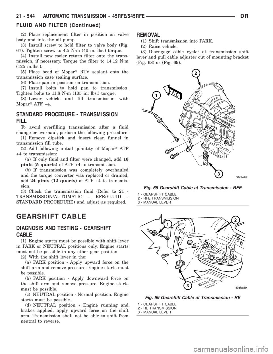
(3) Disengage cable eyelet at transmission shift
lever and pull cable adjuster out of mounting bracket
(Fig. 68) or (Fig. 69).
Fig. 68 Gearshift Cable at Transmission - RFE
1 - GEARSHIFT CABLE
2 - RFE TRANSMISSION
3 - MANUAL LEVER
Fig. 69 Gearshift Cable at Transmission - RE
1 - GEARSHIFT CABLE
2 - RE TRANSMISSION
3 - MANUAL LEVER
21 - 544 AUTOMATIC TRANSMISSION - 45RFE/545RFEDR
FLUID AND FILTER (Continued)
Page 2419 of 2895
control switch is in the OFF position, the clutch will
engage after the shift to third gear.
The TCM controls the torque converter by way of
internal logic software. The programming of the soft-
ware provides the TCM with control over the L/R-CC
Solenoid. There are four output logic states that can
be applied as follows:
²No EMCC
²Partial EMCC
²Full EMCC
²Gradual-to-no EMCC
NO EMCC
Under No EMCC conditions, the L/R Solenoid is
OFF. There are several conditions that can result in
NO EMCC operations. No EMCC can be initiated
due to a fault in the transmission or because the
TCM does not see the need for EMCC under current
driving conditions.
PARTIAL EMCC
Partial EMCC operation modulates the L/R Sole-
noid (duty cycle) to obtain partial torque converter
clutch application. Partial EMCC operation is main-
tained until Full EMCC is called for and actuated.
During Partial EMCC some slip does occur. Partial
EMCC will usually occur at low speeds, low load and
light throttle situations.
FULL EMCC
During Full EMCC operation, the TCM increases
the L/R Solenoid duty cycle to full ON after Partial
EMCC control brings the engine speed within thedesired slip range of transmission input speed rela-
tive to engine rpm.
GRADUAL-TO-NO EMCC
This operation is to soften the change from Full or
Partial EMCC to No EMCC. This is done at mid-
throttle by decreasing the L/R Solenoid duty cycle.
REMOVAL
(1) Remove transmission and torque converter
from vehicle.
(2) Place a suitable drain pan under the converter
housing end of the transmission.
CAUTION: Verify that transmission is secure on the
lifting device or work surface, the center of gravity
of the transmission will shift when the torque con-
verter is removed creating an unstable condition.
The torque converter is a heavy unit. Use caution
when separating the torque converter from the
transmission.
(3) Pull the torque converter forward until the cen-
ter hub clears the oil pump seal.
(4) Separate the torque converter from the trans-
mission.
INSTALLATION
Check converter hub and drive flats for sharp
edges, burrs, scratches, or nicks. Polish the hub and
flats with 320/400 grit paper or crocus cloth if neces-
sary. Verify that the converter hub o-ring is properly
installed and is free from debris. The hub must be
smooth to avoid damaging the pump seal at installa-
tion.
(1) Lubricate oil pump seal lip with transmission
fluid.
(2) Place torque converter in position on transmis-
sion.
CAUTION: Do not damage oil pump seal or con-
verter hub o-ring while inserting torque converter
into the front of the transmission.
(3) Align torque converter to oil pump seal open-
ing.
(4) Insert torque converter hub into oil pump.
(5) While pushing torque converter inward, rotate
converter until converter is fully seated in the oil
pump gears.
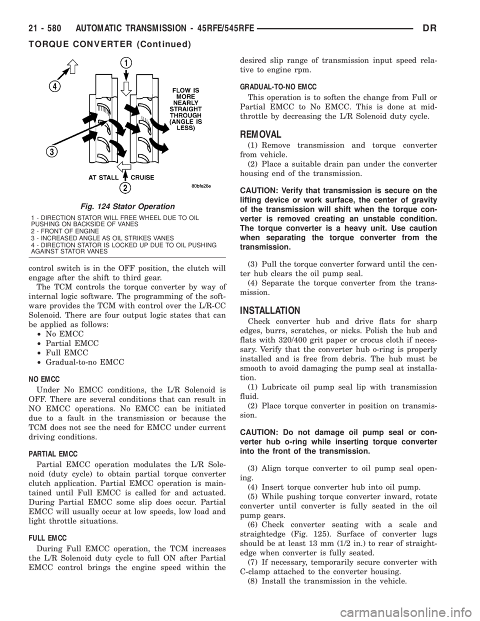
(6) Check converter seating with a scale and
straightedge (Fig. 125). Surface of converter lugs
should be at least 13 mm (1/2 in.) to rear of straight-
edge when converter is fully seated.
(7) If necessary, temporarily secure converter with
C-clamp attached to the converter housing.
(8) Install the transmission in the vehicle.
Fig. 124 Stator Operation
1 - DIRECTION STATOR WILL FREE WHEEL DUE TO OIL
PUSHING ON BACKSIDE OF VANES
2 - FRONT OF ENGINE
3 - INCREASED ANGLE AS OIL STRIKES VANES
4 - DIRECTION STATOR IS LOCKED UP DUE TO OIL PUSHING
AGAINST STATOR VANES
21 - 580 AUTOMATIC TRANSMISSION - 45RFE/545RFEDR
TORQUE CONVERTER (Continued)
Page 2428 of 2895
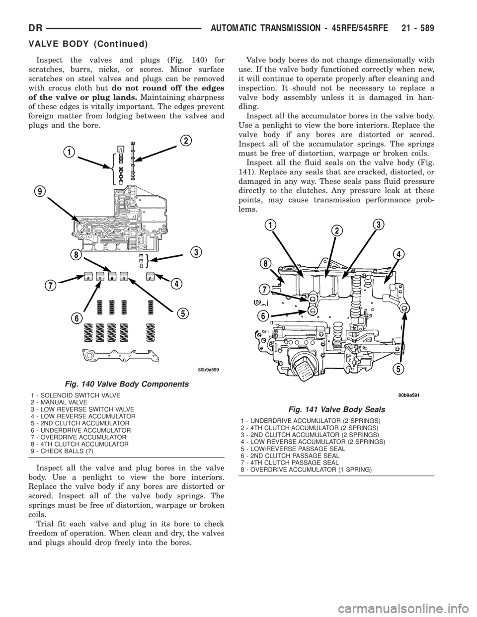
Inspect the valves and plugs (Fig. 140) for
scratches, burrs, nicks, or scores. Minor surface
scratches on steel valves and plugs can be removed
with crocus cloth butdo not round off the edges
of the valve or plug lands.Maintaining sharpness
of these edges is vitally important. The edges prevent
foreign matter from lodging between the valves and
plugs and the bore.
Inspect all the valve and plug bores in the valve
body. Use a penlight to view the bore interiors.
Replace the valve body if any bores are distorted or
scored. Inspect all of the valve body springs. The
springs must be free of distortion, warpage or broken
coils.
Trial fit each valve and plug in its bore to check
freedom of operation. When clean and dry, the valves
and plugs should drop freely into the bores.Valve body bores do not change dimensionally with
use. If the valve body functioned correctly when new,
it will continue to operate properly after cleaning and
inspection. It should not be necessary to replace a
valve body assembly unless it is damaged in han-
dling.
Inspect all the accumulator bores in the valve body.
Use a penlight to view the bore interiors. Replace the
valve body if any bores are distorted or scored.
Inspect all of the accumulator springs. The springs
must be free of distortion, warpage or broken coils.
Inspect all the fluid seals on the valve body (Fig.
141). Replace any seals that are cracked, distorted, or
damaged in any way. These seals pass fluid pressure
directly to the clutches. Any pressure leak at these
points, may cause transmission performance prob-
lems.
Fig. 140 Valve Body Components
1 - SOLENOID SWITCH VALVE
2 - MANUAL VALVE
3 - LOW REVERSE SWITCH VALVE
4 - LOW REVERSE ACCUMULATOR
5 - 2ND CLUTCH ACCUMULATOR
6 - UNDERDRIVE ACCUMULATOR
7 - OVERDRIVE ACCUMULATOR
8 - 4TH CLUTCH ACCUMULATOR
9 - CHECK BALLS (7)
Fig. 141 Valve Body Seals
1 - UNDERDRIVE ACCUMULATOR (2 SPRINGS)
2 - 4TH CLUTCH ACCUMULATOR (2 SPRINGS)
3 - 2ND CLUTCH ACCUMULATOR (2 SPRINGS)
4 - LOW REVERSE ACCUMULATOR (2 SPRINGS)
5 - LOW/REVERSE PASSAGE SEAL
6 - 2ND CLUTCH PASSAGE SEAL
7 - 4TH CLUTCH PASSAGE SEAL
8 - OVERDRIVE ACCUMULATOR (1 SPRING)
DRAUTOMATIC TRANSMISSION - 45RFE/545RFE 21 - 589
VALVE BODY (Continued)
Page 2791 of 2895
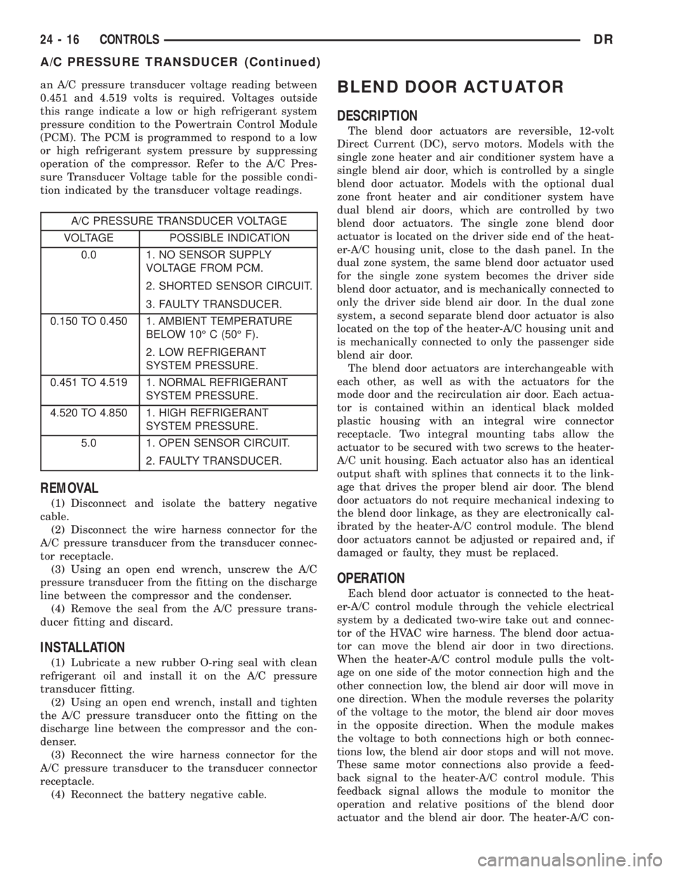
an A/C pressure transducer voltage reading between
0.451 and 4.519 volts is required. Voltages outside
this range indicate a low or high refrigerant system
pressure condition to the Powertrain Control Module
(PCM). The PCM is programmed to respond to a low
or high refrigerant system pressure by suppressing
operation of the compressor. Refer to the A/C Pres-
sure Transducer Voltage table for the possible condi-
tion indicated by the transducer voltage readings.
A/C PRESSURE TRANSDUCER VOLTAGE
VOLTAGE POSSIBLE INDICATION
0.0 1. NO SENSOR SUPPLY
VOLTAGE FROM PCM.
2. SHORTED SENSOR CIRCUIT.
3. FAULTY TRANSDUCER.
0.150 TO 0.450 1. AMBIENT TEMPERATURE
BELOW 10É C (50É F).
2. LOW REFRIGERANT
SYSTEM PRESSURE.
0.451 TO 4.519 1. NORMAL REFRIGERANT
SYSTEM PRESSURE.
4.520 TO 4.850 1. HIGH REFRIGERANT
SYSTEM PRESSURE.
5.0 1. OPEN SENSOR CIRCUIT.
2. FAULTY TRANSDUCER.
REMOVAL
(1) Disconnect and isolate the battery negative
cable.
(2) Disconnect the wire harness connector for the
A/C pressure transducer from the transducer connec-
tor receptacle.
(3) Using an open end wrench, unscrew the A/C
pressure transducer from the fitting on the discharge
line between the compressor and the condenser.
(4) Remove the seal from the A/C pressure trans-
ducer fitting and discard.
INSTALLATION
(1) Lubricate a new rubber O-ring seal with clean
refrigerant oil and install it on the A/C pressure
transducer fitting.
(2) Using an open end wrench, install and tighten
the A/C pressure transducer onto the fitting on the
discharge line between the compressor and the con-
denser.
(3) Reconnect the wire harness connector for the
A/C pressure transducer to the transducer connector
receptacle.
(4) Reconnect the battery negative cable.
BLEND DOOR ACTUATOR
DESCRIPTION
The blend door actuators are reversible, 12-volt
Direct Current (DC), servo motors. Models with the
single zone heater and air conditioner system have a
single blend air door, which is controlled by a single
blend door actuator. Models with the optional dual
zone front heater and air conditioner system have
dual blend air doors, which are controlled by two
blend door actuators. The single zone blend door
actuator is located on the driver side end of the heat-
er-A/C housing unit, close to the dash panel. In the
dual zone system, the same blend door actuator used
for the single zone system becomes the driver side
blend door actuator, and is mechanically connected to
only the driver side blend air door. In the dual zone
system, a second separate blend door actuator is also
located on the top of the heater-A/C housing unit and
is mechanically connected to only the passenger side
blend air door.
The blend door actuators are interchangeable with
each other, as well as with the actuators for the
mode door and the recirculation air door. Each actua-
tor is contained within an identical black molded
plastic housing with an integral wire connector
receptacle. Two integral mounting tabs allow the
actuator to be secured with two screws to the heater-
A/C unit housing. Each actuator also has an identical
output shaft with splines that connects it to the link-
age that drives the proper blend air door. The blend
door actuators do not require mechanical indexing to
the blend door linkage, as they are electronically cal-
ibrated by the heater-A/C control module. The blend
door actuators cannot be adjusted or repaired and, if
damaged or faulty, they must be replaced.
OPERATION
Each blend door actuator is connected to the heat-
er-A/C control module through the vehicle electrical
system by a dedicated two-wire take out and connec-
tor of the HVAC wire harness. The blend door actua-
tor can move the blend air door in two directions.
When the heater-A/C control module pulls the volt-
age on one side of the motor connection high and the
other connection low, the blend air door will move in
one direction. When the module reverses the polarity
of the voltage to the motor, the blend air door moves
in the opposite direction. When the module makes
the voltage to both connections high or both connec-
tions low, the blend air door stops and will not move.
These same motor connections also provide a feed-
back signal to the heater-A/C control module. This
feedback signal allows the module to monitor the
operation and relative positions of the blend door
actuator and the blend air door. The heater-A/C con-
24 - 16 CONTROLSDR
A/C PRESSURE TRANSDUCER (Continued)
Page 2814 of 2895
(7) Evacuate the refrigerant system. (Refer to 24 -
HEATING & AIR CONDITIONING/PLUMBING -
STANDARD PROCEDURE - REFRIGERANT SYS-
TEM EVACUATE)
(8) Charge the refrigerant system. (Refer to 24 -
HEATING & AIR CONDITIONING/PLUMBING -
STANDARD PROCEDURE - REFRIGERANT SYS-
TEM CHARGE)
INSTALLATION - 5.9L DIESEL ENGINE
WARNING: REVIEW THE WARNINGS AND CAU-
TIONS IN THE FRONT OF THIS SECTION BEFORE
PERFORMING THE FOLLOWING OPERATION.
(Refer to 24 - HEATING & AIR CONDITIONING/
PLUMBING - WARNING) (Refer to 24 - HEATING &
AIR CONDITIONING/PLUMBING - CAUTION)(Refer to
24 - HEATING & AIR CONDITIONING/PLUMBING -
CAUTION - REFRIGERANT HOSES/LINES/TUBES
PRECAUTIONS)
NOTE: If a replacement compressor is being
installed, be certain to check the refrigerant oil
level. (Refer to 24 - HEATING & AIR CONDITIONING/
PLUMBING/REFRIGERANT OIL - STANDARD PRO-
CEDURE) Use only refrigerant oil of the type
recommended for the compressor in the vehicle.
(Refer to 24 - HEATING & AIR CONDITIONING/
PLUMBING/REFRIGERANT OIL - DESCRIPTION)
(1) Install the compressor to the mounting bracket.
Tighten the four mounting bolts to 24 N´m (210 in.
lbs.).
(2) Remove the tape or plugs from all of the
opened refrigerant line fittings. Install the suction
and discharge line manifold to the compressor. (Refer
to 24 - HEATING & AIR CONDITIONING/PLUMB-
ING/A/C SUCTION AND DISCHARGE LINE -
INSTALLATION)
(3) Install the serpentine drive belt(Refer to 7 -
COOLING/ACCESSORY DRIVE/DRIVE BELTS -
INSTALLATION).
(4) Plug in the compressor clutch coil wire harness
connector.
(5) Connect the battery negative cable.
(6) Evacuate the refrigerant system. (Refer to 24 -
HEATING & AIR CONDITIONING/PLUMBING -
STANDARD PROCEDURE - REFRIGERANT SYS-
TEM EVACUATE)
(7) Charge the refrigerant system. (Refer to 24 -
HEATING & AIR CONDITIONING/PLUMBING -
STANDARD PROCEDURE - REFRIGERANT SYS-
TEM CHARGE)
A/C CONDENSER
DESCRIPTION
The condenser is located in the air flow next to the
engine cooling radiator. The condenser is a heat
exchanger that allows the high-pressure refrigerant
gas being discharged by the compressor to give up its
heat to the air passing over the condenser fins.
OPERATION
When the refrigerant gas gives up its heat, it con-
denses. When the refrigerant leaves the condenser, it
has become a high-pressure liquid refrigerant. The
volume of air flowing over the condenser fins is crit-
ical to the proper cooling performance of the air con-
ditioning system. Therefore, it is important that
there are no objects placed in front of the radiator
grille openings in the front of the vehicle or foreign
material on the condenser fins that might obstruct
proper air flow. Also, any factory-installed air seals or
shrouds must be properly reinstalled following radia-
tor or condenser service.
The condenser cannot be repaired and, if faulty or
damaged, it must be replaced.
REMOVAL
REMOVAL - 3.7, 4.7 and 5.7L ENGINES
WARNING: REVIEW THE WARNINGS AND CAU-
TIONS IN THE FRONT OF THIS SECTION BEFORE
PERFORMING THE FOLLOWING OPERATION.
(Refer to 24 - HEATING & AIR CONDITIONING/
PLUMBING - WARNING) (Refer to 24 - HEATING &
AIR CONDITIONING/PLUMBING - CAUTION)
(1) Disconnect and isolate the battery negative
cable.
(2) Recover the refrigerant from the refrigerant
system. (Refer to 24 - HEATING & AIR CONDI-
TIONING/PLUMBING - STANDARD PROCEDURE -
REFRIGERANT RECOVERY)
(3) Disconnect the discharge line refrigerant line
fitting at the condenser inlet. (Refer to 24 - HEAT-
ING & AIR CONDITIONING/PLUMBING - STAN-
DARD PROCEDURE - A/C LINE COUPLERS)
Install plugs in, or tape over all of the opened refrig-
erant line fittings.
(4) Disconnect the liquid line refrigerant line fit-
ting at the condenser outlet. (Refer to 24 - HEATING
& AIR CONDITIONING/PLUMBING - STANDARD
PROCEDURE - A/C LINE COUPLERS) Install plugs
in, or tape over all of the opened refrigerant line fit-
tings.
DRPLUMBING 24 - 39
A/C COMPRESSOR (Continued)
Page 2825 of 2895
INSTALLATION
WARNING: REVIEW THE WARNINGS AND CAU-
TIONS IN THE FRONT OF THIS SECTION BEFORE
PERFORMING THE FOLLOWING OPERATION.
(Refer to 24 - HEATING & AIR CONDITIONING/
PLUMBING - WARNING) (Refer to 24 - HEATING &
AIR CONDITIONING/PLUMBING - CAUTION)(Refer to
24 - HEATING & AIR CONDITIONING/PLUMBING -
CAUTION - REFRIGERANT HOSES/LINES/TUBES
PRECAUTIONS)
(1) Install the accumulator to the bulkhead but do
not tighten yet.
(2) Remove the tape or plugs from the refrigerant
line fittings on the accumulator inlet and the evapo-
rator outlet. Connect the accumulator inlet refriger-
ant line coupler to the evaporator outlet. (Refer to 24
- HEATING & AIR CONDITIONING/PLUMBING -
STANDARD PROCEDURE - A/C LINE COUPLERS)
(3) Remove the tape or plugs from the refrigerant
line fittings on the suction line and the accumulator
outlet. Connect the suction line refrigerant line cou-
pler to the accumulator outlet. (Refer to 24 - HEAT-
ING & AIR CONDITIONING/PLUMBING -
STANDARD PROCEDURE - A/C LINE COUPLERS)
(4) Tighten the accumulator fasteners to 4.5 N´m
(40 in. lbs.).
(5) Connect the battery negative cable.
(6) Evacuate the refrigerant system. (Refer to 24 -
HEATING & AIR CONDITIONING/PLUMBING -
STANDARD PROCEDURE - REFRIGERANT SYS-
TEM EVACUATE)
(7) Charge the refrigerant system. (Refer to 24 -
HEATING & AIR CONDITIONING/PLUMBING -
STANDARD PROCEDURE - REFRIGERANT SYS-
TEM CHARGE)
NOTE: If the accumulator is replaced, add 60 milli-
liters (2 fluid ounces) of refrigerant oil to the refrig-
erant system. Use only refrigerant oil of the type
recommended for the compressor in the vehicle.
HEATER CORE
DESCRIPTION
The heater core is located in the HVAC housing,
under the instrument panel. It is a heat exchanger
made of rows of tubes and fins.
The heater core is not repairable and if damaged it
must be replaced.
OPERATION
Engine coolant is circulated through heater hoses
to the heater core at all times. As the coolant flowsthrough the heater core, heat removed from the
engine is transferred to the heater core fins and
tubes. Air directed through the heater core picks up
the heat from the heater core fins. The blend door
allows control of the heater output air temperature
by controlling how much of the air flowing through
the HVAC housing is directed through the heater
core. The blower motor speed controls the volume of
air flowing through the HVAC housing.
The heater core cannot be repaired and, if faulty or
damaged, it must be replaced.
REMOVAL
NOTE: Disassembly of the HVAC housing is not
required to remove heater core.
(1) Remove the HVAC housing from the vehicle.
(Refer to 24 - HEATING & AIR CONDITIONING/
DISTRIBUTION/HVAC HOUSING - REMOVAL)
(2) Remove the screws and retainers that secure
the heater core to the HVAC housing.
(3) Lift the heater core out of the heater-A/C hous-
ing.
(4) Inspect all seals and repair or replace as
required.
INSTALLATION
(1) Place the heater core into the HVAC housing.
(2) Snap the retainers for the heater core to the
housing. Install and tighten the screws that secure
the heater core to the HVAC housing (if equipped).
Tighten the screws to 2.2 N´m (20 in. lbs.).
(3) Reinstall the HVAC housing in the vehicle.
(Refer to 24 - HEATING & AIR CONDITIONING/
DISTRIBUTION/HVAC HOUSING - INSTALLA-
TION)
REFRIGERANT
DESCRIPTION
The refrigerant used in this air conditioning sys-
tem is a HydroFluoroCarbon (HFC), type R-134a.
Unlike R-12, which is a ChloroFluoroCarbon (CFC),
R-134a refrigerant does not contain ozone-depleting
chlorine. R-134a refrigerant is a non-toxic, non-flam-
mable, clear, and colorless liquefied gas.
Even though R-134a does not contain chlorine, it
must be reclaimed and recycled just like CFC-type
refrigerants. This is because R-134a is a greenhouse
gas and can contribute to global warming.
OPERATION
R-134a refrigerant is not compatible with R-12
refrigerant in an air conditioning system. Even a
24 - 50 PLUMBINGDR
ACCUMULATOR (Continued)
Page 2841 of 2895

SPECIFICATIONS
TORQUE - EVAP SYSTEM
DESCRIPTION N´m Ft. Lbs. In. Lbs.
EVAP Canister Mounting
Nuts11 -95
EVAP Canister Mounting
Bracket-to-Frame Bolts14 10125
Leak Detection Pump
Mounting Bolts11 - 9 5
Leak Detection Pump
Filter Mounting Bolt11 - 9 5
CCV HOSE
DESCRIPTION - 8.0L V-10
The 8.0L V-10 engine is equipped with a Crankcase
Ventilation (CCV) system. The CCV system performs
the same function as a conventional PCV system, but
does not use a vacuum controlled valve (PCV valve).
A molded vacuum tube connects manifold vacuum
to the top of the right cylinder head (valve) cover.
The vacuum tube connects to a fixed orifice fitting
(Fig. 2) of a calibrated size 2.6 mm (0.10 inches).
OPERATION - 8.0L V-10
A molded vacuum tube connects manifold vacuum
to the top of the right cylinder head (valve) cover.
The vacuum tube connects to a fixed orifice fitting
(Fig. 2) of a calibrated size 2.6 mm (0.10 inches). Thefitting meters the amount of crankcase vapors drawn
out of the engine.The fixed orifice fitting is grey
in color.A similar fitting (but does not contain a
fixed orifice) is used on the left cylinder head (valve)
cover. This fitting is black in color. Do not inter-
change these two fittings.
When the engine is operating, fresh air enters the
engine and mixes with crankcase vapors. Manifold
vacuum draws the vapor/air mixture through the
fixed orifice and into the intake manifold. The vapors
are then consumed during engine combustion.
EVAP/PURGE SOLENOID
DESCRIPTION
The duty cycle EVAP canister purge solenoid is
located in the engine compartment. It is attached to
the side of the Power Distribution Center (PDC).
OPERATION
The Powertrain Control Module (PCM) operates
the solenoid.
During the cold start warm-up period and the hot
start time delay, the PCM does not energize the sole-
noid. When de-energized, no vapors are purged. The
PCM de-energizes the solenoid during open loop oper-
ation.
The engine enters closed loop operation after it
reaches a specified temperature and the time delay
ends. During closed loop operation, the PCM ener-
gizes and de-energizes the solenoid 5 or 10 times per
second, depending upon operating conditions. The
PCM varies the vapor flow rate by changing solenoid
pulse width. Pulse width is the amount of time the
solenoid energizes. The PCM adjusts solenoid pulse
width based on engine operating condition.
Fig. 2 FIXED ORIFICE FITTING - 8.0L V-10 ENGINE -
TYPICAL
1 - VACUUM TUBE
2 - FIXED ORIFICE FITTING
3 - COIL PACKS
4 - ORIFICE FITTING HOSE CONNECTIONS
25 - 12 EVAPORATIVE EMISSIONSDR
EVAPORATIVE EMISSIONS (Continued)