2003 DODGE RAM key
[x] Cancel search: keyPage 2596 of 2895
GLASS RUN CHANNEL
REMOVAL
(1) Raise glass into the full up position.
(2) Remove the waterdam. (Refer to 23 - BODY/
DOOR - FRONT/WATERDAM - REMOVAL)
FRONT RUN CHANNEL
(1) Remove the window regulator. (Refer to 23 -
BODY/DOOR - FRONT/WINDOW REGULATOR -
REMOVAL)
(2) Loosen the front run channel screws, slide up
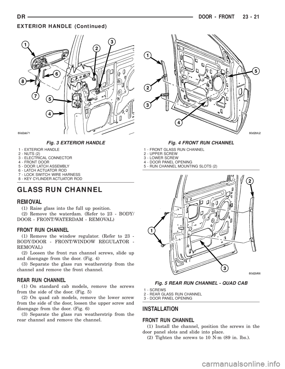
and disengage from the door. (Fig. 4)
(3) Separate the glass run weatherstrip from the
channel and remove the front channel.
REAR RUN CHANNEL
(1) On standard cab models, remove the screws
from the side of the door. (Fig. 5)
(2) On quad cab models, remove the lower screw
from the side of the door, loosen the upper screw and
disengage from the door. (Fig. 6)
(3) Separate the glass run weatherstrip from the
rear channel and remove the channel.
INSTALLATION
FRONT RUN CHANNEL
(1) Install the channel, position the screws in the
door panel slots and slide into place.
(2) Tighten the screws to 10 N´m (89 in. lbs.).
Fig. 3 EXTERIOR HANDLE
1 - EXTERIOR HANDLE
2 - NUTS (2)
3 - ELECTRICAL CONNECTOR
4 - FRONT DOOR
5 - DOOR LATCH ASSEMBLY
6 - LATCH ACTUATOR ROD
7 - LOCK SWITCH WIRE HARNESS
8 - KEY CYLINDER ACTUATOR ROD
Fig. 4 FRONT RUN CHANNEL
1 - FRONT GLASS RUN CHANNEL
2 - UPPER SCREW
3 - LOWER SCREW
4 - DOOR PANEL OPENING
5 - RUN CHANNEL MOUNTING SLOTS (2)
Fig. 5 REAR RUN CHANNEL - QUAD CAB
1 - SCREWS
2 - REAR GLASS RUN CHANNEL
3 - DOOR PANEL OPENING
DRDOOR - FRONT 23 - 21
EXTERIOR HANDLE (Continued)
Page 2600 of 2895
(4) Install the screws near the inside handle and
at the mirror flag.
(5) Install the interior handle. (Refer to 23 -
BODY/DOOR - FRONT/INSIDE HANDLE ACTUA-
TOR - INSTALLATION)
(6) Install the window crank, if equipped.
WATERDAM
REMOVAL
CAUTION: Do not allow the waterdam or adhesive
to become contaminated with dirt or other foreign
substances.
Do not damage the waterdam during removal and
installation.If the waterdam becomes contaminated or dam-
aged, replace the waterdam.
(1) Remove the inside handle actuator. (Refer to 23
- BODY/DOOR - FRONT/INSIDE HANDLE ACTUA-
TOR - REMOVAL)
(2) Remove the speaker. (Refer to 8 - ELECTRI-
CAL/AUDIO/SPEAKER - REMOVAL)
(3) Separate the waterdam from the inner door
panel and off of the latch linkages.
INSTALLATION
CAUTION: Do not allow the waterdam or adhesive
to become contaminated with dirt or other foreign
substances.
Do not damage the waterdam during removal and
installation.
If the waterdam becomes contaminated or dam-
aged, replace the waterdam.
(1) Position the wire harness and actuator rods
through the holes in the waterdam.
(2) Secure the waterdam to the inner door panel.
(3) Install the speaker. (Refer to 8 - ELECTRICAL/
AUDIO/SPEAKER - INSTALLATION)
(4) Install the inside handle actuator. (Refer to 23 -
BODY/DOOR - FRONT/INSIDE HANDLE ACTUA-
TOR - INSTALLATION)
WINDOW REGULATOR -
POWER
REMOVAL
(1) Remove the waterdam. (Refer to 23 - BODY/
DOOR - FRONT/WATERDAM - REMOVAL)
(2) Remove the window switch from the door trim
panel and reconnect it to the door harness.
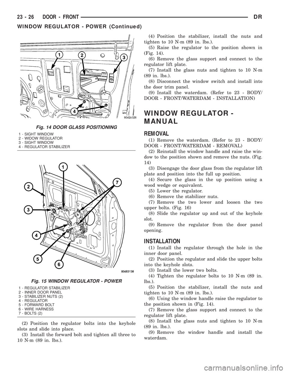
(3) Raise the window to the position shown and
remove the nuts. (Fig. 14)
(4) Disengage the door glass from the regulator lift
plate and position into the full up position.
(5) Secure the glass in the up position using a
wood wedge or equivalent.
(6) Lower the regulator.
(7) Remove the stabilizer nuts.
(8) Remove the forward regulator bolt and loosen
the other two. (Fig. 15)
(9) Slide the regulator up and out of the keyhole
slots in the door panel.
(10) Disconnect the electrical connector and
remove the regulator.
INSTALLATION
(1) Install the regulator through the door panel
opening and connect the electrical connector.
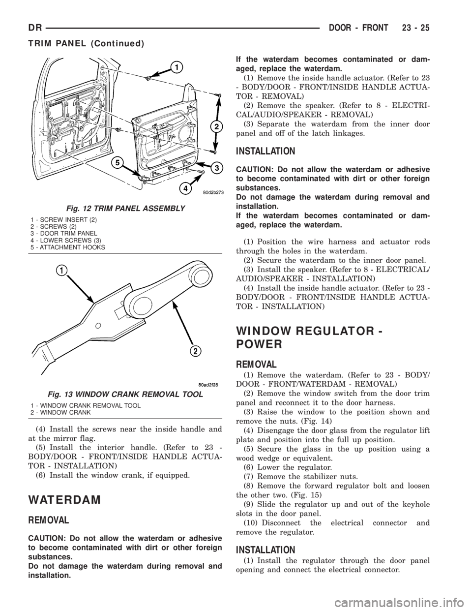
Fig. 12 TRIM PANEL ASSEMBLY
1 - SCREW INSERT (2)
2 - SCREWS (2)
3 - DOOR TRIM PANEL
4 - LOWER SCREWS (3)
5 - ATTACHMENT HOOKS
Fig. 13 WINDOW CRANK REMOVAL TOOL
1 - WINDOW CRANK REMOVAL TOOL
2 - WINDOW CRANK
DRDOOR - FRONT 23 - 25
TRIM PANEL (Continued)
Page 2601 of 2895
(2) Position the regulator bolts into the keyhole
slots and slide into place.
(3) Install the forward bolt and tighten all three to
10 N´m (89 in. lbs.).(4) Position the stabilizer, install the nuts and
tighten to 10 N´m (89 in. lbs.).
(5) Raise the regulator to the position shown in
(Fig. 14).
(6) Remove the glass support and connect to the
regulator lift plate.
(7) Install the glass nuts and tighten to 10 N´m
(89 in. lbs.).
(8) Disconnect the window switch and install into
the door trim panel.
(9) Install the waterdam. (Refer to 23 - BODY/
DOOR - FRONT/WATERDAM - INSTALLATION)
WINDOW REGULATOR -
MANUAL
REMOVAL
(1) Remove the waterdam. (Refer to 23 - BODY/
DOOR - FRONT/WATERDAM - REMOVAL)
(2) Reinstall the window handle and raise the win-
dow to the position shown and remove the nuts. (Fig.
14)
(3) Disengage the door glass from the regulator lift
plate and position into the full up position.
(4) Secure the glass in the up position using a
wood wedge or equivalent.
(5) Lower the regulator.
(6) Remove the stabilizer nuts.
(7) Remove the two lower and loosen the two
upper bolts. (Fig. 16)
(8) Slide the regulator up and out of the keyhole
slot.
(9) Remove the regulator from the door panel
opening.
INSTALLATION
(1) Install the regulator through the hole in the
inner door panel.
(2) Position the regulator and slide the upper bolts
into the keyhole slots.
(3) Install the lower two bolts.
(4) Tighten the regulator bolts to 10 N´m (89 in.
lbs.).
(5) Position the stabilizer, install the nuts and
tighten to 10 N´m (89 in. lbs.).
(6) Using the window handle raise the regulator to
the position shown in (Fig. 14).
(7) Remove the glass support and connect to the
regulator lift plate.
(8) Install the glass nuts and tighten to 10 N´m
(89 in. lbs.).
(9) Remove the window handle and install the
waterdam.
Fig. 14 DOOR GLASS POSITIONING
1 - SIGHT WINDOW
2 - WIDOW REGULATOR
3 - SIGHT WINDOW
4 - REGULATOR STABILIZER
Fig. 15 WINDOW REGULATOR - POWER
1 - REGULATOR STABILIZER
2 - INNER DOOR PANEL
3 - STABILIZER NUTS (2)
4 - REGULATOR
5 - FORWARD BOLT
6 - WIRE HARNESS
7 - BOLTS (2)
23 - 26 DOOR - FRONTDR
WINDOW REGULATOR - POWER (Continued)
Page 2605 of 2895
DOOR GLASS
REMOVAL
(1) Remove the glass run channels. (Refer to 23 -
BODY/DOORS - REAR/GLASS RUN CHANNEL -
REMOVAL)
(2) Remove the glass support and place the glass
into the bottom of the door.
(3) Separate the glass run weatherstrip from the
rear of the window opening.
(4) Remove the inner belt molding. (Refer to 23 -
BODY/WEATHERSTRIP/SEALS/FRONT DOOR
INNER BELT WEATHERSTRIP - REMOVAL)
(5) Remove the glass from the window opening.
INSTALLATION
(1) Install the glass through the window opening
and pace the glass into the bottom of the door.
(2) Install the inner belt molding. (Refer to 23 -
BODY/WEATHERSTRIP/SEALS/FRONT DOOR
INNER BELT WEATHERSTRIP - INSTALLATION)
(3) Stuff the glass run weatherstrip into the win-
dow frame.
(4) Secure the glass in the up position using a
wood wedge or equivalent.
(5) Install the glass run channels. (Refer to 23 -
BODY/DOORS - REAR/GLASS RUN CHANNEL -
INSTALLATION)
EXTERIOR HANDLE
REMOVAL
(1) Remove the front glass run channel. (Refer to
23 - BODY/DOORS - REAR/GLASS RUN CHANNEL
- REMOVAL)
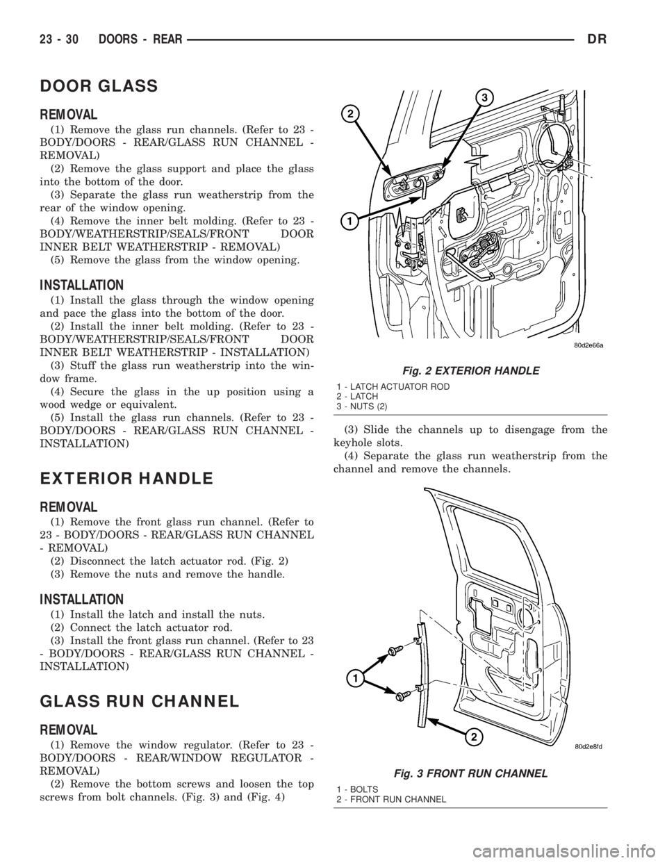
(2) Disconnect the latch actuator rod. (Fig. 2)
(3) Remove the nuts and remove the handle.
INSTALLATION
(1) Install the latch and install the nuts.
(2) Connect the latch actuator rod.
(3) Install the front glass run channel. (Refer to 23
- BODY/DOORS - REAR/GLASS RUN CHANNEL -
INSTALLATION)
GLASS RUN CHANNEL
REMOVAL
(1) Remove the window regulator. (Refer to 23 -
BODY/DOORS - REAR/WINDOW REGULATOR -
REMOVAL)
(2) Remove the bottom screws and loosen the top
screws from bolt channels. (Fig. 3) and (Fig. 4)(3) Slide the channels up to disengage from the
keyhole slots.
(4) Separate the glass run weatherstrip from the
channel and remove the channels.
Fig. 2 EXTERIOR HANDLE
1 - LATCH ACTUATOR ROD
2-LATCH
3 - NUTS (2)
Fig. 3 FRONT RUN CHANNEL
1 - BOLTS
2 - FRONT RUN CHANNEL
23 - 30 DOORS - REARDR
Page 2606 of 2895
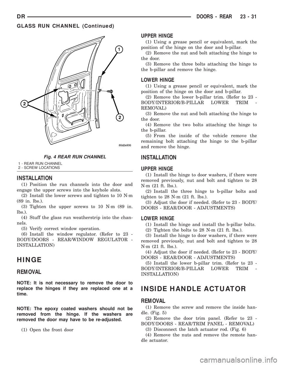
INSTALLATION
(1) Position the run channels into the door and
engage the upper screws into the keyhole slots.
(2) Install the lower screws and tighten to 10 N´m
(89 in. lbs.).
(3) Tighten the upper screws to 10 N´m (89 in.
lbs.).
(4) Stuff the glass run weatherstrip into the chan-
nels.
(5) Verify correct window operation.
(6) Install the window regulator. (Refer to 23 -
BODY/DOORS - REAR/WINDOW REGULATOR -
INSTALLATION)
HINGE
REMOVAL
NOTE: It is not necessary to remove the door to
replace the hinges if they are replaced one at a
time.
NOTE: The epoxy coated washers should not be
removed from the hinge. If the washers are
removed the door may have to be re-adjusted.
(1) Open the front door
UPPER HINGE
(1) Using a grease pencil or equivalent, mark the
position of the hinge on the door and b-pillar.
(2) Remove the nut and bolt attaching the hinge to
the door.
(3) Remove the three bolts attaching the hinge to
the b-pillar and remove the hinge.
LOWER HINGE
(1) Using a grease pencil or equivalent, mark the
position of the hinge on the door and b-pillar.
(2) Remove the lower b-pillar trim. (Refer to 23 -
BODY/INTERIOR/B-PILLAR LOWER TRIM -
REMOVAL)
(3) Remove the nut and bolt attaching the hinge to
the door.
(4) Remove the two bolts attaching the hinge to
the b-pillar.
(5) From the inside of the vehicle remove the
remaining bolt attaching the hinge to the b-pillar
and remove the hinge.
INSTALLATION
UPPER HINGE
(1) Install the hinge to door washers, if there were
removed previously, nut and bolt and tighten to 28
N´m (21 ft. lbs.).
(2) Install the three hinge to b-pillar bolts and
tighten to 28 N´m (21 ft. lbs.).
(3) Adjust the door if needed. (Refer to 23 - BODY/
DOORS - REAR/DOOR - ADJUSTMENTS)
LOWER HINGE
(1) Install the hinge and install the b-pillar bolts.
(2) Tighten the bolts to 28 N´m (21 ft. lbs.).
(3) Install the hinge to door washers, if there were
removed previously, nut and bolt and tighten to 28
N´m (21 ft. lbs.).
(4) Adjust the door if needed. (Refer to 23 - BODY/
DOORS - REAR/DOOR - ADJUSTMENTS)
(5) Install the lower b-pillar trim. (Refer to 23 -
BODY/INTERIOR/B-PILLAR LOWER TRIM -
INSTALLATION)
INSIDE HANDLE ACTUATOR
REMOVAL
(1) Remove the screw and remove the inside han-
dle. (Fig. 5)
(2) Remove the door trim panel. (Refer to 23 -
BODY/DOORS - REAR/TRIM PANEL - REMOVAL)
(3) Disconnect the latch actuator rod. (Fig. 6)
(4) Remove the nuts and remove the remote han-
dle actuator.
Fig. 4 REAR RUN CHANNEL
1 - REAR RUN CHANNEL
2 - SCREW LOCATIONS
DRDOORS - REAR 23 - 31
GLASS RUN CHANNEL (Continued)
Page 2609 of 2895
WATERDAM
REMOVAL
(1) Remove the inside handle actuator. (Refer to 23
- BODY/DOORS - REAR/INSIDE HANDLE ACTUA-
TOR - REMOVAL)
(2) Remove the speaker. (Refer to 8 - ELECTRI-
CAL/AUDIO/SPEAKER - REMOVAL)
(3) Separate the waterdam from the inner door
panel and off of the latch linkages.
INSTALLATION
(1) Position the wire harness and actuator rods
through the holes in the waterdam.
(2) Secure the waterdam to the inner door panel.
(3) Install the speaker. (Refer to 8 - ELECTRICAL/
AUDIO/SPEAKER - INSTALLATION)
(4) Install the inside handle actuator. (Refer to 23 -
BODY/DOORS - REAR/INSIDE HANDLE ACTUA-
TOR - INSTALLATION)
WINDOW REGULATOR -
POWER
REMOVAL
(1) Remove the waterdam. (Refer to 23 - BODY/
DOORS - REAR/WATERDAM - REMOVAL)
(2) Remove the window switch from the door trim
panel and reconnect it to the door wire harness.
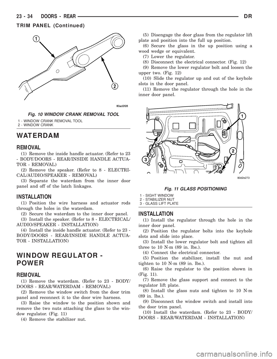
(3) Raise the window to the position shown and
remove the two nuts attaching the glass to the win-
dow regulator. (Fig. 11)
(4) Remove the stabilizer nut.(5) Disengage the door glass from the regulator lift
plate and position into the full up position.
(6) Secure the glass in the up position using a
wood wedge or equivalent.
(7) Lower the regulator.
(8) Disconnect the electrical connector. (Fig. 12)
(9) Remove the lower regulator bolt and loosen the
upper two. (Fig. 12)
(10) Slide the regulator up and out of the keyhole
slots in the door panel.
(11) Remove the regulator through the hole in the
inner door panel.
INSTALLATION
(1) Install the regulator through the hole in the
inner door panel.
(2) Position the regulator bolts into the keyhole
slots and slide into place.
(3) Install the lower regulator bolt and tighten all
three to 10 N´m (89 in. lbs.).
(4) Connect the electrical connector.
(5) Position the stabilizer, install the nut and
tighten to 10 N´m (89 in. lbs.).
(6) Raise the regulator to the position shown in
(Fig. 11).
(7) Remove the glass support and connect to the
regulator lift plate.
(8) Install the glass nuts and tighten to 10 N´m
(89 in. lbs.).
(9) Disconnect the window switch and install into
the door trim panel.
(10) Install the waterdam. (Refer to 23 - BODY/
DOORS - REAR/WATERDAM - INSTALLATION)
Fig. 10 WINDOW CRANK REMOVAL TOOL
1 - WINDOW CRANK REMOVAL TOOL
2 - WINDOW CRANK
Fig. 11 GLASS POSITIONING
1 - SIGHT WINDOW
2 - STABILIZER NUT
3 - GLASS LIFT PLATE
23 - 34 DOORS - REARDR
TRIM PANEL (Continued)
Page 2610 of 2895
WINDOW REGULATOR -
MANUAL
REMOVAL
(1) Remove the waterdam. (Refer to 23 - BODY/
DOORS - REAR/WATERDAM - REMOVAL)
(2) Reinstall the window handle and raise the win-
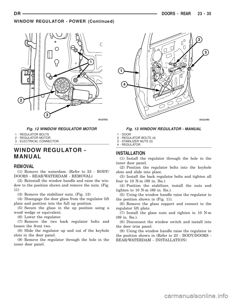
dow to the position shown and remove the nuts. (Fig.
11 )
(3) Remove the stabilizer nuts. (Fig. 13)
(4) Disengage the door glass from the regulator lift
plate and position into the full up position.
(5) Secure the glass in the up position using a
wood wedge or equivalent.
(6) Lower the regulator.
(7) Remove the two back regulator bolts and
loosen the front two.
(8) Slide the regulator up and out of the keyhole
slots in the door panel.
(9) Remove the regulator through the hole in the
inner door panel.
INSTALLATION
(1) Install the regulator through the hole in the
inner door panel.
(2) Position the regulator bolts into the keyhole
slots and slide into place.
(3) Install the back regulator bolts and tighten all
four to 10 N´m (89 in. lbs.).
(4) Position the stabilizer, install the nuts and
tighten to 10 N´m (89 in. lbs.).
(5) Using the window handle raise the regulator to
the position shown in (Fig. 11).
(6) Remove the glass support and connect to the
regulator lift plate.
(7) Install the glass nuts and tighten to 10 N´m
(89 in. lbs.).
(8) Disconnect the window switch and install into
the door trim panel.
(9) Using the window handle raise the regulator to
the position shown in (Refer to 23 - BODY/DOORS -
REAR/WATERDAM - INSTALLATION)
Fig. 12 WINDOW REGULATOR MOTOR
1 - REGULATOR BOLTS
2 - REGULATOR MOTOR
3 - ELECTRICAL CONNECTOR.
Fig. 13 WINDOW REGULATOR - MANUAL
1 - DOOR
2 - REGULATOR BOLTS (4)
3 - STABILIZER NUTS (2)
4 - REGULATOR
DRDOORS - REAR 23 - 35
WINDOW REGULATOR - POWER (Continued)
Page 2671 of 2895
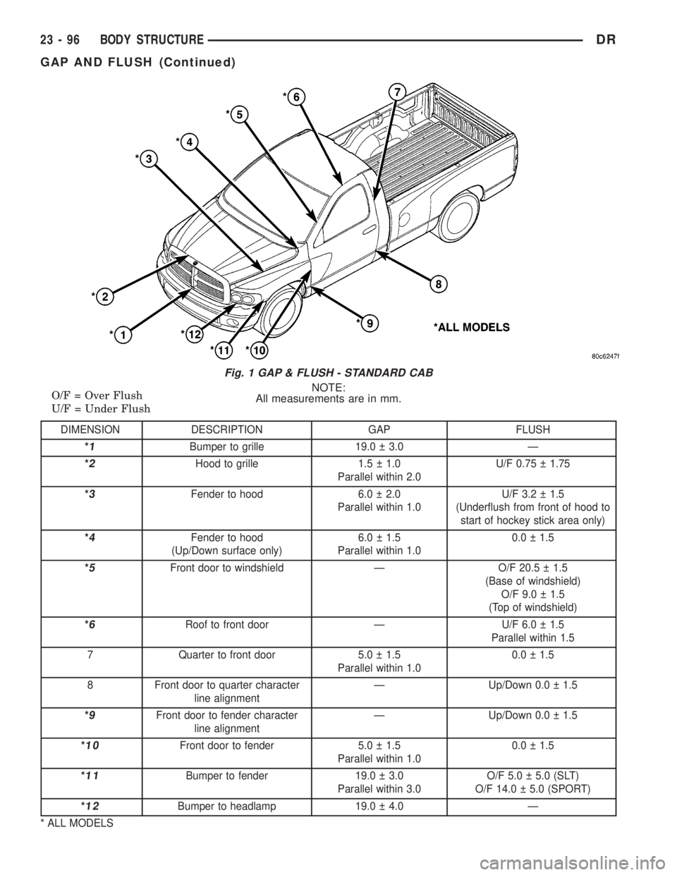
NOTE:
All measurements are in mm. O/F = Over Flush
U/F = Under Flush
DIMENSION DESCRIPTION GAP FLUSH
*
1Bumper to grille 19.0 3.0 Ð
*
2Hood to grille 1.5 1.0
Parallel within 2.0U/F 0.75 1.75
*
3Fender to hood 6.0 2.0
Parallel within 1.0U/F 3.2 1.5
(Underflush from front of hood to
start of hockey stick area only)
*
4Fender to hood
(Up/Down surface only)6.0 1.5
Parallel within 1.00.0 1.5
*
5Front door to windshield Ð O/F 20.5 1.5
(Base of windshield)
O/F 9.0 1.5
(Top of windshield)
*
6Roof to front door Ð U/F 6.0 1.5
Parallel within 1.5
7 Quarter to front door 5.0 1.5
Parallel within 1.00.0 1.5
8 Front door to quarter character
line alignmentÐ Up/Down 0.0 1.5
*
9Front door to fender character
line alignmentÐ Up/Down 0.0 1.5
*
10Front door to fender 5.0 1.5
Parallel within 1.00.0 1.5
*
11Bumper to fender 19.0 3.0
Parallel within 3.0O/F 5.0 5.0 (SLT)
O/F 14.0 5.0 (SPORT)
*
12Bumper to headlamp 19.0 4.0 Ð
* ALL MODELS
Fig. 1 GAP & FLUSH - STANDARD CAB
23 - 96 BODY STRUCTUREDR
GAP AND FLUSH (Continued)