2003 DODGE RAM key
[x] Cancel search: keyPage 2236 of 2895
OVERDRIVE SWITCH
DESCRIPTION
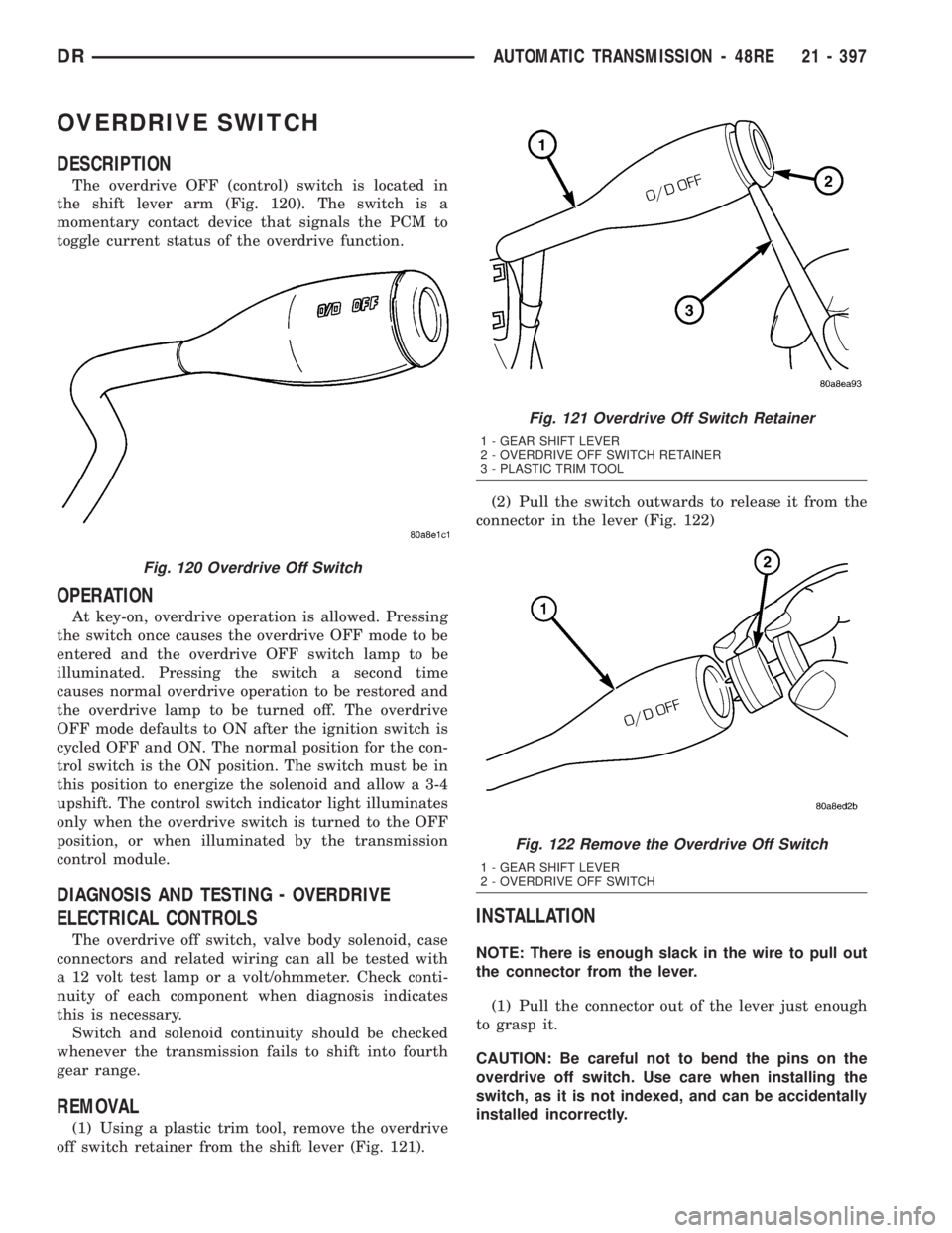
The overdrive OFF (control) switch is located in
the shift lever arm (Fig. 120). The switch is a
momentary contact device that signals the PCM to
toggle current status of the overdrive function.
OPERATION
At key-on, overdrive operation is allowed. Pressing
the switch once causes the overdrive OFF mode to be
entered and the overdrive OFF switch lamp to be
illuminated. Pressing the switch a second time
causes normal overdrive operation to be restored and
the overdrive lamp to be turned off. The overdrive
OFF mode defaults to ON after the ignition switch is
cycled OFF and ON. The normal position for the con-
trol switch is the ON position. The switch must be in
this position to energize the solenoid and allow a 3-4
upshift. The control switch indicator light illuminates
only when the overdrive switch is turned to the OFF
position, or when illuminated by the transmission
control module.
DIAGNOSIS AND TESTING - OVERDRIVE
ELECTRICAL CONTROLS
The overdrive off switch, valve body solenoid, case
connectors and related wiring can all be tested with
a 12 volt test lamp or a volt/ohmmeter. Check conti-
nuity of each component when diagnosis indicates
this is necessary.
Switch and solenoid continuity should be checked
whenever the transmission fails to shift into fourth
gear range.
REMOVAL
(1) Using a plastic trim tool, remove the overdrive
off switch retainer from the shift lever (Fig. 121).(2) Pull the switch outwards to release it from the
connector in the lever (Fig. 122)
INSTALLATION
NOTE: There is enough slack in the wire to pull out
the connector from the lever.
(1) Pull the connector out of the lever just enough
to grasp it.
CAUTION: Be careful not to bend the pins on the
overdrive off switch. Use care when installing the
switch, as it is not indexed, and can be accidentally
installed incorrectly.
Fig. 120 Overdrive Off Switch
Fig. 121 Overdrive Off Switch Retainer
1 - GEAR SHIFT LEVER
2 - OVERDRIVE OFF SWITCH RETAINER
3 - PLASTIC TRIM TOOL
Fig. 122 Remove the Overdrive Off Switch
1 - GEAR SHIFT LEVER
2 - OVERDRIVE OFF SWITCH
DRAUTOMATIC TRANSMISSION - 48RE 21 - 397
Page 2271 of 2895
THROTTLE VALVE CABLE
DESCRIPTION
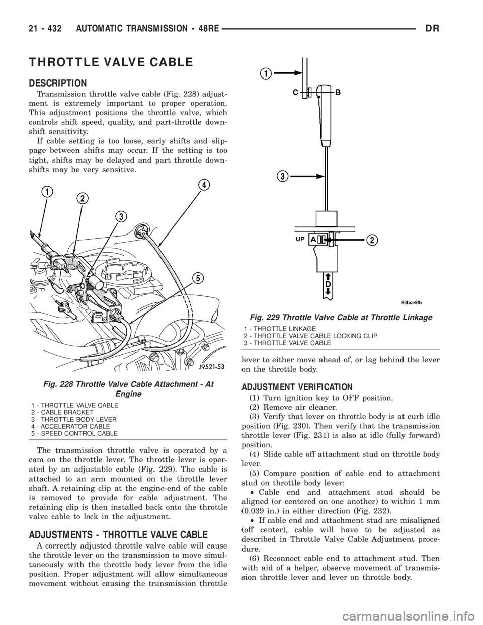
Transmission throttle valve cable (Fig. 228) adjust-
ment is extremely important to proper operation.
This adjustment positions the throttle valve, which
controls shift speed, quality, and part-throttle down-
shift sensitivity.
If cable setting is too loose, early shifts and slip-
page between shifts may occur. If the setting is too
tight, shifts may be delayed and part throttle down-
shifts may be very sensitive.
The transmission throttle valve is operated by a
cam on the throttle lever. The throttle lever is oper-
ated by an adjustable cable (Fig. 229). The cable is
attached to an arm mounted on the throttle lever
shaft. A retaining clip at the engine-end of the cable
is removed to provide for cable adjustment. The
retaining clip is then installed back onto the throttle
valve cable to lock in the adjustment.
ADJUSTMENTS - THROTTLE VALVE CABLE
A correctly adjusted throttle valve cable will cause
the throttle lever on the transmission to move simul-
taneously with the throttle body lever from the idle
position. Proper adjustment will allow simultaneous
movement without causing the transmission throttlelever to either move ahead of, or lag behind the lever
on the throttle body.
ADJUSTMENT VERIFICATION
(1) Turn ignition key to OFF position.
(2) Remove air cleaner.
(3) Verify that lever on throttle body is at curb idle
position (Fig. 230). Then verify that the transmission
throttle lever (Fig. 231) is also at idle (fully forward)
position.
(4) Slide cable off attachment stud on throttle body
lever.
(5) Compare position of cable end to attachment
stud on throttle body lever:
²Cable end and attachment stud should be
aligned (or centered on one another) to within 1 mm
(0.039 in.) in either direction (Fig. 232).
²If cable end and attachment stud are misaligned
(off center), cable will have to be adjusted as
described in Throttle Valve Cable Adjustment proce-
dure.
(6) Reconnect cable end to attachment stud. Then
with aid of a helper, observe movement of transmis-
sion throttle lever and lever on throttle body.
Fig. 228 Throttle Valve Cable Attachment - At
Engine
1 - THROTTLE VALVE CABLE
2 - CABLE BRACKET
3 - THROTTLE BODY LEVER
4 - ACCELERATOR CABLE
5 - SPEED CONTROL CABLE
Fig. 229 Throttle Valve Cable at Throttle Linkage
1 - THROTTLE LINKAGE
2 - THROTTLE VALVE CABLE LOCKING CLIP
3 - THROTTLE VALVE CABLE
21 - 432 AUTOMATIC TRANSMISSION - 48REDR
Page 2379 of 2895
BRAKE TRANSMISSION SHIFT
INTERLOCK SYSTEM
DESCRIPTION
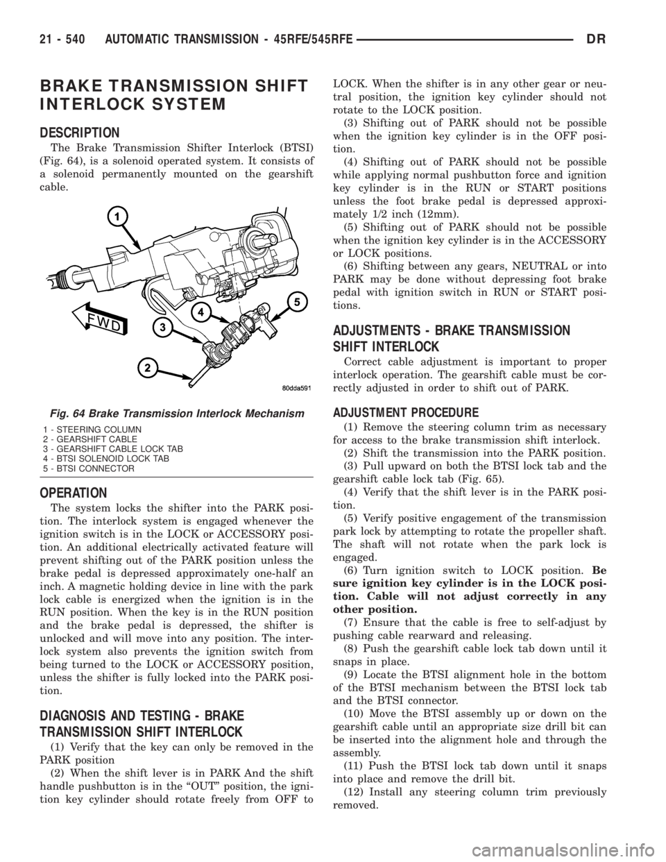
The Brake Transmission Shifter Interlock (BTSI)
(Fig. 64), is a solenoid operated system. It consists of
a solenoid permanently mounted on the gearshift
cable.
OPERATION
The system locks the shifter into the PARK posi-
tion. The interlock system is engaged whenever the
ignition switch is in the LOCK or ACCESSORY posi-
tion. An additional electrically activated feature will
prevent shifting out of the PARK position unless the
brake pedal is depressed approximately one-half an
inch. A magnetic holding device in line with the park
lock cable is energized when the ignition is in the
RUN position. When the key is in the RUN position
and the brake pedal is depressed, the shifter is
unlocked and will move into any position. The inter-
lock system also prevents the ignition switch from
being turned to the LOCK or ACCESSORY position,
unless the shifter is fully locked into the PARK posi-
tion.
DIAGNOSIS AND TESTING - BRAKE
TRANSMISSION SHIFT INTERLOCK
(1) Verify that the key can only be removed in the
PARK position
(2) When the shift lever is in PARK And the shift
handle pushbutton is in the ªOUTº position, the igni-
tion key cylinder should rotate freely from OFF toLOCK. When the shifter is in any other gear or neu-
tral position, the ignition key cylinder should not
rotate to the LOCK position.
(3) Shifting out of PARK should not be possible
when the ignition key cylinder is in the OFF posi-
tion.
(4) Shifting out of PARK should not be possible
while applying normal pushbutton force and ignition
key cylinder is in the RUN or START positions
unless the foot brake pedal is depressed approxi-
mately 1/2 inch (12mm).
(5) Shifting out of PARK should not be possible
when the ignition key cylinder is in the ACCESSORY
or LOCK positions.
(6) Shifting between any gears, NEUTRAL or into
PARK may be done without depressing foot brake
pedal with ignition switch in RUN or START posi-
tions.
ADJUSTMENTS - BRAKE TRANSMISSION
SHIFT INTERLOCK
Correct cable adjustment is important to proper
interlock operation. The gearshift cable must be cor-
rectly adjusted in order to shift out of PARK.
ADJUSTMENT PROCEDURE
(1) Remove the steering column trim as necessary
for access to the brake transmission shift interlock.
(2) Shift the transmission into the PARK position.
(3) Pull upward on both the BTSI lock tab and the
gearshift cable lock tab (Fig. 65).
(4) Verify that the shift lever is in the PARK posi-
tion.
(5) Verify positive engagement of the transmission
park lock by attempting to rotate the propeller shaft.
The shaft will not rotate when the park lock is
engaged.
(6) Turn ignition switch to LOCK position.Be
sure ignition key cylinder is in the LOCK posi-
tion. Cable will not adjust correctly in any
other position.
(7) Ensure that the cable is free to self-adjust by
pushing cable rearward and releasing.
(8) Push the gearshift cable lock tab down until it
snaps in place.
(9) Locate the BTSI alignment hole in the bottom
of the BTSI mechanism between the BTSI lock tab
and the BTSI connector.
(10) Move the BTSI assembly up or down on the
gearshift cable until an appropriate size drill bit can
be inserted into the alignment hole and through the
assembly.
(11) Push the BTSI lock tab down until it snaps
into place and remove the drill bit.
(12) Install any steering column trim previously
removed.
Fig. 64 Brake Transmission Interlock Mechanism
1 - STEERING COLUMN
2 - GEARSHIFT CABLE
3 - GEARSHIFT CABLE LOCK TAB
4 - BTSI SOLENOID LOCK TAB
5 - BTSI CONNECTOR
21 - 540 AUTOMATIC TRANSMISSION - 45RFE/545RFEDR
Page 2380 of 2895
BTSI FUNCTION CHECK
(1) Verify removal of ignition key allowed in PARK
position only.
(2) When the shift lever is in PARK, the ignition
key cylinder should rotate freely from off to lock.
When the shifter is in any other position, the ignition
key should not rotate from off to lock.
(3) Shifting out of PARK should be possible when
the ignition key cylinder is in the off position.
(4) Shifting out of PARK should not be possible
while applying normal force, and ignition key cylin-
der is in the run or start positions, unless the foot
brake pedal is depressed approximately 1/2 inch
(12mm).
(5) Shifting out of PARK should not be possible
when the ignition key cylinder is in the accessory or
lock position.
(6) Shifting between any gear and NEUTRAL, or
PARK, may be done without depressing foot brake
with ignition switch in run or start positions.
(7) Engine starts must be possible with shifter
lever in PARK or NEUTRAL positions only. Engine
starts must not be possible in any position other than
PARK or NEUTRAL.
(8) With shifter lever in the:
²PARK position - Apply upward force on the shift
arm and remove pressure. Engine starts must be
possible.
²PARK position - Apply downward force on the
shift arm and remove pressure. Engine starts must
be possible.
²NEUTRAL position - Normal position. Engine
starts must be possible.²NEUTRAL position - Engine running and brakes
applied, apply upward force on the shift arm. Trans-
mission shall not be able to shift from neutral to
reverse.
FLUID AND FILTER
DIAGNOSIS AND TESTING
DIAGNOSIS AND TESTING - EFFECTS OF
INCORRECT FLUID LEVEL
A low fluid level allows the pump to take in air
along with the fluid. Air in the fluid will cause fluid
pressures to be low and develop slower than normal.
If the transmission is overfilled, the gears churn the
fluid into foam. This aerates the fluid and causing
the same conditions occurring with a low level. In
either case, air bubbles cause fluid overheating, oxi-
dation and varnish buildup which interferes with
valve and clutch operation. Foaming also causes fluid
expansion which can result in fluid overflow from the
transmission vent or fill tube. Fluid overflow can eas-
ily be mistaken for a leak if inspection is not careful.
DIAGNOSIS AND TESTING - CAUSES OF
BURNT FLUID
Burnt, discolored fluid is a result of overheating
which has three primary causes.
(1) Internal clutch slippage, usually caused by low
line pressure, inadequate clutch apply pressure, or
clutch seal failure.
(2) A result of restricted fluid flow through the
main and/or auxiliary cooler. This condition is usu-
ally the result of a faulty or improperly installed
drainback valve, a damaged main cooler, or severe
restrictions in the coolers and lines caused by debris
or kinked lines.
(3) Heavy duty operation with a vehicle not prop-
erly equipped for this type of operation. Trailer tow-
ing or similar high load operation will overheat the
transmission fluid if the vehicle is improperly
equipped. Such vehicles should have an auxiliary
transmission fluid cooler, a heavy duty cooling sys-
tem, and the engine/axle ratio combination needed to
handle heavy loads.
DIAGNOSIS AND TESTING - FLUID
CONTAMINATION
Transmission fluid contamination is generally a
result of:
²adding incorrect fluid
²failure to clean dipstick and fill tube when
checking level
²engine coolant entering the fluid
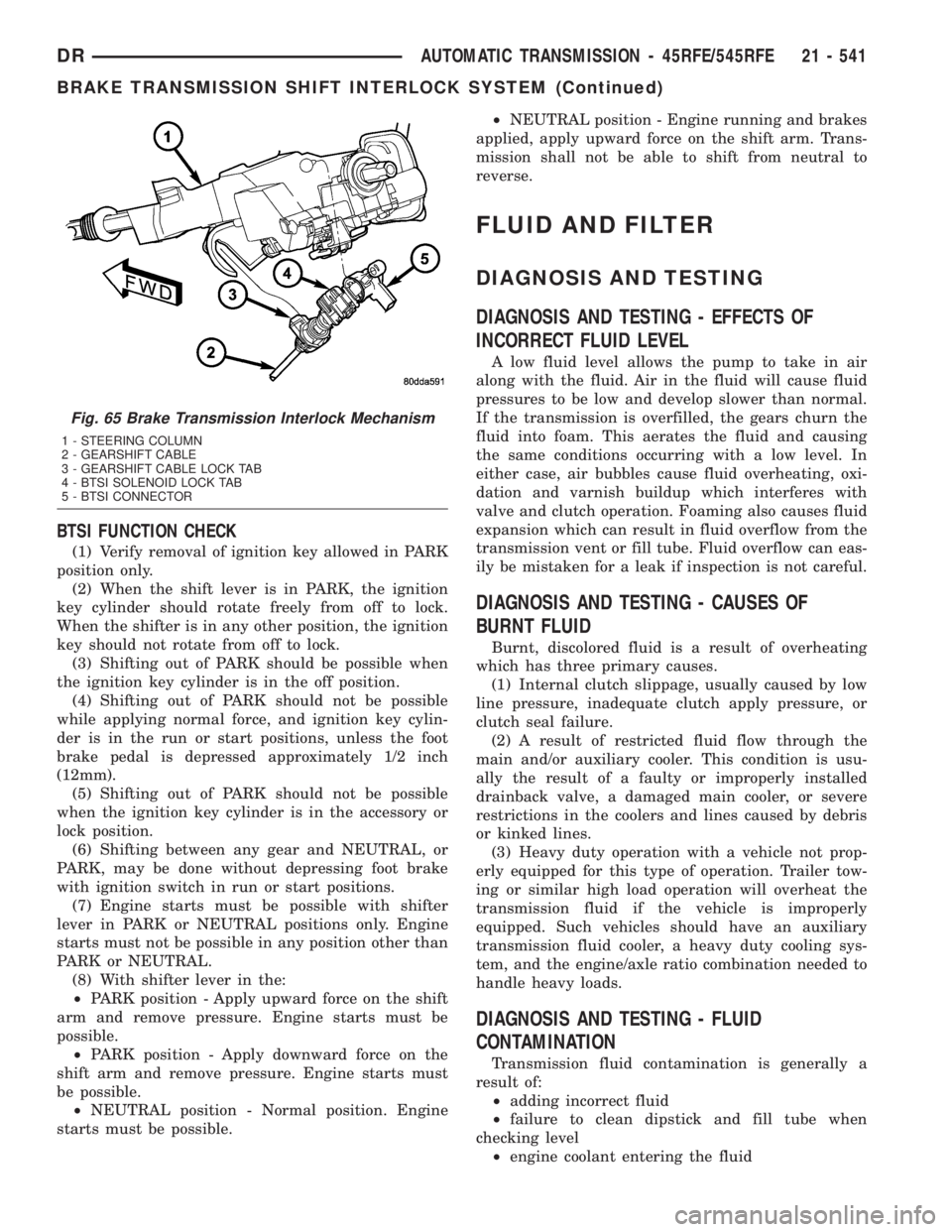
Fig. 65 Brake Transmission Interlock Mechanism
1 - STEERING COLUMN
2 - GEARSHIFT CABLE
3 - GEARSHIFT CABLE LOCK TAB
4 - BTSI SOLENOID LOCK TAB
5 - BTSI CONNECTOR
DRAUTOMATIC TRANSMISSION - 45RFE/545RFE 21 - 541
BRAKE TRANSMISSION SHIFT INTERLOCK SYSTEM (Continued)
Page 2407 of 2895
OVERDRIVE SWITCH
DESCRIPTION
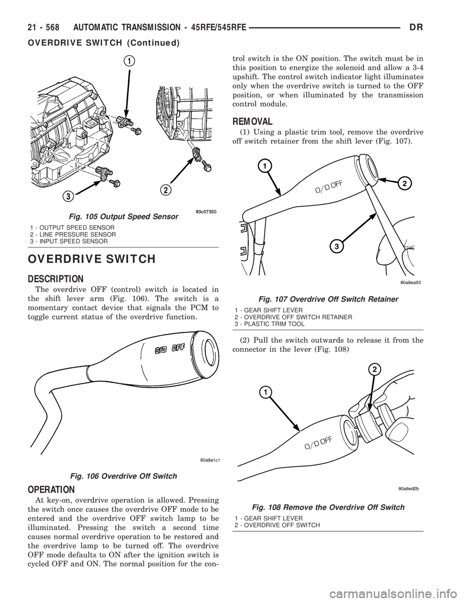
The overdrive OFF (control) switch is located in
the shift lever arm (Fig. 106). The switch is a
momentary contact device that signals the PCM to
toggle current status of the overdrive function.
OPERATION
At key-on, overdrive operation is allowed. Pressing
the switch once causes the overdrive OFF mode to be
entered and the overdrive OFF switch lamp to be
illuminated. Pressing the switch a second time
causes normal overdrive operation to be restored and
the overdrive lamp to be turned off. The overdrive
OFF mode defaults to ON after the ignition switch is
cycled OFF and ON. The normal position for the con-trol switch is the ON position. The switch must be in
this position to energize the solenoid and allow a 3-4
upshift. The control switch indicator light illuminates
only when the overdrive switch is turned to the OFF
position, or when illuminated by the transmission
control module.
REMOVAL
(1) Using a plastic trim tool, remove the overdrive
off switch retainer from the shift lever (Fig. 107).
(2) Pull the switch outwards to release it from the
connector in the lever (Fig. 108)
Fig. 105 Output Speed Sensor
1 - OUTPUT SPEED SENSOR
2 - LINE PRESSURE SENSOR
3 - INPUT SPEED SENSOR
Fig. 106 Overdrive Off Switch
Fig. 107 Overdrive Off Switch Retainer
1 - GEAR SHIFT LEVER
2 - OVERDRIVE OFF SWITCH RETAINER
3 - PLASTIC TRIM TOOL
Fig. 108 Remove the Overdrive Off Switch
1 - GEAR SHIFT LEVER
2 - OVERDRIVE OFF SWITCH
21 - 568 AUTOMATIC TRANSMISSION - 45RFE/545RFEDR
OVERDRIVE SWITCH (Continued)
Page 2413 of 2895
(5) Install the number 9 bearing onto the front of
the reverse planetary carrier with the outer race
toward the carrier and the inner race facing upward
(Fig. 116).
(6) Install the reverse planetary gear carrier into
the input carrier (Fig. 116).
(7) Install the input annulus gear into the input
carrier (Fig. 116).
(8) Install the snap-ring to hold the input annulus
gear into the input carrier (Fig. 116).
SHIFT MECHANISM
DESCRIPTION
The gear shift mechanism provides six shift posi-
tions which are:
²Park (P)
²Reverse (R)
²Neutral (N)
²Drive (D)
²Manual second (2)
²Manual low (1)
OPERATION
MANUAL LOW (1) range provides first gear only.
Overrun braking is also provided in this range.
MANUAL SECOND (2) range provides first and sec-
ond gear only.
DRIVE range provides FIRST, SECOND, THIRD,
OVERDRIVE FOURTH, and OVERDRIVE FIFTH (if
applicable) gear ranges. The shift into OVERDRIVE
FOURTH and FIFTH (if applicable) gear ranges
occurs only after the transmission has completed the
shift into D THIRD gear range. No further movement
of the shift mechanism is required to complete the
3-4 or 4-5 (if applicable) shifts.
The FOURTH and FIFTH (if applicable) gear
upshifts occur automatically when the overdrive
selector switch is in the ON position. No upshift to
FOURTH or FIFTH (if applicable) gears will occur if
any of the following are true:
²The transmission fluid temperature is below 10É
C (50É F) or above 121É C (250É F).
²The shift to THIRD is not yet complete.
²Vehicle speed is too low for the 3-4 or 4-5 (if
applicable) shifts to occur.
Upshifts into FOURTH or FIFTH (if applicable)
will be delayed when the transmission fluid temper-
ature is below 4.5É C (40É F) or above 115.5É C (240É
F).
SOLENOID SWITCH VALVE
DESCRIPTION
The Solenoid Switch Valve (SSV) is located in the
valve body and controls the direction of the transmis-
sion fluid when the L/R-TCC solenoid is energized.
OPERATION
The Solenoid Switch Valve controls line pressure
from the LR-TCC solenoid. In 1st gear, the SSV will
be in the downshifted position, thus directing fluid to
the L/R clutch circuit. In 2nd, 3rd, 4th, and 5th (if
applicable) gears, the solenoid switch valve will be in
the upshifted position and directs the fluid into the
torque converter clutch (TCC) circuit.
When shifting into 1st gear, a special hydraulic
sequence is performed to ensure SSV movement into
the downshifted position. The L/R pressure switch is
monitored to confirm SSV movement. If the move-
ment is not confirmed (the L/R pressure switch does
not close), 2nd gear is substituted for 1st. A DTC will
be set after three unsuccessful attempts are made to
get into 1st gear in one given key start.
SOLENOIDS
DESCRIPTION
The typical electrical solenoid used in automotive
applications is a linear actuator. It is a device that
produces motion in a straight line. This straight line
motion can be either forward or backward in direc-
tion, and short or long distance.
A solenoid is an electromechanical device that uses
a magnetic force to perform work. It consists of a coil
of wire, wrapped around a magnetic core made from
steel or iron, and a spring loaded, movable plunger,
which performs the work, or straight line motion.
The solenoids used in transmission applications
are attached to valves which can be classified asnor-
mally openornormally closed. Thenormally
opensolenoid valve is defined as a valve which
allows hydraulic flow when no current or voltage is
applied to the solenoid. Thenormally closedsole-
noid valve is defined as a valve which does not allow
hydraulic flow when no current or voltage is applied
to the solenoid. These valves perform hydraulic con-
trol functions for the transmission and must there-
fore be durable and tolerant of dirt particles. For
these reasons, the valves have hardened steel pop-
pets and ball valves. The solenoids operate the valves
directly, which means that the solenoids must have
very high outputs to close the valves against the siz-
able flow areas and line pressures found in current
transmissions. Fast response time is also necessary
to ensure accurate control of the transmission.
21 - 574 AUTOMATIC TRANSMISSION - 45RFE/545RFEDR
PLANETARY GEARTRAIN (Continued)
Page 2424 of 2895
OPERATION
NOTE: Refer to the Hydraulic Schematics for a
visual aid in determining valve location, operation
and design.
SOLENOID SWITCH VALVE
The Solenoid Switch Valve (SSV) controls the direc-
tion of the transmission fluid when the L/R-TCC sole-
noid is energized.
When shifting into 1st gear, a special hydraulic
sequence is performed to ensure SSV movement into
the downshifted position. The L/R pressure switch is
monitored to confirm SSV movement. If the move-
ment is not confirmed (the L/R pressure switch does
not close), 2nd gear is substituted for 1st. A DTC will
be set after three unsuccessful attempts are made to
get into 1st gear in one given key start.
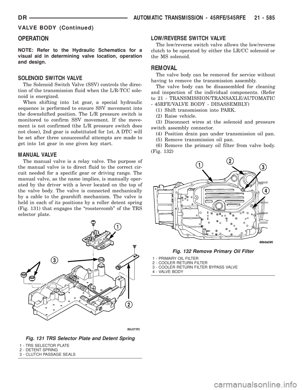
MANUAL VALVE
The manual valve is a relay valve. The purpose of
the manual valve is to direct fluid to the correct cir-
cuit needed for a specific gear or driving range. The
manual valve, as the name implies, is manually oper-
ated by the driver with a lever located on the top of
the valve body. The valve is connected mechanically
by a cable to the gearshift mechanism. The valve is
held in each of its positions by a roller detent spring
(Fig. 131) that engages the ªroostercombº of the TRS
selector plate.
LOW/REVERSE SWITCH VALVE
The low/reverse switch valve allows the low/reverse
clutch to be operated by either the LR/CC solenoid or
the MS solenoid.
REMOVAL
The valve body can be removed for service without
having to remove the transmission assembly.
The valve body can be disassembled for cleaning
and inspection of the individual components. (Refer
to 21 - TRANSMISSION/TRANSAXLE/AUTOMATIC
- 45RFE/VALVE BODY - DISASSEMBLY)
(1) Shift transmission into PARK.
(2) Raise vehicle.
(3) Disconnect wires at the solenoid and pressure
switch assembly connector.
(4) Position drain pan under transmission oil pan.
(5) Remove transmission oil pan.
(6) Remove the primary oil filter from valve body.
(Fig. 132)
Fig. 131 TRS Selector Plate and Detent Spring
1 - TRS SELECTOR PLATE
2 - DETENT SPRING
3 - CLUTCH PASSAGE SEALS
Fig. 132 Remove Primary Oil Filter
1 - PRIMARY OIL FILTER
2 - COOLER RETURN FILTER
3 - COOLER RETURN FILTER BYPASS VALVE
4 - VALVE BODY
DRAUTOMATIC TRANSMISSION - 45RFE/545RFE 21 - 585
VALVE BODY (Continued)
Page 2578 of 2895
ROAD TESTING WIND NOISE
(1) Drive the vehicle to verify the general location
of the wind noise.
(2) Apply 50 mm (2 in.) masking tape in 150 mm
(6 in.) lengths along weatherstrips, weld seams or
moldings. After each length is applied, drive the vehi-
cle. If noise goes away after a piece of tape is applied,
remove tape, locate, and repair defect.
POSSIBLE CAUSE OF WIND NOISE
²Moldings standing away from body surface can
catch wind and whistle.
²Gaps in sealed areas behind overhanging body
flanges can cause wind-rushing sounds.
²Misaligned movable components.
²Missing or improperly installed plugs in pillars.
²Weld burn through holes.
STANDARD PROCEDURE
STANDARD PROCEDURE - BODY LUBRICATION
All mechanisms and linkages should be lubricated
when necessary. This will maintain ease of operation
and provide protection against rust and excessive
wear. The weatherstrip seals should be lubricated to
prolong their life as well as to improve door sealing.
All applicable exterior and interior vehicle operat-
ing mechanisms should be inspected and cleaned.
Pivot/sliding contact areas on the mechanisms should
then be lubricated.
(1) When necessary, lubricate the operating mech-
anisms with the specified lubricants.
(2) Apply silicone lubricant to a cloth and wipe it
on door seals to avoid over-spray that can soil pas-
senger's clothing.
(3) Before applying lubricant, the component
should be wiped clean. After lubrication, any excess
lubricant should be removed.
(4) The hood latch, latch release mechanism, latch
striker, and safety latch should be lubricated period-
ically.
(5) The door lock cylinders should be lubricated
twice each year (preferably autumn and spring).
²Spray a small amount of lock cylinder lubricant
directly into the lock cylinder.
²Apply a small amount to the key and insert it
into the lock cylinder.
²Rotate it to the locked position and then back to
the unlocked position several times.
²Remove the key. Wipe the lubricant from it with
a clean cloth to avoid soiling of clothing.
STANDARD PROCEDURE - HEAT STAKING
(1) Remove trim panel.(2) Bend or move the trim panel components at
the heat staked joints. Observe the heat staked loca-
tions and/or component seams for looseness.
(3) Heat stake the components.
(a) If the heat staked or component seam loca-
tion is loose, hold the two components tightly
together and using a soldering gun with a flat tip,
melt the material securing the components
together. Do not over heat the affected area, dam-
age to the exterior of the trim panel may occur.
(b) If the heat staked material is broken or miss-
ing, use a hot glue gun to apply new material to
the area to be repaired. The panels that are being
heat staked must be held together while the apply-
ing the glue. Once the new material is in place, it
may be necessary to use a soldering gun to melt
the newly applied material. Do not over heat the
affected area, damage to the exterior of the trim
panel may occur.
(4) Allow the repaired area to cool and verify the
repair.
(5) Install trim panel.
STANDARD PROCEDURE - PLASTIC BODY
PANEL REPAIR
There are many different types of plastics used in
today's automotive environment. We group plastics in
three different categories: Rigid, Semi-Rigid, and
Flexible. Any of these plastics may require the use of
an adhesion promoter for repair. These types of plas-
tic are used extensively on DaimlerChrysler Motors
vehicles. Always follow repair material manufactur-
er's plastic identification and repair procedures.
Rigid Plastics:
Examples of rigid plastic use: Fascias, Hoods,
Doors, and other Body Panels, which include SMC,
ABS, and Polycarbonates.
Semi-Rigid Plastics:
Examples of semi-rigid plastic use: Interior Panels,
Under Hood Panels, and other Body Trim Panels.
Flexible Plastics:
Examples of flexible plastic use: Fascias, Body
Moldings, and upper and lower Fascia Covers.
Repair Procedure:
The repair procedure for all three categories of
plastics is basically the same. The one difference is
the material used for the repair. The materials must
be specific for each substrate, rigid repair material
for rigid plastic repair, semi-rigid repair material for
semi-rigid plastic repair and flexible repair material
for flexible plastic repair.
DRBODY 23 - 3
BODY (Continued)