2003 DODGE RAM key
[x] Cancel search: keyPage 1804 of 2895
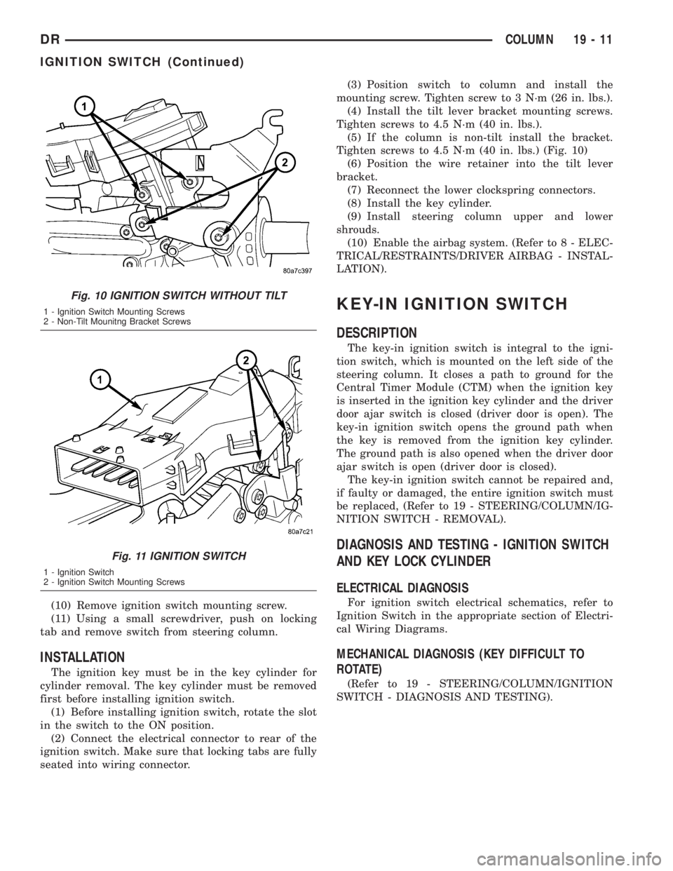
(10) Remove ignition switch mounting screw.
(11) Using a small screwdriver, push on locking
tab and remove switch from steering column.
INSTALLATION
The ignition key must be in the key cylinder for
cylinder removal. The key cylinder must be removed
first before installing ignition switch.
(1) Before installing ignition switch, rotate the slot
in the switch to the ON position.
(2) Connect the electrical connector to rear of the
ignition switch. Make sure that locking tabs are fully
seated into wiring connector.(3) Position switch to column and install the
mounting screw. Tighten screw to 3 N´m (26 in. lbs.).
(4) Install the tilt lever bracket mounting screws.
Tighten screws to 4.5 N´m (40 in. lbs.).
(5) If the column is non-tilt install the bracket.
Tighten screws to 4.5 N´m (40 in. lbs.) (Fig. 10)
(6) Position the wire retainer into the tilt lever
bracket.
(7) Reconnect the lower clockspring connectors.
(8) Install the key cylinder.
(9) Install steering column upper and lower
shrouds.
(10) Enable the airbag system. (Refer to 8 - ELEC-
TRICAL/RESTRAINTS/DRIVER AIRBAG - INSTAL-
LATION).
KEY-IN IGNITION SWITCH
DESCRIPTION
The key-in ignition switch is integral to the igni-
tion switch, which is mounted on the left side of the
steering column. It closes a path to ground for the
Central Timer Module (CTM) when the ignition key
is inserted in the ignition key cylinder and the driver
door ajar switch is closed (driver door is open). The
key-in ignition switch opens the ground path when
the key is removed from the ignition key cylinder.
The ground path is also opened when the driver door
ajar switch is open (driver door is closed).
The key-in ignition switch cannot be repaired and,
if faulty or damaged, the entire ignition switch must
be replaced, (Refer to 19 - STEERING/COLUMN/IG-
NITION SWITCH - REMOVAL).
DIAGNOSIS AND TESTING - IGNITION SWITCH
AND KEY LOCK CYLINDER
ELECTRICAL DIAGNOSIS
For ignition switch electrical schematics, refer to
Ignition Switch in the appropriate section of Electri-
cal Wiring Diagrams.
MECHANICAL DIAGNOSIS (KEY DIFFICULT TO
ROTATE)
(Refer to 19 - STEERING/COLUMN/IGNITION
SWITCH - DIAGNOSIS AND TESTING).
Fig. 10 IGNITION SWITCH WITHOUT TILT
1 - Ignition Switch Mounting Screws
2 - Non-Tilt Mounitng Bracket Screws
Fig. 11 IGNITION SWITCH
1 - Ignition Switch
2 - Ignition Switch Mounting Screws
DRCOLUMN 19 - 11
IGNITION SWITCH (Continued)
Page 1805 of 2895
KEY CYLINDER
REMOVAL
The ignition key must be in the key cylinder for
cylinder removal.
(1) Disconnect negative cable from battery.
(2) Remove upper and lower covers (shrouds) from
steering column.
(3) Place shifter in PARK position.
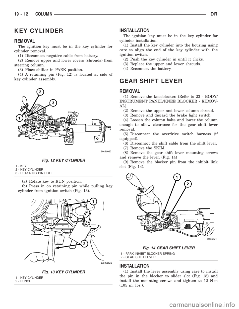
(4) A retaining pin (Fig. 12) is located at side of
key cylinder assembly.
(a) Rotate key to RUN position.
(b) Press in on retaining pin while pulling key
cylinder from ignition switch (Fig. 13).
INSTALLATION
The ignition key must be in the key cylinder for
cylinder installation.
(1) Install the key cylinder into the housing using
care to align the end of the key cylinder with the
ignition switch.
(2) Push the key cylinder in until it clicks.
(3) Replace the upper and lower shrouds.
(4) Reconnect the battery.
GEAR SHIFT LEVER
REMOVAL
(1) Remove the kneeblocker. (Refer to 23 - BODY/
INSTRUMENT PANEL/KNEE BLOCKER - REMOV-
AL).
(2) Remove the upper and lower column shroud.
(3) Remove and discard the brake light switch.
(4) Loosen the column bolts and lower the column
enough to allow clearance for the gear shift lever
removal.
(5) Disconnect the overdrive switch harness (if
equipped).
(6) Disconnect the shift cable from the shift lever.
(7) Remove the SKIM.
(8) Remove the gear shift lever mounting screws
and remove the lever. (Fig. 14)
(9) Remove the blocker pin from the inhibit link
slot (Fig. 14).
INSTALLATION
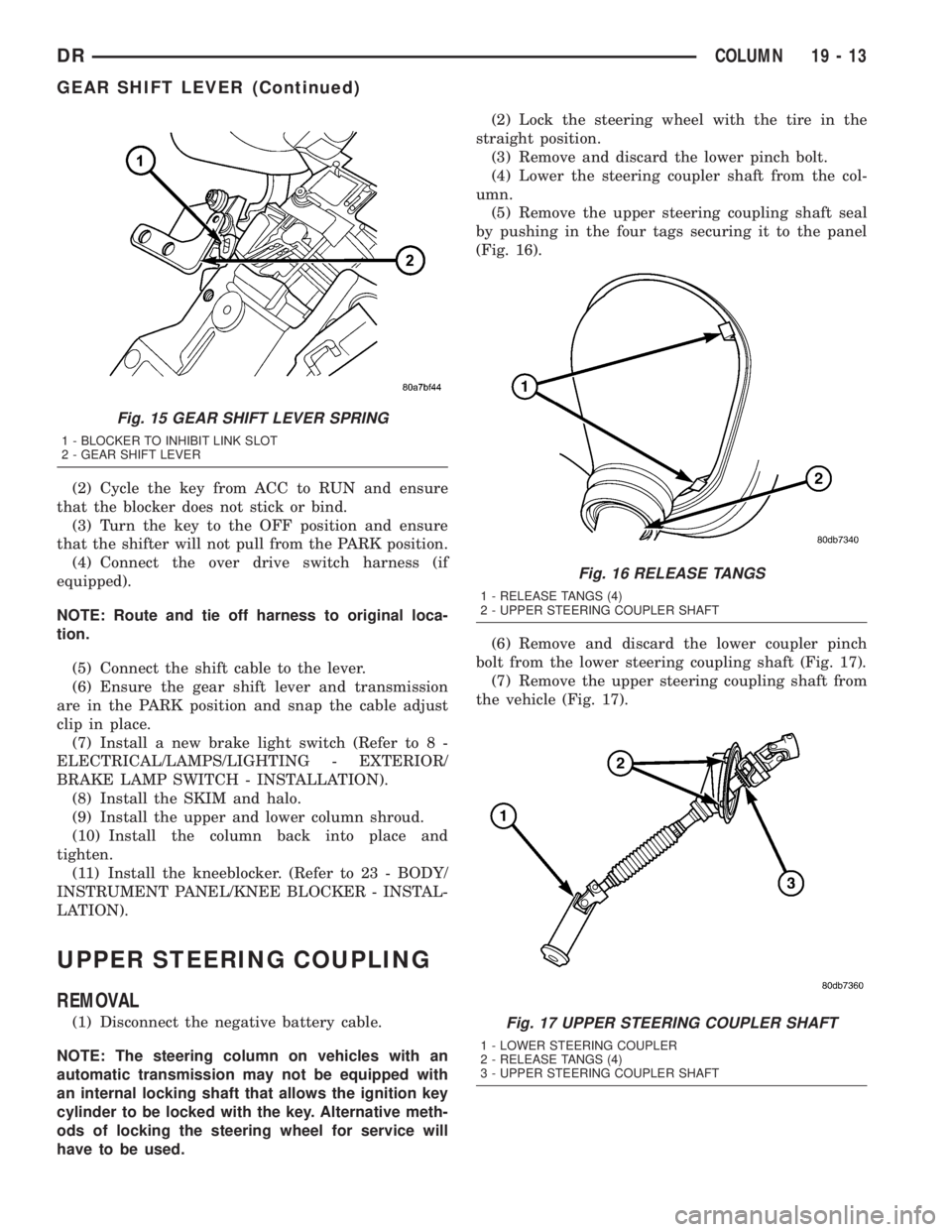
(1) Install the lever assembly using care to install
the pin in the blocker to slider slot (Fig. 15) and
install the mounting screws and tighten to 12 N´m
(105 in. lbs.).
Fig. 12 KEY CYLINDER
1 - KEY
2 - KEY CYLINDER
3 - RETAINING PIN HOLE
Fig. 13 KEY CYLINDER
1 - KEY CYLINDER
2 - PUNCH
Fig. 14 GEAR SHIFT LEVER
1 - PARK INHIBIT BLOCKER SPRING
2 - GEAR SHIFT LEVER
19 - 12 COLUMNDR
Page 1806 of 2895
(2) Cycle the key from ACC to RUN and ensure
that the blocker does not stick or bind.
(3) Turn the key to the OFF position and ensure
that the shifter will not pull from the PARK position.
(4) Connect the over drive switch harness (if
equipped).
NOTE: Route and tie off harness to original loca-
tion.
(5) Connect the shift cable to the lever.
(6) Ensure the gear shift lever and transmission
are in the PARK position and snap the cable adjust
clip in place.
(7) Install a new brake light switch (Refer to 8 -
ELECTRICAL/LAMPS/LIGHTING - EXTERIOR/
BRAKE LAMP SWITCH - INSTALLATION).
(8) Install the SKIM and halo.
(9) Install the upper and lower column shroud.
(10) Install the column back into place and
tighten.
(11) Install the kneeblocker. (Refer to 23 - BODY/
INSTRUMENT PANEL/KNEE BLOCKER - INSTAL-
LATION).
UPPER STEERING COUPLING
REMOVAL
(1) Disconnect the negative battery cable.
NOTE: The steering column on vehicles with an
automatic transmission may not be equipped with
an internal locking shaft that allows the ignition key
cylinder to be locked with the key. Alternative meth-
ods of locking the steering wheel for service will
have to be used.(2) Lock the steering wheel with the tire in the
straight position.
(3) Remove and discard the lower pinch bolt.
(4) Lower the steering coupler shaft from the col-
umn.
(5) Remove the upper steering coupling shaft seal
by pushing in the four tags securing it to the panel
(Fig. 16).
(6) Remove and discard the lower coupler pinch
bolt from the lower steering coupling shaft (Fig. 17).
(7) Remove the upper steering coupling shaft from
the vehicle (Fig. 17).
Fig. 15 GEAR SHIFT LEVER SPRING
1 - BLOCKER TO INHIBIT LINK SLOT
2 - GEAR SHIFT LEVER
Fig. 16 RELEASE TANGS
1 - RELEASE TANGS (4)
2 - UPPER STEERING COUPLER SHAFT
Fig. 17 UPPER STEERING COUPLER SHAFT
1 - LOWER STEERING COUPLER
2 - RELEASE TANGS (4)
3 - UPPER STEERING COUPLER SHAFT
DRCOLUMN 19 - 13
GEAR SHIFT LEVER (Continued)
Page 1807 of 2895
INSTALLATION
(1) Install the upper steering coupling shaft to the
vehicle (Fig. 17).
(2) Install the upper steering coupling shaft seal
by pushing it in securing the four tangs to the panel
(Fig. 16).
NOTE: Note: A new steering coupling shaft pinch
bolt for the upper and lower shafts must be used.
(3) Install the steering coupler shaft to the column
(Fig. 17).
(4) Install the upper pinch bolt use new bolt and
tighten to 57 N.m (42 ft.lbs).
(5) Install the shaft to the lower coupler (Fig. 17).
(6) Install the lower pinch bolt use new bolt and
tighten to 57 N.m (42 ft.lbs).
(7) Unlock the steering wheel.
(8) Reconnect the negative battery cable.
LOWER STEERING COUPLING
REMOVAL
REMOVAL - ALL LD & HD EXCEPT 4X4 HD
(1) Disconnect the negative battery cable.
(2) Raise and support the vehicle.
NOTE: The steering column on vehicles with an
automatic transmission may not be equipped with
an internal locking shaft that allows the ignition key
cylinder to be locked with the key. Alternative meth-
ods of locking the steering wheel for service will
have to be used.
(3) Lock the steering wheel with the tire in the
straight position.
(4) Remove the left front tire and wheel assembly.
(5) Mark both coupler connections for proper
installation.
(6) Remove and discard the upper coupler pinch
bolt.
(7) Remove and discard the lower coupler pinch
bolt.
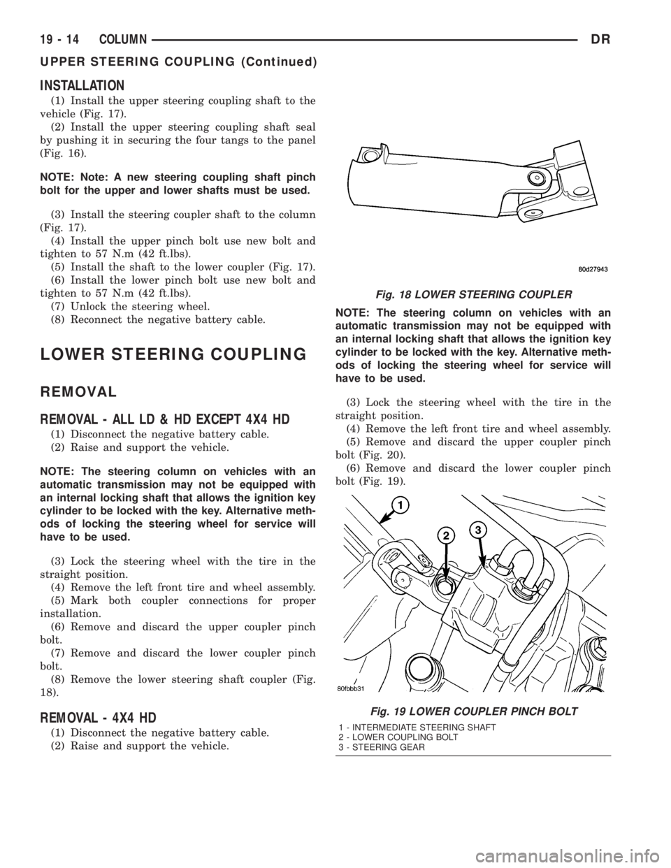
(8) Remove the lower steering shaft coupler (Fig.
18).
REMOVAL - 4X4 HD
(1) Disconnect the negative battery cable.
(2) Raise and support the vehicle.NOTE: The steering column on vehicles with an
automatic transmission may not be equipped with
an internal locking shaft that allows the ignition key
cylinder to be locked with the key. Alternative meth-
ods of locking the steering wheel for service will
have to be used.
(3) Lock the steering wheel with the tire in the
straight position.
(4) Remove the left front tire and wheel assembly.
(5) Remove and discard the upper coupler pinch
bolt (Fig. 20).
(6) Remove and discard the lower coupler pinch
bolt (Fig. 19).
Fig. 18 LOWER STEERING COUPLER
Fig. 19 LOWER COUPLER PINCH BOLT
1 - INTERMEDIATE STEERING SHAFT
2 - LOWER COUPLING BOLT
3 - STEERING GEAR
19 - 14 COLUMNDR
UPPER STEERING COUPLING (Continued)
Page 1809 of 2895
GEAR - INDEPENDENT FRONT SUSPENSION
TABLE OF CONTENTS
page page
GEAR - INDEPENDENT FRONT SUSPENSION
DESCRIPTION.........................16
REMOVAL.............................16
INSTALLATION.........................17
SPECIFICATIONS
TORQUE CHART......................18BUSHING
REMOVAL.............................18
INSTALLATION.........................18
GEAR - INDEPENDENT FRONT
SUSPENSION
DESCRIPTION
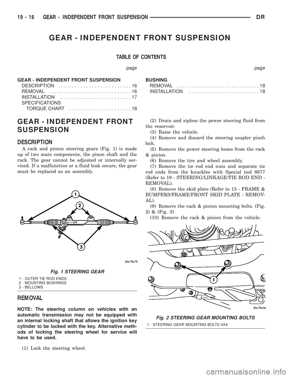
A rack and pinion steering gears (Fig. 1) is made
up of two main components, the pinon shaft and the
rack. The gear cannot be adjusted or internally ser-
viced. If a malfunction or a fluid leak occurs, the gear
must be replaced as an assembly.
REMOVAL
NOTE: The steering column on vehicles with an
automatic transmission may not be equipped with
an internal locking shaft that allows the ignition key
cylinder to be locked with the key. Alternative meth-
ods of locking the steering wheel for service will
have to be used.
(1) Lock the steering wheel.(2) Drain and siphon the power steering fluid from
the reservoir.
(3) Raise the vehicle.
(4) Remove and discard the steering coupler pinch
bolt.
(5) Remove the power steering hoses from the rack
& pinion.
(6) Remove the tire and wheel assembly.
(7) Remove the tie rod end nuts and separate tie
rod ends from the knuckles with Special tool 8677
(Refer to 19 - STEERING/LINKAGE/TIE ROD END -
REMOVAL).
(8) Remove the skid plate (Refer to 13 - FRAME &
BUMPERS/FRAME/FRONT SKID PLATE - REMOV-
AL).
(9) Remove the rack & pinion mounting bolts. (Fig.
2) & (Fig. 3)
(10) Remove the rack & pinion from the vehicle.
Fig. 1 STEERING GEAR
1 - OUTER TIE ROD ENDS
2 - MOUNTING BUSHINGS
3 - BELLOWS
Fig. 2 STEERING GEAR MOUNTING BOLTS
1 - STEERING GEAR MOUNTING BOLTS 4X4
19 - 16 GEAR - INDEPENDENT FRONT SUSPENSIONDR
Page 1812 of 2895
GEAR - LINK/COIL
TABLE OF CONTENTS
page page
GEAR - LINK/COIL
DESCRIPTION.........................19
OPERATION...........................19
REMOVAL.............................19
INSTALLATION.........................20
ADJUSTMENTS
ADJUSTMENT........................20
SPECIFICATIONS
POWER STEERING GEAR..............21
TORQUE CHART......................22
SPECIAL TOOLS
POWER STEERING GEAR..............22
PITMAN SHAFT SEAL
REMOVAL
REMOVAL - GAS ENGINE...............23REMOVAL - DIESEL...................24
INSTALLATION
INSTALLATION - GAS ENGINE...........24
INSTALLATION - DIESEL................25
STEERING GEAR INPUT SHAFT SEAL
REMOVAL.............................25
INSTALLATION.........................28
PITMAN SHAFT
REMOVAL
REMOVAL - GAS......................29
REMOVAL - DIESEL...................30
INSTALLATION
INSTALLATION - GAS..................30
INSTALLATION - DIESEL................30
GEAR - LINK/COIL
DESCRIPTION
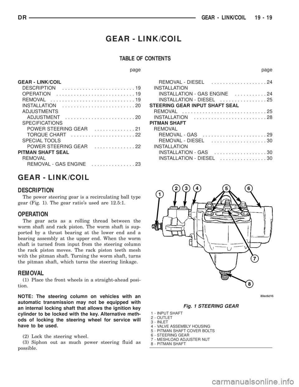
The power steering gear is a recirculating ball type
gear (Fig. 1). The gear ratio's used are 12.5:1.
OPERATION
The gear acts as a rolling thread between the
worm shaft and rack piston. The worm shaft is sup-
ported by a thrust bearing at the lower end and a
bearing assembly at the upper end. When the worm
shaft is turned from input from the steering column
the rack piston moves. The rack piston teeth mesh
with the pitman shaft. Turning the worm shaft, turns
the pitman shaft, which turns the steering linkage.
REMOVAL
(1) Place the front wheels in a straight-ahead posi-
tion.
NOTE: The steering column on vehicles with an
automatic transmission may not be equipped with
an internal locking shaft that allows the ignition key
cylinder to be locked with the key. Alternative meth-
ods of locking the steering wheel for service will
have to be used.
(2) Lock the steering wheel.
(3) Siphon out as much power steering fluid as
possible.
Fig. 1 STEERING GEAR
1 - INPUT SHAFT
2 - OUTLET
3 - INLET
4 - VALVE ASSEMBLY HOUSING
5 - PITMAN SHAFT COVER BOLTS
6 - STEERING GEAR
7 - MESHLOAD ADJUSTER NUT
8 - PITMAN SHAFT
DRGEAR - LINK/COIL 19 - 19
Page 1979 of 2895
CLUTCH AND BAND APPLICATION CHART
SHIFT
LEVER
POSITIONTRANSMISSION CLUTCHES AND BANDS OVERDRIVE CLUTCHES
FRONT
CLUTCHFRONT
BANDREAR
CLUTCHREAR
BANDOVER-
RUNNING
CLUTCHOVER-
DRIVE
CLUTCHDIRECT
CLUTCHOVER-
RUNNING
CLUTCH
Reverse X X X
Drive -
FirstXXXX
Drive -
SecondXX X X
Drive -
ThirdXX XX
Drive -
FourthXX X
Manual
SecondXX X X
Manual
FirstXXX X X
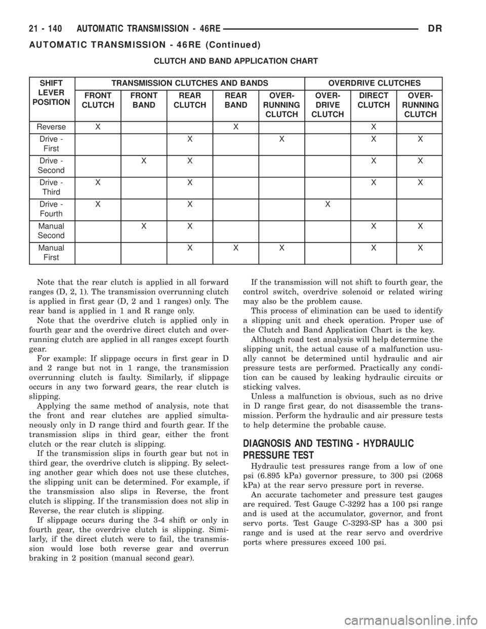
Note that the rear clutch is applied in all forward
ranges (D, 2, 1). The transmission overrunning clutch
is applied in first gear (D, 2 and 1 ranges) only. The
rear band is applied in 1 and R range only.
Note that the overdrive clutch is applied only in
fourth gear and the overdrive direct clutch and over-
running clutch are applied in all ranges except fourth
gear.
For example: If slippage occurs in first gear in D
and 2 range but not in 1 range, the transmission
overrunning clutch is faulty. Similarly, if slippage
occurs in any two forward gears, the rear clutch is
slipping.
Applying the same method of analysis, note that
the front and rear clutches are applied simulta-
neously only in D range third and fourth gear. If the
transmission slips in third gear, either the front
clutch or the rear clutch is slipping.
If the transmission slips in fourth gear but not in
third gear, the overdrive clutch is slipping. By select-
ing another gear which does not use these clutches,
the slipping unit can be determined. For example, if
the transmission also slips in Reverse, the front
clutch is slipping. If the transmission does not slip in
Reverse, the rear clutch is slipping.
If slippage occurs during the 3-4 shift or only in
fourth gear, the overdrive clutch is slipping. Simi-
larly, if the direct clutch were to fail, the transmis-
sion would lose both reverse gear and overrun
braking in 2 position (manual second gear).If the transmission will not shift to fourth gear, the
control switch, overdrive solenoid or related wiring
may also be the problem cause.
This process of elimination can be used to identify
a slipping unit and check operation. Proper use of
the Clutch and Band Application Chart is the key.
Although road test analysis will help determine the
slipping unit, the actual cause of a malfunction usu-
ally cannot be determined until hydraulic and air
pressure tests are performed. Practically any condi-
tion can be caused by leaking hydraulic circuits or
sticking valves.
Unless a malfunction is obvious, such as no drive
in D range first gear, do not disassemble the trans-
mission. Perform the hydraulic and air pressure tests
to help determine the probable cause.
DIAGNOSIS AND TESTING - HYDRAULIC
PRESSURE TEST
Hydraulic test pressures range from a low of one
psi (6.895 kPa) governor pressure, to 300 psi (2068
kPa) at the rear servo pressure port in reverse.
An accurate tachometer and pressure test gauges
are required. Test Gauge C-3292 has a 100 psi range
and is used at the accumulator, governor, and front
servo ports. Test Gauge C-3293-SP has a 300 psi
range and is used at the rear servo and overdrive
ports where pressures exceed 100 psi.
21 - 140 AUTOMATIC TRANSMISSION - 46REDR
AUTOMATIC TRANSMISSION - 46RE (Continued)
Page 2033 of 2895
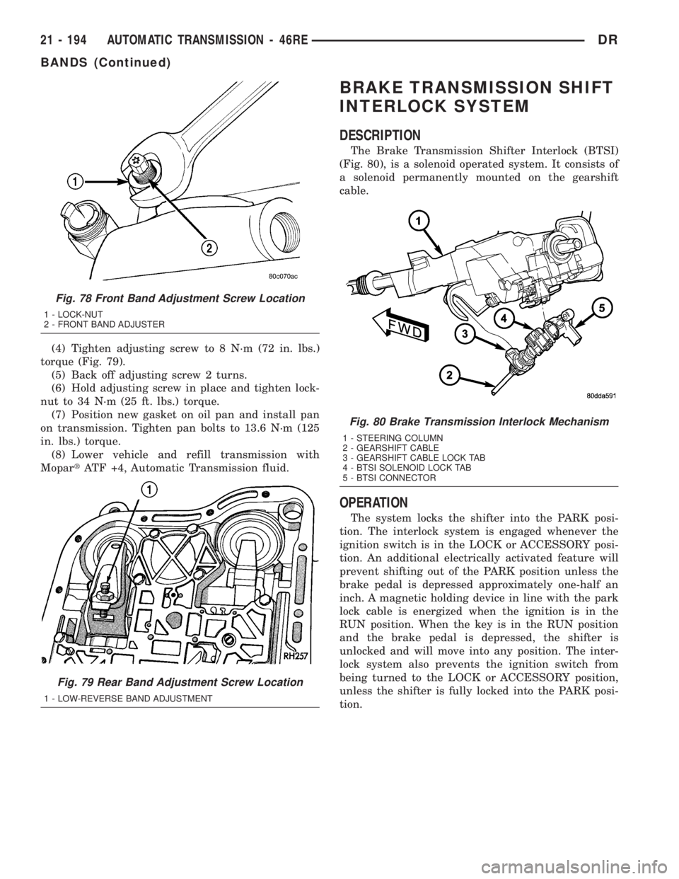
(4) Tighten adjusting screw to 8 N´m (72 in. lbs.)
torque (Fig. 79).
(5) Back off adjusting screw 2 turns.
(6) Hold adjusting screw in place and tighten lock-
nut to 34 N´m (25 ft. lbs.) torque.
(7) Position new gasket on oil pan and install pan
on transmission. Tighten pan bolts to 13.6 N´m (125
in. lbs.) torque.
(8) Lower vehicle and refill transmission with
MopartATF +4, Automatic Transmission fluid.
BRAKE TRANSMISSION SHIFT
INTERLOCK SYSTEM
DESCRIPTION
The Brake Transmission Shifter Interlock (BTSI)
(Fig. 80), is a solenoid operated system. It consists of
a solenoid permanently mounted on the gearshift
cable.
OPERATION
The system locks the shifter into the PARK posi-
tion. The interlock system is engaged whenever the
ignition switch is in the LOCK or ACCESSORY posi-
tion. An additional electrically activated feature will
prevent shifting out of the PARK position unless the
brake pedal is depressed approximately one-half an
inch. A magnetic holding device in line with the park
lock cable is energized when the ignition is in the
RUN position. When the key is in the RUN position
and the brake pedal is depressed, the shifter is
unlocked and will move into any position. The inter-
lock system also prevents the ignition switch from
being turned to the LOCK or ACCESSORY position,
unless the shifter is fully locked into the PARK posi-
tion.
Fig. 78 Front Band Adjustment Screw Location
1 - LOCK-NUT
2 - FRONT BAND ADJUSTER
Fig. 79 Rear Band Adjustment Screw Location
1 - LOW-REVERSE BAND ADJUSTMENT
Fig. 80 Brake Transmission Interlock Mechanism
1 - STEERING COLUMN
2 - GEARSHIFT CABLE
3 - GEARSHIFT CABLE LOCK TAB
4 - BTSI SOLENOID LOCK TAB
5 - BTSI CONNECTOR
21 - 194 AUTOMATIC TRANSMISSION - 46REDR
BANDS (Continued)