2003 DODGE RAM key
[x] Cancel search: keyPage 948 of 2895
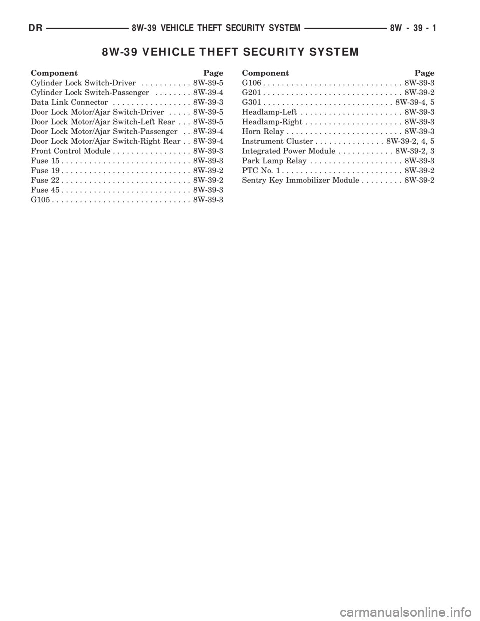
8W-39 VEHICLE THEFT SECURITY SYSTEM
Component Page
Cylinder Lock Switch-Driver........... 8W-39-5
Cylinder Lock Switch-Passenger........ 8W-39-4
Data Link Connector................. 8W-39-3
Door Lock Motor/Ajar Switch-Driver..... 8W-39-5
Door Lock Motor/Ajar Switch-Left Rear . . . 8W-39-5
Door Lock Motor/Ajar Switch-Passenger . . 8W-39-4
Door Lock Motor/Ajar Switch-Right Rear . . 8W-39-4
Front Control Module................. 8W-39-3
Fuse 15............................ 8W-39-3
Fuse 19............................ 8W-39-2
Fuse 22............................ 8W-39-2
Fuse 45............................ 8W-39-3
G105.............................. 8W-39-3Component Page
G106.............................. 8W-39-3
G201.............................. 8W-39-2
G301............................ 8W-39-4, 5
Headlamp-Left...................... 8W-39-3
Headlamp-Right..................... 8W-39-3
Horn Relay......................... 8W-39-3
Instrument Cluster............... 8W-39-2, 4, 5
Integrated Power Module............ 8W-39-2, 3
Park Lamp Relay.................... 8W-39-3
PTCNo.1.......................... 8W-39-2
Sentry Key Immobilizer Module......... 8W-39-2
DR8W-39 VEHICLE THEFT SECURITY SYSTEM 8W - 39 - 1
Page 1070 of 2895
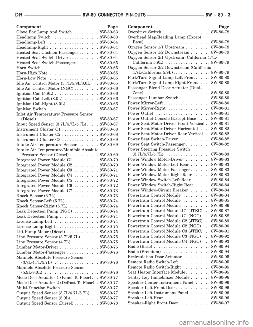
Component Page
Glove Box Lamp And Switch.......... 8W-80-63
Headlamp Switch................... 8W-80-63
Headlamp-Left..................... 8W-80-64
Headlamp-Right.................... 8W-80-64
Heated Seat Cushion-Passenger........ 8W-80-64
Heated Seat Switch-Driver............ 8W-80-64
Heated Seat Switch-Passenger......... 8W-80-65
Horn Switch....................... 8W-80-65
Horn-High Note.................... 8W-80-65
Horn-Low Note..................... 8W-80-65
Idle Air Control Motor (3.7L/5.9L/8.0L) . . 8W-80-65
Idle Air Control Motor (NGC).......... 8W-80-66
Ignition Coil (5.9L).................. 8W-80-66
Ignition Coil-Left (8.0L).............. 8W-80-66
Ignition Coil-Right (8.0L)............. 8W-80-66
Ignition Switch..................... 8W-80-67
Inlet Air Temperature/ Pressure Sensor
(Diesel)......................... 8W-80-67
Input Speed Sensor (3.7L/4.7L/5.7L)..... 8W-80-67
Instrument Cluster C1............... 8W-80-68
Instrument Cluster C2............... 8W-80-68
Instrument Cluster C3............... 8W-80-69
Intake Air Temperature Sensor........ 8W-80-69
Intake Air Temperature/Manifold Absolute
Pressure Sensor (Diesel)............ 8W-80-69
Integrated Power Module C1.......... 8W-80-70
Integrated Power Module C2.......... 8W-80-70
Integrated Power Module C3.......... 8W-80-71
Integrated Power Module C4.......... 8W-80-71
Integrated Power Module C5.......... 8W-80-72
Integrated Power Module C6.......... 8W-80-72
Integrated Power Module C7.......... 8W-80-73
Knock Sensor (3.7L)................. 8W-80-73
Knock Sensor-Left (5.7L)............. 8W-80-74
Knock Sensor-Right (5.7L)............ 8W-80-74
Leak Detection Pump (NGC).......... 8W-80-74
Leak Detection Pump................ 8W-80-74
License Lamp-Left.................. 8W-80-74
License Lamp-Right................. 8W-80-75
Lift Pump Motor (Diesel)............. 8W-80-75
Line Pressure Sensor (3.7L/5.7L)....... 8W-80-75
Line Pressure Sensor (4.7L)........... 8W-80-75
Lumbar Motor-Driver................ 8W-80-76
Lumbar Motor-Passenger............. 8W-80-76
Manifold Absolute Pressure Sensor
(3.7L/4.7L/5.7L).................. 8W-80-76
Manifold Absolute Pressure Sensor
(5.9L/8.0L)...................... 8W-80-76
Mode Door Actuator 1 (Panel To Floor) . . . 8W-80-77
Mode Door Actuator 2 (Defrost To Floor) . 8W-80-77
Multi-Function Switch............... 8W-80-77
Output Speed Sensor (3.7L/4.7L/5.7L) . . . 8W-80-77
Output Speed Sensor (5.9L)........... 8W-80-77
Output Speed Sensor (Diesel).......... 8W-80-78Component Page
Overdrive Switch................... 8W-80-78
Overhead Map/Reading Lamp (Except
Base).......................... 8W-80-78
Oxygen Sensor 1/1 Upstream.......... 8W-80-78
Oxygen Sensor 1/2 Downstream........ 8W-80-79
Oxygen Sensor 2/1 Upstream (California 4.7L/
California 5.9L).................. 8W-80-79
Oxygen Sensor 2/2 Downstream (California
4.7L/California 5.9L)............... 8W-80-79
Park/Turn Signal Lamp-Left Front...... 8W-80-80
Park/Turn Signal Lamp-Right Front.... 8W-80-80
Passenger Blend Door Actuator (Dual-
Zone).......................... 8W-80-80
Passenger Lumbar Switch............ 8W-80-80
Power Mirror-Left................... 8W-80-80
Power Mirror-Right................. 8W-80-81
Power Outlet...................... 8W-80-81
Power Outlet-Console (Except Base)..... 8W-80-81
Power Seat Motor-Driver Front Vertical . . 8W-80-81
Power Seat Motor-Driver Horizontal.... 8W-80-82
Power Seat Motor-Driver Rear Vertical . . 8W-80-82
Power Seat Switch-Driver............ 8W-80-82
Power Seat Switch-Passenger.......... 8W-80-82
Power Steering Pressure Switch
(3.7L/4.7L/5.7L).................. 8W-80-83
Power Window Motor-Driver.......... 8W-80-83
Power Window Motor-Left Rear........ 8W-80-83
Power Window Motor-Passenger........ 8W-80-83
Power Window Motor-Right Rear....... 8W-80-83
Power Window Switch-Left Rear....... 8W-80-84
Power Window Switch-Right Rear...... 8W-80-84
Power Window-Circuit Breaker........ 8W-80-84
Powertrain Control Module........... 8W-80-84
Powertrain Control Module........... 8W-80-85
Powertrain Control Module........... 8W-80-86
Powertrain Control Module C1 (JTEC) . . . 8W-80-87
Powertrain Control Module C1 (NGC) . . . 8W-80-88
Powertrain Control Module C2 (JTEC) . . . 8W-80-89
Powertrain Control Module C2 (NGC) . . . 8W-80-90
Powertrain Control Module C3 (JTEC) . . . 8W-80-91
Powertrain Control Module C3 (NGC) . . . 8W-80-92
Powertrain Control Module C4 (NGC) . . . 8W-80-93
Radio (Base)....................... 8W-80-94
Radio (Premium)................... 8W-80-94
Recirculation Door Actuator........... 8W-80-95
Remote Radio Switch-Left............ 8W-80-95
Remote Radio Switch-Right........... 8W-80-95
Seat Heater Interface Module.......... 8W-80-95
Sentry Key Immobilizer Module........ 8W-80-96
Speaker-Center Instrument Panel...... 8W-80-96
Speaker-Left Front Door.............. 8W-80-96
Speaker-Left Instrument Panel........ 8W-80-96
Speaker-Left Rear.................. 8W-80-96
Speaker-Right Front Door............ 8W-80-97
DR8W-80 CONNECTOR PIN-OUTS 8W - 80 - 3
Page 1134 of 2895
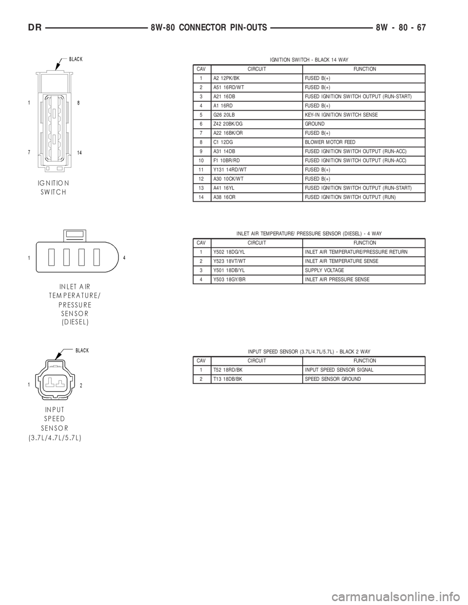
IGNITION SWITCH - BLACK 14 WAY
CAV CIRCUIT FUNCTION
1 A2 12PK/BK FUSED B(+)
2 A51 16RD/WT FUSED B(+)
3 A21 16DB FUSED IGNITION SWITCH OUTPUT (RUN-START)
4 A1 16RD FUSED B(+)
5 G26 20LB KEY-IN IGNITION SWITCH SENSE
6 Z42 20BK/DG GROUND
7 A22 16BK/OR FUSED B(+)
8 C1 12DG BLOWER MOTOR FEED
9 A31 14DB FUSED IGNITION SWITCH OUTPUT (RUN-ACC)
10 F1 10BR/RD FUSED IGNITION SWITCH OUTPUT (RUN-ACC)
11 Y131 14RD/WT FUSED B(+)
12 A30 10CK/WT FUSED B(+)
13 A41 16YL FUSED IGNITION SWITCH OUTPUT (RUN-START)
14 A38 16OR FUSED IGNITION SWITCH OUTPUT (RUN)
INLET AIR TEMPERATURE/ PRESSURE SENSOR (DIESEL)-4WAY
CAV CIRCUIT FUNCTION
1 Y502 18DG/YL INLET AIR TEMPERATURE/PRESSURE RETURN
2 Y523 18VT/WT INLET AIR TEMPERATURE SENSE
3 Y501 18DB/YL SUPPLY VOLTAGE
4 Y503 18GY/BR INLET AIR PRESSURE SENSE
INPUT SPEED SENSOR (3.7L/4.7L/5.7L) - BLACK 2 WAY
CAV CIRCUIT FUNCTION
1 T52 18RD/BK INPUT SPEED SENSOR SIGNAL
2 T13 18DB/BK SPEED SENSOR GROUND
DR8W-80 CONNECTOR PIN-OUTS 8W - 80 - 67
Page 1135 of 2895
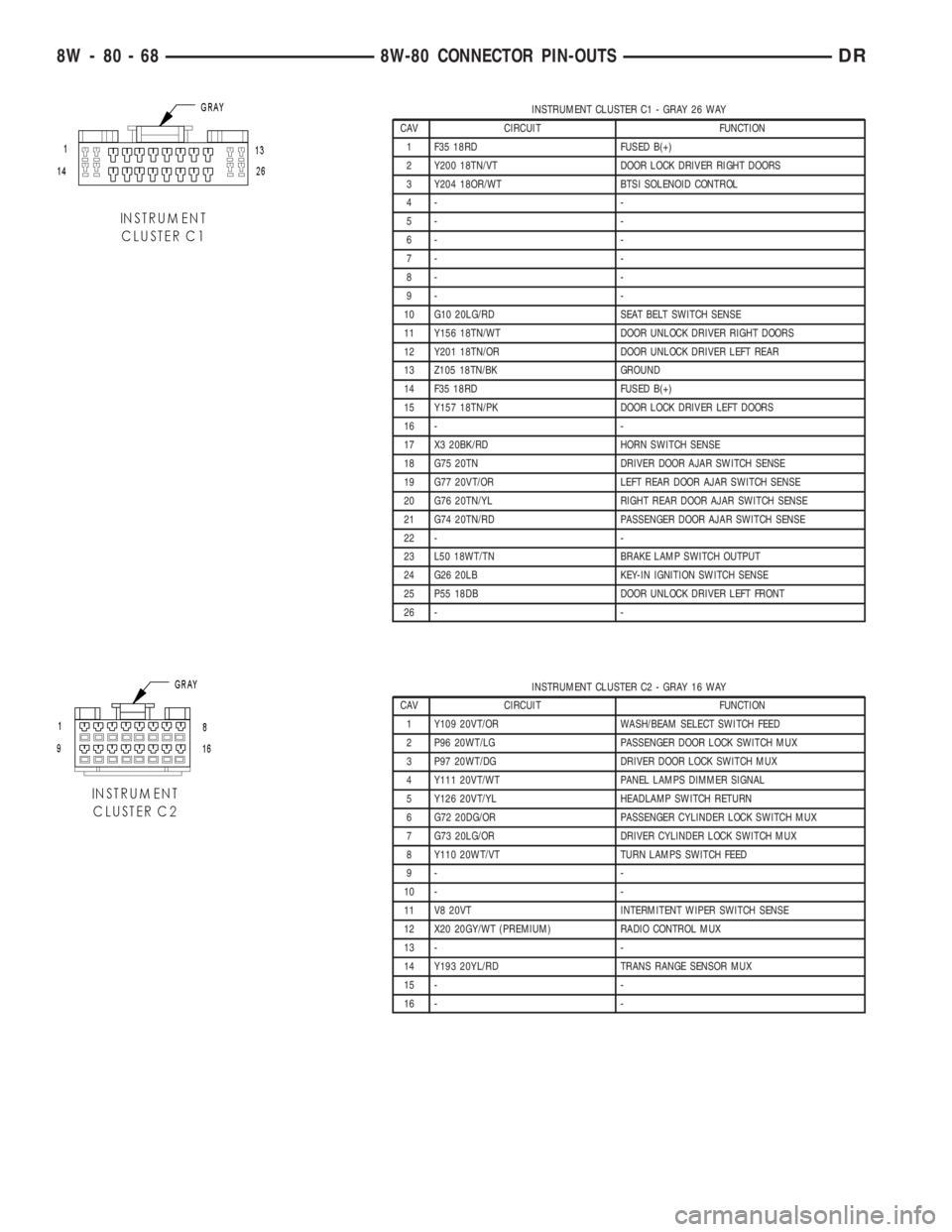
INSTRUMENT CLUSTER C1 - GRAY 26 WAY
CAV CIRCUIT FUNCTION
1 F35 18RD FUSED B(+)
2 Y200 18TN/VT DOOR LOCK DRIVER RIGHT DOORS
3 Y204 18OR/WT BTSI SOLENOID CONTROL
4- -
5- -
6- -
7- -
8- -
9- -
10 G10 20LG/RD SEAT BELT SWITCH SENSE
11 Y156 18TN/WT DOOR UNLOCK DRIVER RIGHT DOORS
12 Y201 18TN/OR DOOR UNLOCK DRIVER LEFT REAR
13 Z105 18TN/BK GROUND
14 F35 18RD FUSED B(+)
15 Y157 18TN/PK DOOR LOCK DRIVER LEFT DOORS
16 - -
17 X3 20BK/RD HORN SWITCH SENSE
18 G75 20TN DRIVER DOOR AJAR SWITCH SENSE
19 G77 20VT/OR LEFT REAR DOOR AJAR SWITCH SENSE
20 G76 20TN/YL RIGHT REAR DOOR AJAR SWITCH SENSE
21 G74 20TN/RD PASSENGER DOOR AJAR SWITCH SENSE
22 - -
23 L50 18WT/TN BRAKE LAMP SWITCH OUTPUT
24 G26 20LB KEY-IN IGNITION SWITCH SENSE
25 P55 18DB DOOR UNLOCK DRIVER LEFT FRONT
26 - -
INSTRUMENT CLUSTER C2 - GRAY 16 WAY
CAV CIRCUIT FUNCTION
1 Y109 20VT/OR WASH/BEAM SELECT SWITCH FEED
2 P96 20WT/LG PASSENGER DOOR LOCK SWITCH MUX
3 P97 20WT/DG DRIVER DOOR LOCK SWITCH MUX
4 Y111 20VT/WT PANEL LAMPS DIMMER SIGNAL
5 Y126 20VT/YL HEADLAMP SWITCH RETURN
6 G72 20DG/OR PASSENGER CYLINDER LOCK SWITCH MUX
7 G73 20LG/OR DRIVER CYLINDER LOCK SWITCH MUX
8 Y110 20WT/VT TURN LAMPS SWITCH FEED
9- -
10 - -
11 V8 20VT INTERMITENT WIPER SWITCH SENSE
12 X20 20GY/WT (PREMIUM) RADIO CONTROL MUX
13 - -
14 Y193 20YL/RD TRANS RANGE SENSOR MUX
15 - -
16 - -
8W - 80 - 68 8W-80 CONNECTOR PIN-OUTSDR
Page 1163 of 2895
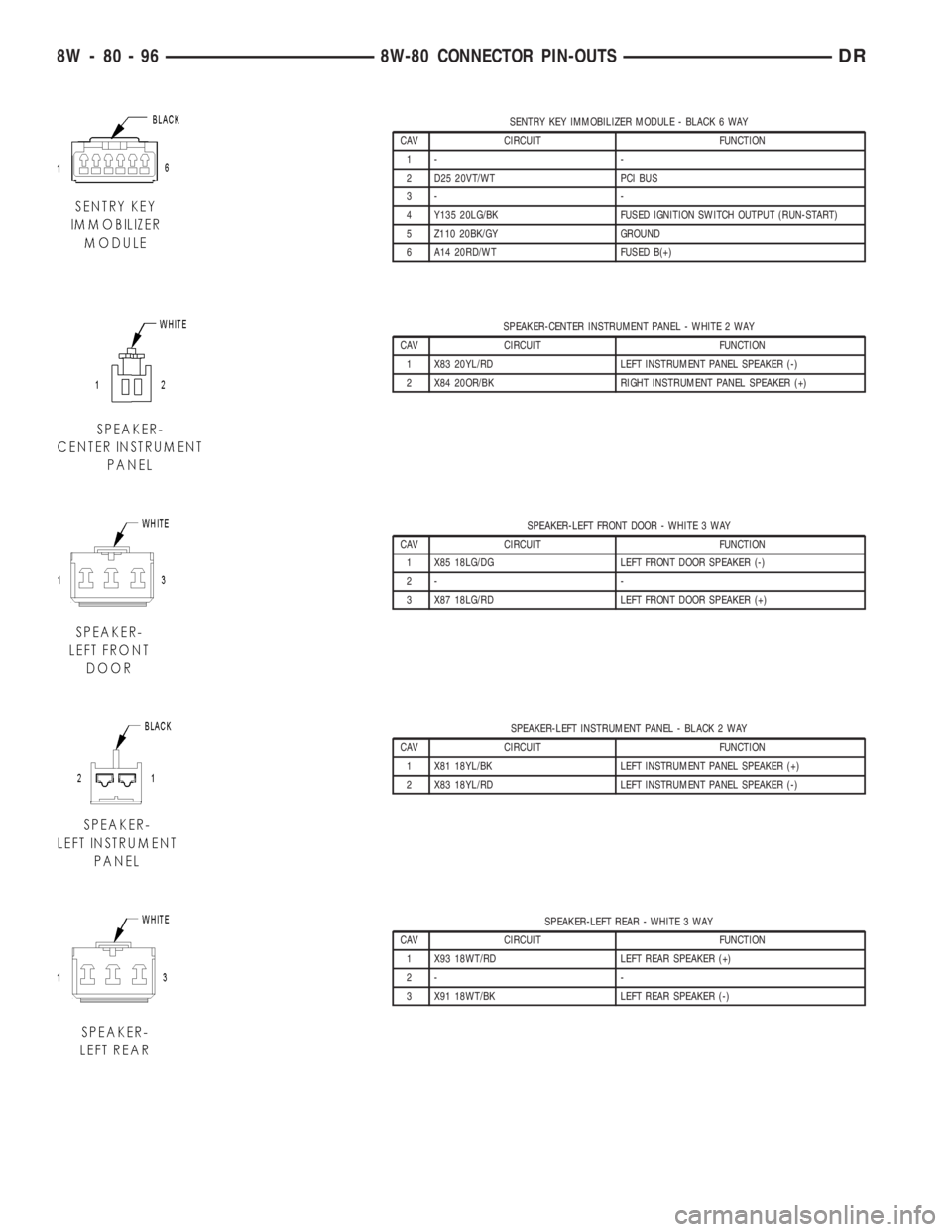
SENTRY KEY IMMOBILIZER MODULE - BLACK 6 WAY
CAV CIRCUIT FUNCTION
1- -
2 D25 20VT/WT PCI BUS
3- -
4 Y135 20LG/BK FUSED IGNITION SWITCH OUTPUT (RUN-START)
5 Z110 20BK/GY GROUND
6 A14 20RD/WT FUSED B(+)
SPEAKER-CENTER INSTRUMENT PANEL - WHITE 2 WAY
CAV CIRCUIT FUNCTION
1 X83 20YL/RD LEFT INSTRUMENT PANEL SPEAKER (-)
2 X84 20OR/BK RIGHT INSTRUMENT PANEL SPEAKER (+)
SPEAKER-LEFT FRONT DOOR - WHITE 3 WAY
CAV CIRCUIT FUNCTION
1 X85 18LG/DG LEFT FRONT DOOR SPEAKER (-)
2- -
3 X87 18LG/RD LEFT FRONT DOOR SPEAKER (+)
SPEAKER-LEFT INSTRUMENT PANEL - BLACK 2 WAY
CAV CIRCUIT FUNCTION
1 X81 18YL/BK LEFT INSTRUMENT PANEL SPEAKER (+)
2 X83 18YL/RD LEFT INSTRUMENT PANEL SPEAKER (-)
SPEAKER-LEFT REAR - WHITE 3 WAY
CAV CIRCUIT FUNCTION
1 X93 18WT/RD LEFT REAR SPEAKER (+)
2- -
3 X91 18WT/BK LEFT REAR SPEAKER (-)
8W - 80 - 96 8W-80 CONNECTOR PIN-OUTSDR
Page 1184 of 2895
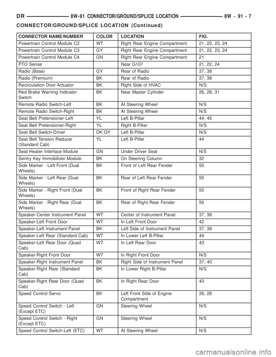
CONNECTOR NAME/NUMBER COLOR LOCATION FIG.
Powertrain Control Module C2 WT Right Rear Engine Compartment 21, 22, 23, 24
Powertrain Control Module C3 GY Right Rear Engine Compartment 21, 22, 23, 24
Powertrain Control Module C4 GN Right Rear Engine Compartment 21
PTO Sense Near G107 21, 22, 24
Radio (Base) GY Rear of Radio 37, 38
Radio (Premium) BK Rear of Radio 37, 38
Recirculation Door Actuator BK Right Side of HVAC N/S
Red Brake Warning Indicator
SwitchBK Near Master Cylinder 26, 28, 31
Remote Radio Switch-Left BK At Steering Wheel N/S
Remote Radio Switch-Right BK At Steering Wheel N/S
Seat Belt Pretensioner-Left YL Left B-Pillar 44, 45
Seat Belt Pretensioner-Right YL Right B-Pillar N/S
Seat Belt Switch-Driver DK GY Left B-Pillar N/S
Seat Belt Tension Reducer
(Standard Cab)YL Left B-Pillar 44
Seat Heater Interface Module GN Under Driver Seat N/S
Sentry Key Immobilizer Module BK On Steering Column 32
Side Marker - Left Front (Dual
Wheels)BK Front of Left Rear Fender 50
Side Marker - Left Rear (Dual
Wheels)BK Rear of Left Rear Fender 50
Side Marker - Right Front (Dual
Wheels)BK Front of Right Rear Fender 50
Side Marker - Right Rear (Dual
Wheels)BK Rear of Right Rear Fender 50
Speaker-Center Instrument Panel WT Center of Instrument Panel 37, 38
Speaker-Left Front Door WT In Left Front Door 42
Speaker-Left Instrument Panel BK Left Side of Instrument Panel 37, 39
Speaker-Left Rear (Standard Cab) WT In Lower Left B-Pillar 44
Speaker-Left Rear Door (Quad
Cab)WT In Left Rear Door 43
Speaker-Right Front Door WT In Right Front Door N/S
Speaker-Right Instrument Panel BK Right Side of Instrument Panel 37, 40
Speaker-Right Rear (Standard
Cab)BK In Lower Right B-Pillar N/S
Speaker-Right Rear Door (Quad
Cab)BK In Right Rear Door 43
Speed Control Servo BK Left Front Side of Engine
Compartment26, 28
Speed Control Switch - Left
(Except ETC)GN Steering Wheel N/S
Speed Control Switch - Right
(Except ETC)GN Steering Wheel N/S
Speed Control Switch-Left (ETC) WT At Steering Wheel N/S
DR8W-91 CONNECTOR/GROUND/SPLICE LOCATION 8W - 91 - 7
CONNECTOR/GROUND/SPLICE LOCATION (Continued)
Page 1304 of 2895
(8) Disconnect electrical connector for fan mounted
inside radiator shroud.
NOTE: Transmission cooler line snaps into shroud
lower right hand corner.
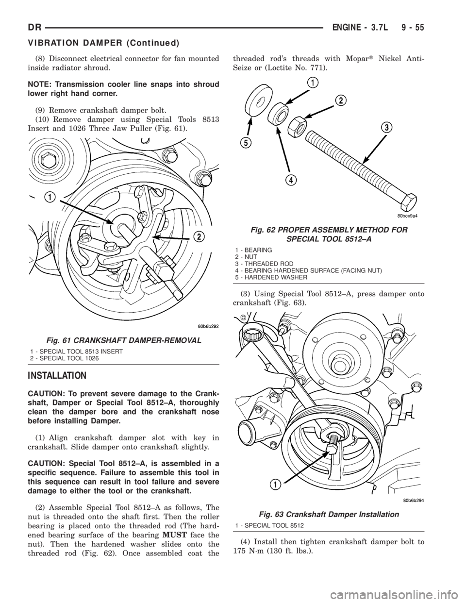
(9) Remove crankshaft damper bolt.
(10) Remove damper using Special Tools 8513
Insert and 1026 Three Jaw Puller (Fig. 61).
INSTALLATION
CAUTION: To prevent severe damage to the Crank-
shaft, Damper or Special Tool 8512±A, thoroughly
clean the damper bore and the crankshaft nose
before installing Damper.
(1) Align crankshaft damper slot with key in
crankshaft. Slide damper onto crankshaft slightly.
CAUTION: Special Tool 8512±A, is assembled in a
specific sequence. Failure to assemble this tool in
this sequence can result in tool failure and severe
damage to either the tool or the crankshaft.
(2) Assemble Special Tool 8512±A as follows, The
nut is threaded onto the shaft first. Then the roller
bearing is placed onto the threaded rod (The hard-
ened bearing surface of the bearingMUSTface the
nut). Then the hardened washer slides onto the
threaded rod (Fig. 62). Once assembled coat thethreaded rod's threads with MopartNickel Anti-
Seize or (Loctite No. 771).
(3) Using Special Tool 8512±A, press damper onto
crankshaft (Fig. 63).
(4) Install then tighten crankshaft damper bolt to
175 N´m (130 ft. lbs.).
Fig. 61 CRANKSHAFT DAMPER-REMOVAL
1 - SPECIAL TOOL 8513 INSERT
2 - SPECIAL TOOL 1026
Fig. 62 PROPER ASSEMBLY METHOD FOR
SPECIAL TOOL 8512±A
1 - BEARING
2 - NUT
3 - THREADED ROD
4 - BEARING HARDENED SURFACE (FACING NUT)
5 - HARDENED WASHER
Fig. 63 Crankshaft Damper Installation
1 - SPECIAL TOOL 8512
DRENGINE - 3.7L 9 - 55
VIBRATION DAMPER (Continued)
Page 1391 of 2895
NOTE: Transmission cooler line snaps into shroud
lower right hand corner.
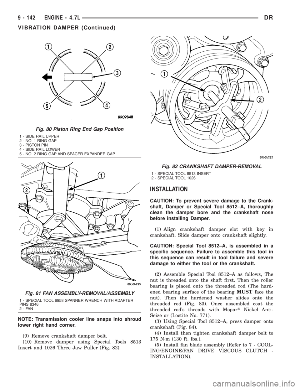
(9) Remove crankshaft damper bolt.
(10) Remove damper using Special Tools 8513
Insert and 1026 Three Jaw Puller (Fig. 82).
INSTALLATION
CAUTION: To prevent severe damage to the Crank-
shaft, Damper or Special Tool 8512±A, thoroughly
clean the damper bore and the crankshaft nose
before installing Damper.
(1) Align crankshaft damper slot with key in
crankshaft. Slide damper onto crankshaft slightly.
CAUTION: Special Tool 8512±A, is assembled in a
specific sequence. Failure to assemble this tool in
this sequence can result in tool failure and severe
damage to either the tool or the crankshaft.
(2) Assemble Special Tool 8512±A as follows, The
nut is threaded onto the shaft first. Then the roller
bearing is placed onto the threaded rod (The hard-
ened bearing surface of the bearingMUSTface the
nut). Then the hardened washer slides onto the
threaded rod (Fig. 83). Once assembled coat the
threaded rod's threads with MopartNickel Anti-
Seize or (Loctite No. 771).
(3) Using Special Tool 8512±A, press damper onto
crankshaft (Fig. 84).
(4) Install then tighten crankshaft damper bolt to
175 N´m (130 ft. lbs.).
(5) Install fan blade assembly (Refer to 7 - COOL-
ING/ENGINE/FAN DRIVE VISCOUS CLUTCH -
INSTALLATION).
Fig. 80 Piston Ring End Gap Position
1 - SIDE RAIL UPPER
2 - NO. 1 RING GAP
3 - PISTON PIN
4 - SIDE RAIL LOWER
5 - NO. 2 RING GAP AND SPACER EXPANDER GAP
Fig. 81 FAN ASSEMBLY-REMOVAL/ASSEMBLY
1 - SPECIAL TOOL 6958 SPANNER WRENCH WITH ADAPTER
PINS 8346
2-FAN
Fig. 82 CRANKSHAFT DAMPER-REMOVAL
1 - SPECIAL TOOL 8513 INSERT
2 - SPECIAL TOOL 1026
9 - 142 ENGINE - 4.7LDR
VIBRATION DAMPER (Continued)