2003 DODGE RAM water pump
[x] Cancel search: water pumpPage 1458 of 2895
(8) Install the oil ring expander.
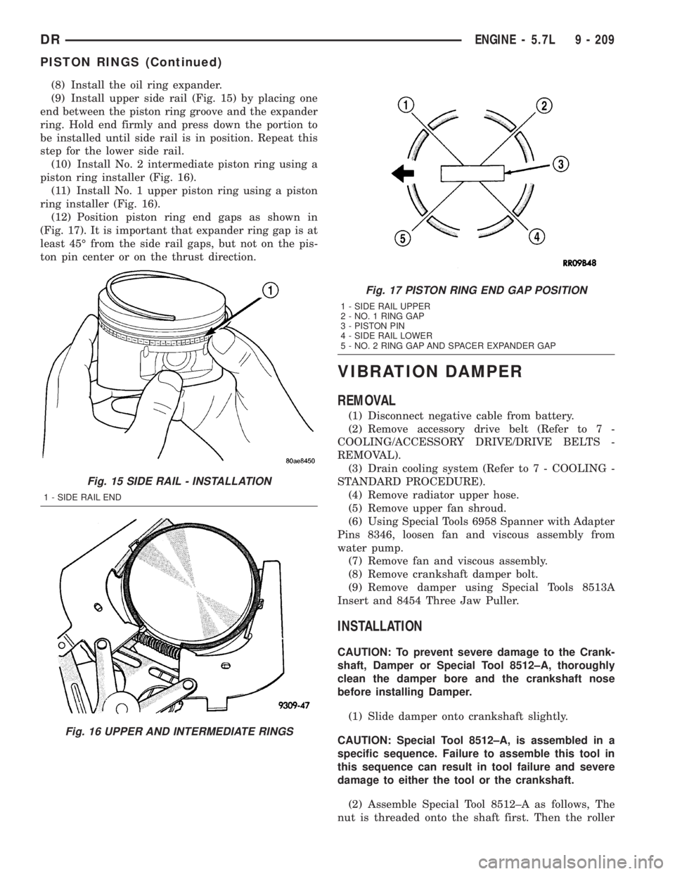
(9) Install upper side rail (Fig. 15) by placing one
end between the piston ring groove and the expander
ring. Hold end firmly and press down the portion to
be installed until side rail is in position. Repeat this
step for the lower side rail.
(10) Install No. 2 intermediate piston ring using a
piston ring installer (Fig. 16).
(11) Install No. 1 upper piston ring using a piston
ring installer (Fig. 16).
(12) Position piston ring end gaps as shown in
(Fig. 17). It is important that expander ring gap is at
least 45É from the side rail gaps, but not on the pis-
ton pin center or on the thrust direction.
VIBRATION DAMPER
REMOVAL
(1) Disconnect negative cable from battery.
(2) Remove accessory drive belt (Refer to 7 -
COOLING/ACCESSORY DRIVE/DRIVE BELTS -
REMOVAL).
(3) Drain cooling system (Refer to 7 - COOLING -
STANDARD PROCEDURE).
(4) Remove radiator upper hose.
(5) Remove upper fan shroud.
(6) Using Special Tools 6958 Spanner with Adapter
Pins 8346, loosen fan and viscous assembly from
water pump.
(7) Remove fan and viscous assembly.
(8) Remove crankshaft damper bolt.
(9) Remove damper using Special Tools 8513A
Insert and 8454 Three Jaw Puller.
INSTALLATION
CAUTION: To prevent severe damage to the Crank-
shaft, Damper or Special Tool 8512±A, thoroughly
clean the damper bore and the crankshaft nose
before installing Damper.
(1) Slide damper onto crankshaft slightly.
CAUTION: Special Tool 8512±A, is assembled in a
specific sequence. Failure to assemble this tool in
this sequence can result in tool failure and severe
damage to either the tool or the crankshaft.
(2) Assemble Special Tool 8512±A as follows, The
nut is threaded onto the shaft first. Then the roller
Fig. 15 SIDE RAIL - INSTALLATION
1 - SIDE RAIL END
Fig. 16 UPPER AND INTERMEDIATE RINGS
Fig. 17 PISTON RING END GAP POSITION
1 - SIDE RAIL UPPER
2 - NO. 1 RING GAP
3 - PISTON PIN
4 - SIDE RAIL LOWER
5 - NO. 2 RING GAP AND SPACER EXPANDER GAP
DRENGINE - 5.7L 9 - 209
PISTON RINGS (Continued)
Page 1468 of 2895
INSTALLATION
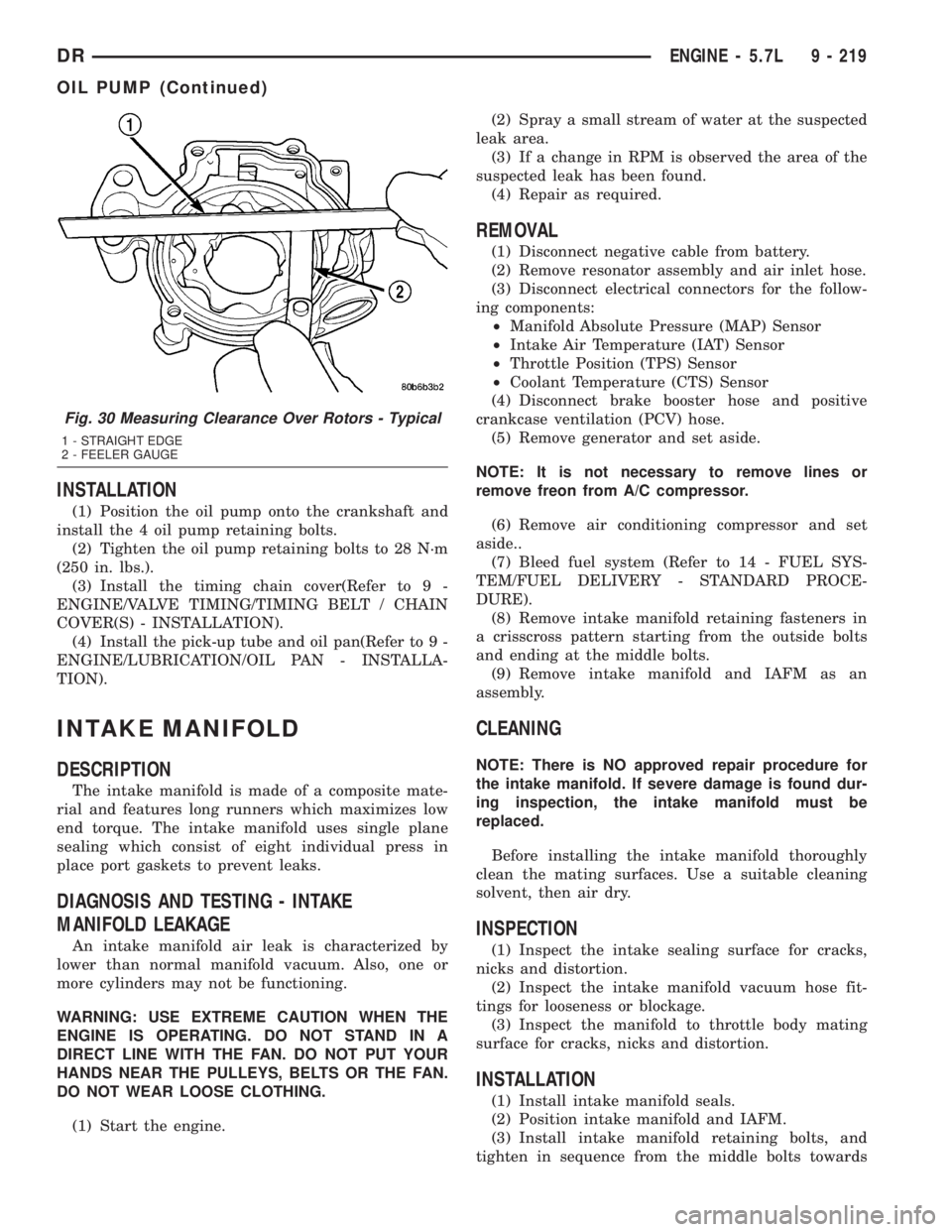
(1) Position the oil pump onto the crankshaft and
install the 4 oil pump retaining bolts.
(2) Tighten the oil pump retaining bolts to 28 N´m
(250 in. lbs.).
(3) Install the timing chain cover(Refer to 9 -
ENGINE/VALVE TIMING/TIMING BELT / CHAIN
COVER(S) - INSTALLATION).
(4) Install the pick-up tube and oil pan(Refer to 9 -
ENGINE/LUBRICATION/OIL PAN - INSTALLA-
TION).
INTAKE MANIFOLD
DESCRIPTION
The intake manifold is made of a composite mate-
rial and features long runners which maximizes low
end torque. The intake manifold uses single plane
sealing which consist of eight individual press in
place port gaskets to prevent leaks.
DIAGNOSIS AND TESTING - INTAKE
MANIFOLD LEAKAGE
An intake manifold air leak is characterized by
lower than normal manifold vacuum. Also, one or
more cylinders may not be functioning.
WARNING: USE EXTREME CAUTION WHEN THE
ENGINE IS OPERATING. DO NOT STAND IN A
DIRECT LINE WITH THE FAN. DO NOT PUT YOUR
HANDS NEAR THE PULLEYS, BELTS OR THE FAN.
DO NOT WEAR LOOSE CLOTHING.
(1) Start the engine.(2) Spray a small stream of water at the suspected
leak area.
(3) If a change in RPM is observed the area of the
suspected leak has been found.
(4) Repair as required.
REMOVAL
(1) Disconnect negative cable from battery.
(2) Remove resonator assembly and air inlet hose.
(3) Disconnect electrical connectors for the follow-
ing components:
²Manifold Absolute Pressure (MAP) Sensor
²Intake Air Temperature (IAT) Sensor
²Throttle Position (TPS) Sensor
²Coolant Temperature (CTS) Sensor
(4) Disconnect brake booster hose and positive
crankcase ventilation (PCV) hose.
(5) Remove generator and set aside.
NOTE: It is not necessary to remove lines or
remove freon from A/C compressor.
(6) Remove air conditioning compressor and set
aside..
(7) Bleed fuel system (Refer to 14 - FUEL SYS-
TEM/FUEL DELIVERY - STANDARD PROCE-
DURE).
(8) Remove intake manifold retaining fasteners in
a crisscross pattern starting from the outside bolts
and ending at the middle bolts.
(9) Remove intake manifold and IAFM as an
assembly.
CLEANING
NOTE: There is NO approved repair procedure for
the intake manifold. If severe damage is found dur-
ing inspection, the intake manifold must be
replaced.
Before installing the intake manifold thoroughly
clean the mating surfaces. Use a suitable cleaning
solvent, then air dry.
INSPECTION
(1) Inspect the intake sealing surface for cracks,
nicks and distortion.
(2) Inspect the intake manifold vacuum hose fit-
tings for looseness or blockage.
(3) Inspect the manifold to throttle body mating
surface for cracks, nicks and distortion.
INSTALLATION
(1) Install intake manifold seals.
(2) Position intake manifold and IAFM.
(3) Install intake manifold retaining bolts, and
tighten in sequence from the middle bolts towards
Fig. 30 Measuring Clearance Over Rotors - Typical
1 - STRAIGHT EDGE
2 - FEELER GAUGE
DRENGINE - 5.7L 9 - 219
OIL PUMP (Continued)
Page 1470 of 2895
(14) Remove crankshaft damper(Refer to 9 -
ENGINE/ENGINE BLOCK/VIBRATION DAMPER -
REMOVAL).
NOTE: Do not remove the hoses from the power
steering pump.
(15) Remove power steering pump and set aside.
(16) Remove the dipstick support bolt.
(17) Drain the engine oil.
(18) Remove the oil pan and pick up tube(Refer to
9 - ENGINE/LUBRICATION/OIL PAN - REMOVAL).
NOTE: It is not necessary to remove water pump for
timing cover removal.
(19) Remove timing cover bolts and remove cover.
INSTALLATION
(1) Clean timing chain cover and block surface.
NOTE: Always install a new gasket on timing cover.
(2) Install cover and new gasket. Tighten fasteners
to 28 N´m (250 in. lbs.).
NOTE: The large lifting stud is torqued to 55 N´m
(40 ft. lbs.).
(3) Install the oil pan and pick up tube(Refer to 9 -
ENGINE/LUBRICATION/OIL PAN - INSTALLA-
TION).
(4) Install the A/C compressor.
(5) Install the generator.
(6) Install power steering pump.
(7) Install the dipstick support bolt.
(8) Install the thermostat housing.
(9) Install crankshaft damper(Refer to 9 -
ENGINE/ENGINE BLOCK/VIBRATION DAMPER -
INSTALLATION).
(10) Install accessory drive belt tensioner assembly
and both idler pulleys.
(11) Install radiator lower hose.
(12) Install both heater hoses.
(13) Install radiator fan shroud.
(14) Install the fan and fan drive assembly
(15) Install the accessory drive belt.
(16) Install the coolant bottle and washer bottle.
(17) Install the upper radiator hose.
(18) Install the air cleaner assembly.
(19) Fill cooling system.
(20) Refill engine oil.
(21) Connect the battery negative cable.
TIMING/CHAIN AND
SPROCKETS
REMOVAL
(1) Disconnect battery negative cable.
(2) Drain cooling system.
(3) Remove Timing Chain Cover.
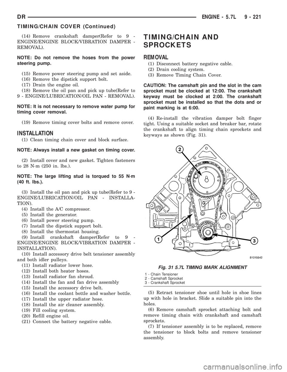
CAUTION: The camshaft pin and the slot in the cam
sprocket must be clocked at 12:00. The crankshaft
keyway must be clocked at 2:00. The crankshaft
sprocket must be installed so that the dots and or
paint marking is at 6:00.
(4) Re-install the vibration damper bolt finger
tight. Using a suitable socket and breaker bar, rotate
the crankshaft to align timing chain sprockets and
keyways as shown (Fig. 31).
(5) Retract tensioner shoe until hole in shoe lines
up with hole in bracket. Slide a suitable pin into the
holes.
(6) Remove camshaft sprocket attaching bolt and
remove timing chain with crankshaft and camshaft
sprockets.
(7) If tensioner assembly is to be replaced, remove
the tensioner to block bolts and remove tensioner
assembly.
Fig. 31 5.7L TIMING MARK ALIGNMENT
1 - Chain Tensioner
2 - Camshaft Sprocket
3 - Crankshaft Sprocket
DRENGINE - 5.7L 9 - 221
TIMING/CHAIN COVER (Continued)
Page 1475 of 2895
DIAGNOSIS AND TESTINGÐENGINE DIAGNOSIS - PERFORMANCE
PERFORMANCE DIAGNOSIS CHARTÐGASOLINE ENGINES
CONDITION POSSIBLE CAUSES CORRECTION
ENGINE WILL NOT CRANK 1. Weak or dead battery 1. Charge/Replace Battery. (Refer to 8 -
ELECTRICAL/BATTERY SYSTEM/
BATTERY - STANDARD PROCEDURE).
Check charging system. (Refer to 8 -
ELECTRICAL/CHARGING - DIAGNOSIS
AND TESTING).
2. Corroded or loose battery connections 2. Clean/tighten suspect battery/starter
connections
3. Faulty starter or related circuit(s) 3. Check starting system. (Refer to 8 -
ELECTRICAL/STARTING - DIAGNOSIS
AND TESTING)
4. Seized accessory drive component 4. Remove accessory drive belt and
attempt to start engine. If engine starts,
repair/replace seized component.
5. Engine internal mechanical failure or
hydro-static lock5. Refer to (Refer to 9 - ENGINE -
DIAGNOSIS AND TESTING)
ENGINE CRANKS BUT
WILL NOT START1. No spark 1. Check for spark. (Refer to 8 -
ELECTRICAL/IGNITION CONTROL -
DESCRIPTION)
2. No fuel 2. Perform fuel pressure test, and if
necessary, inspect fuel injector(s) and
driver circuits. (Refer to 14 - FUEL
SYSTEM/FUEL DELIVERY/FUEL PUMP -
DIAGNOSIS AND TESTING).
3. Low or no engine compression 3. Perform cylinder compression pressure
test. (Refer to 9 - ENGINE - DIAGNOSIS
AND TESTING).
ENGINE LOSS OF POWER 1. Worn or burned distributor rotor 1. Install new distributor rotor
2. Worn distributor shaft 2. Remove and repair distributor (Refer to
8 - ELECTRICAL/IGNITION CONTROL/
DISTRIBUTOR - REMOVAL).
3. Worn or incorrect gapped spark plugs 3. Clean plugs and set gap. (Refer to 8 -
ELECTRICAL/IGNITION CONTROL/
SPARK PLUG - CLEANING).
4. Dirt or water in fuel system 4. Clean system and replace fuel filter
5. Faulty fuel pump 5. Install new fuel pump
6. Incorrect valve timing 6. Correct valve timing
7. Blown cylinder head gasket 7. Install new cylinder head gasket
8. Low compression 8. Test cylinder compression (Refer to 9 -
ENGINE - DIAGNOSIS AND TESTING).
9. Burned, warped, or pitted valves 9. Install/Reface valves as necessary
10. Plugged or restricted exhaust system 10. Install new parts as necessary
11. Faulty ignition cables 11. Replace any cracked or shorted cables
9 - 226 ENGINE - 5.9LDR
ENGINE - 5.9L (Continued)
Page 1488 of 2895
OS-US Item Identification Location of
.127 mm adjacent to
two
(.005 in.) 3/89tapped
holes on
each
end of
cylinder
head.
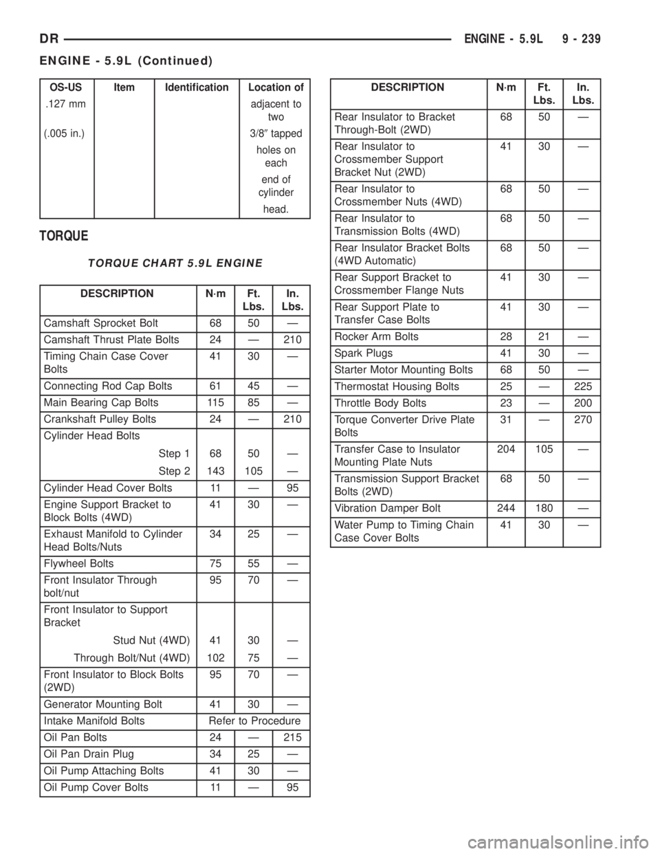
TORQUE
TORQUE CHART 5.9L ENGINE
DESCRIPTION N´m Ft.
Lbs.In.
Lbs.
Camshaft Sprocket Bolt 68 50 Ð
Camshaft Thrust Plate Bolts 24 Ð 210
Timing Chain Case Cover
Bolts41 30 Ð
Connecting Rod Cap Bolts 61 45 Ð
Main Bearing Cap Bolts 115 85 Ð
Crankshaft Pulley Bolts 24 Ð 210
Cylinder Head Bolts
Step 1 68 50 Ð
Step 2 143 105 Ð
Cylinder Head Cover Bolts 11 Ð 95
Engine Support Bracket to
Block Bolts (4WD)41 30 Ð
Exhaust Manifold to Cylinder
Head Bolts/Nuts34 25 Ð
Flywheel Bolts 75 55 Ð
Front Insulator Through
bolt/nut95 70 Ð
Front Insulator to Support
Bracket
Stud Nut (4WD) 41 30 Ð
Through Bolt/Nut (4WD) 102 75 Ð
Front Insulator to Block Bolts
(2WD)95 70 Ð
Generator Mounting Bolt 41 30 Ð
Intake Manifold Bolts Refer to Procedure
Oil Pan Bolts 24 Ð 215
Oil Pan Drain Plug 34 25 Ð
Oil Pump Attaching Bolts 41 30 Ð
Oil Pump Cover Bolts 11 Ð 95
DESCRIPTION N´m Ft.
Lbs.In.
Lbs.
Rear Insulator to Bracket
Through-Bolt (2WD)68 50 Ð
Rear Insulator to
Crossmember Support
Bracket Nut (2WD)41 30 Ð
Rear Insulator to
Crossmember Nuts (4WD)68 50 Ð
Rear Insulator to
Transmission Bolts (4WD)68 50 Ð
Rear Insulator Bracket Bolts
(4WD Automatic)68 50 Ð
Rear Support Bracket to
Crossmember Flange Nuts41 30 Ð
Rear Support Plate to
Transfer Case Bolts41 30 Ð
Rocker Arm Bolts 28 21 Ð
Spark Plugs 41 30 Ð
Starter Motor Mounting Bolts 68 50 Ð
Thermostat Housing Bolts 25 Ð 225
Throttle Body Bolts 23 Ð 200
Torque Converter Drive Plate
Bolts31 Ð 270
Transfer Case to Insulator
Mounting Plate Nuts204 105 Ð
Transmission Support Bracket
Bolts (2WD)68 50 Ð
Vibration Damper Bolt 244 180 Ð
Water Pump to Timing Chain
Case Cover Bolts41 30 Ð
DRENGINE - 5.9L 9 - 239
ENGINE - 5.9L (Continued)
Page 1527 of 2895
(5) Assemble exhaust pipe to manifold and secure
with bolts, nuts and retainers. Tighten the bolts and
nuts to 34 N´m (25 ft. lbs.) torque.
(6) Lower the vehicle.
(7) Connect the negative cable to the battery.
TIMING BELT / CHAIN
COVER(S)
REMOVAL
(1) Disconnect the negative cable from the battery.
(2) Remove water pump (Refer to 7 - COOLING/
ENGINE/WATER PUMP - REMOVAL).
(3) Remove power steering pump (Refer to 19 -
STEERING/PUMP - REMOVAL).
(4) Remove vibration damper (Refer to 9 -
ENGINE/ENGINE BLOCK/VIBRATION DAMPER -
REMOVAL).
(5) Loosen oil pan bolts and remove the front bolt
at each side.
(6) Remove the cover bolts.
(7) Remove chain case cover and gasket using
extreme caution to avoid damaging oil pan gasket.
INSTALLATION
(1) Be sure mating surfaces of chain case cover
and cylinder block are clean and free from burrs.
(2) The water pump mounting surface must be
cleaned.
(3) Using a new cover gasket, carefully install
chain case cover to avoid damaging oil pan gasket.
Use a small amount of MopartSilicone Rubber Adhe-
sive Sealant, or equivalent, at the joint between tim-
ing chain cover gasket and the oil pan gasket. Finger
tighten the timing chain cover bolts at this time.NOTE: Special Tool 6635 must be used to align the
front cover and seal with the crankshaft.
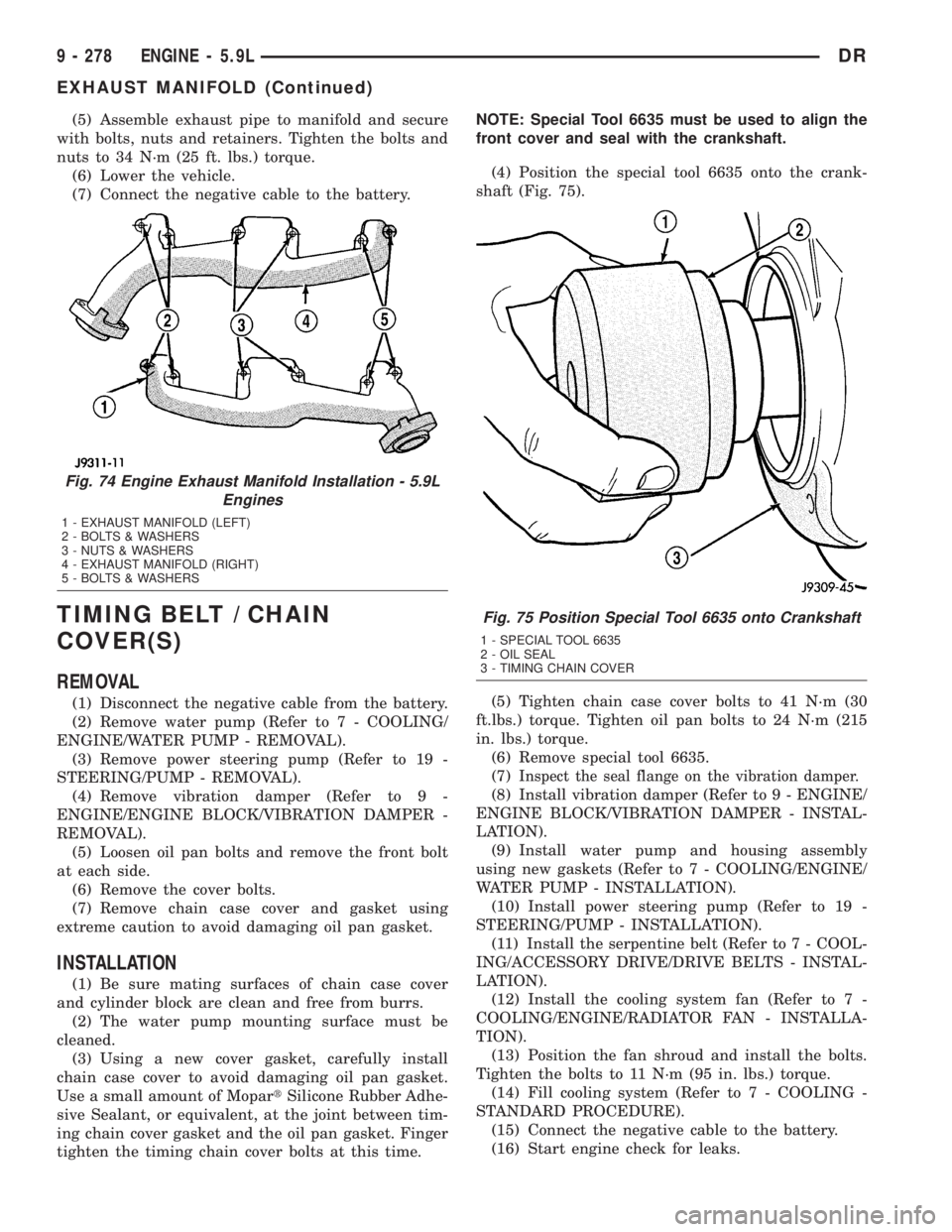
(4) Position the special tool 6635 onto the crank-
shaft (Fig. 75).
(5) Tighten chain case cover bolts to 41 N´m (30
ft.lbs.) torque. Tighten oil pan bolts to 24 N´m (215
in. lbs.) torque.
(6) Remove special tool 6635.
(7)
Inspect the seal flange on the vibration damper.
(8) Install vibration damper (Refer to 9 - ENGINE/
ENGINE BLOCK/VIBRATION DAMPER - INSTAL-
LATION).
(9) Install water pump and housing assembly
using new gaskets (Refer to 7 - COOLING/ENGINE/
WATER PUMP - INSTALLATION).
(10) Install power steering pump (Refer to 19 -
STEERING/PUMP - INSTALLATION).
(11) Install the serpentine belt (Refer to 7 - COOL-
ING/ACCESSORY DRIVE/DRIVE BELTS - INSTAL-
LATION).
(12) Install the cooling system fan (Refer to 7 -
COOLING/ENGINE/RADIATOR FAN - INSTALLA-
TION).
(13) Position the fan shroud and install the bolts.
Tighten the bolts to 11 N´m (95 in. lbs.) torque.
(14) Fill cooling system (Refer to 7 - COOLING -
STANDARD PROCEDURE).
(15) Connect the negative cable to the battery.
(16) Start engine check for leaks.
Fig. 74 Engine Exhaust Manifold Installation - 5.9L
Engines
1 - EXHAUST MANIFOLD (LEFT)
2 - BOLTS & WASHERS
3 - NUTS & WASHERS
4 - EXHAUST MANIFOLD (RIGHT)
5 - BOLTS & WASHERS
Fig. 75 Position Special Tool 6635 onto Crankshaft
1 - SPECIAL TOOL 6635
2 - OIL SEAL
3 - TIMING CHAIN COVER
9 - 278 ENGINE - 5.9LDR
EXHAUST MANIFOLD (Continued)
Page 1533 of 2895
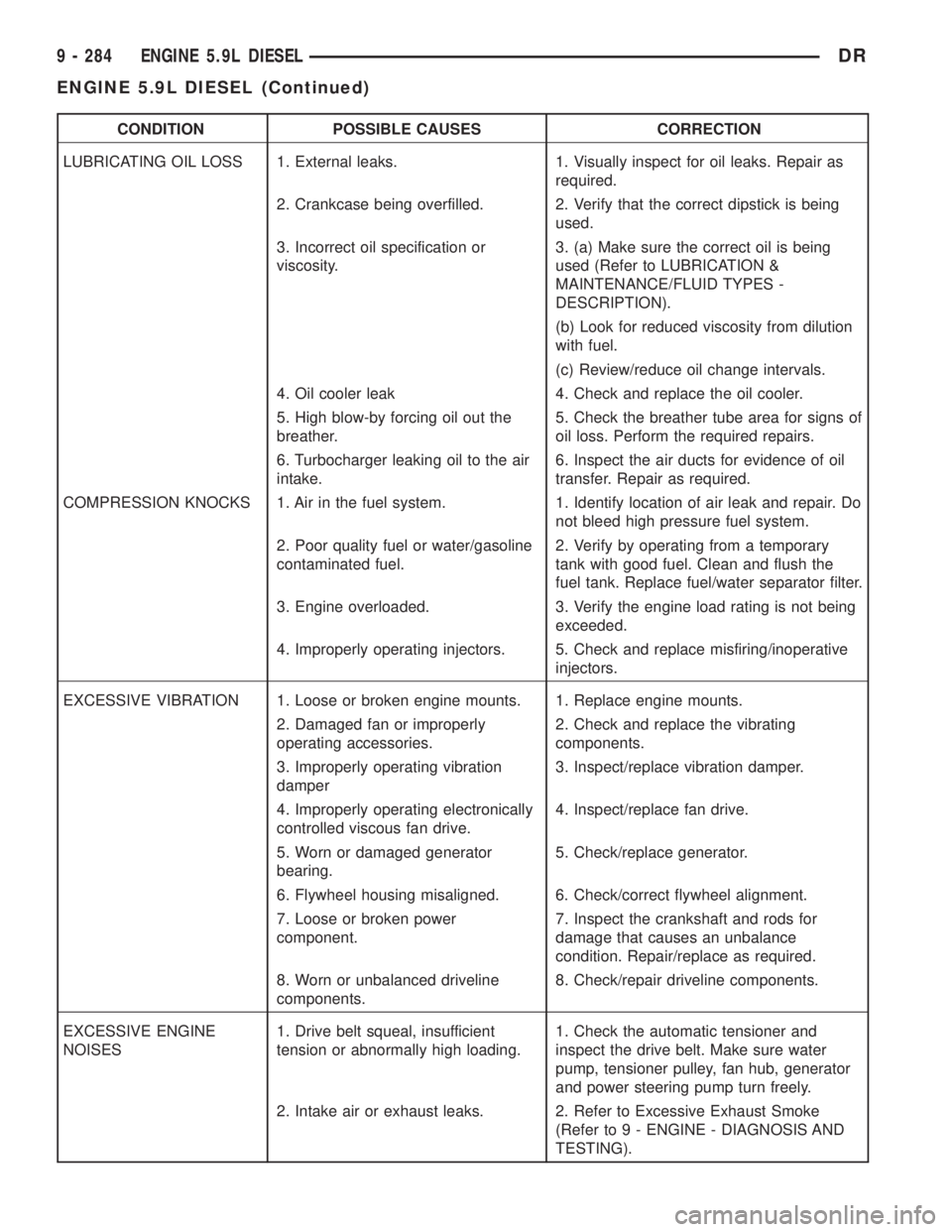
CONDITION POSSIBLE CAUSES CORRECTION
LUBRICATING OIL LOSS 1. External leaks. 1. Visually inspect for oil leaks. Repair as
required.
2. Crankcase being overfilled. 2. Verify that the correct dipstick is being
used.
3. Incorrect oil specification or
viscosity.3. (a) Make sure the correct oil is being
used (Refer to LUBRICATION &
MAINTENANCE/FLUID TYPES -
DESCRIPTION).
(b) Look for reduced viscosity from dilution
with fuel.
(c) Review/reduce oil change intervals.
4. Oil cooler leak 4. Check and replace the oil cooler.
5. High blow-by forcing oil out the
breather.5. Check the breather tube area for signs of
oil loss. Perform the required repairs.
6. Turbocharger leaking oil to the air
intake.6. Inspect the air ducts for evidence of oil
transfer. Repair as required.
COMPRESSION KNOCKS 1. Air in the fuel system. 1. Identify location of air leak and repair. Do
not bleed high pressure fuel system.
2. Poor quality fuel or water/gasoline
contaminated fuel.2. Verify by operating from a temporary
tank with good fuel. Clean and flush the
fuel tank. Replace fuel/water separator filter.
3. Engine overloaded. 3. Verify the engine load rating is not being
exceeded.
4. Improperly operating injectors. 5. Check and replace misfiring/inoperative
injectors.
EXCESSIVE VIBRATION 1. Loose or broken engine mounts. 1. Replace engine mounts.
2. Damaged fan or improperly
operating accessories.2. Check and replace the vibrating
components.
3. Improperly operating vibration
damper3. Inspect/replace vibration damper.
4. Improperly operating electronically
controlled viscous fan drive.4. Inspect/replace fan drive.
5. Worn or damaged generator
bearing.5. Check/replace generator.
6. Flywheel housing misaligned. 6. Check/correct flywheel alignment.
7. Loose or broken power
component.7. Inspect the crankshaft and rods for
damage that causes an unbalance
condition. Repair/replace as required.
8. Worn or unbalanced driveline
components.8. Check/repair driveline components.
EXCESSIVE ENGINE
NOISES1. Drive belt squeal, insufficient
tension or abnormally high loading.1. Check the automatic tensioner and
inspect the drive belt. Make sure water
pump, tensioner pulley, fan hub, generator
and power steering pump turn freely.
2. Intake air or exhaust leaks. 2. Refer to Excessive Exhaust Smoke
(Refer to 9 - ENGINE - DIAGNOSIS AND
TESTING).
9 - 284 ENGINE 5.9L DIESELDR
ENGINE 5.9L DIESEL (Continued)
Page 1537 of 2895
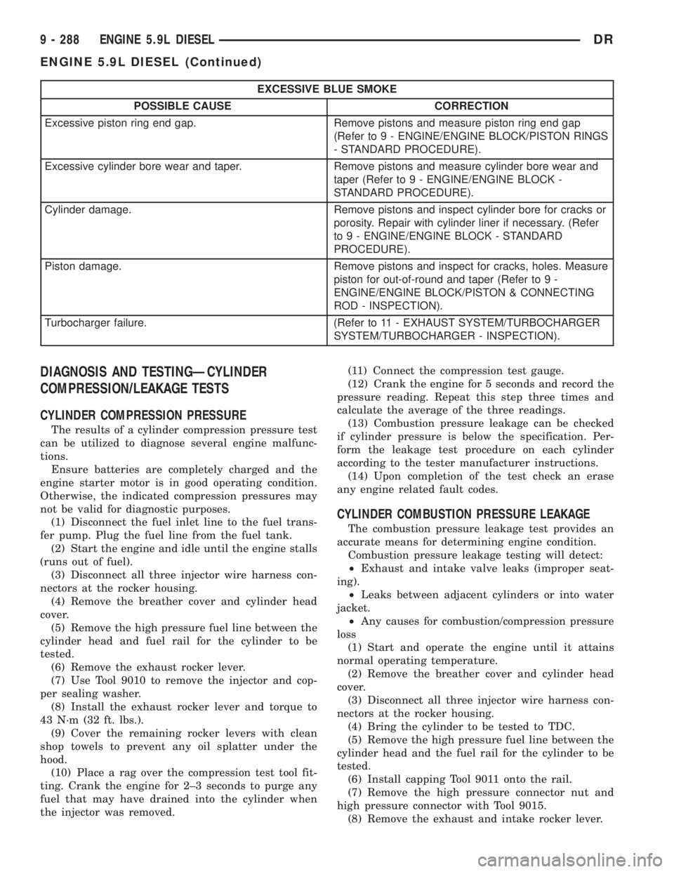
EXCESSIVE BLUE SMOKE
POSSIBLE CAUSE CORRECTION
Excessive piston ring end gap. Remove pistons and measure piston ring end gap
(Refer to 9 - ENGINE/ENGINE BLOCK/PISTON RINGS
- STANDARD PROCEDURE).
Excessive cylinder bore wear and taper. Remove pistons and measure cylinder bore wear and
taper (Refer to 9 - ENGINE/ENGINE BLOCK -
STANDARD PROCEDURE).
Cylinder damage. Remove pistons and inspect cylinder bore for cracks or
porosity. Repair with cylinder liner if necessary. (Refer
to 9 - ENGINE/ENGINE BLOCK - STANDARD
PROCEDURE).
Piston damage. Remove pistons and inspect for cracks, holes. Measure
piston for out-of-round and taper (Refer to 9 -
ENGINE/ENGINE BLOCK/PISTON & CONNECTING
ROD - INSPECTION).
Turbocharger failure. (Refer to 11 - EXHAUST SYSTEM/TURBOCHARGER
SYSTEM/TURBOCHARGER - INSPECTION).
DIAGNOSIS AND TESTINGÐCYLINDER
COMPRESSION/LEAKAGE TESTS
CYLINDER COMPRESSION PRESSURE
The results of a cylinder compression pressure test
can be utilized to diagnose several engine malfunc-
tions.
Ensure batteries are completely charged and the
engine starter motor is in good operating condition.
Otherwise, the indicated compression pressures may
not be valid for diagnostic purposes.
(1) Disconnect the fuel inlet line to the fuel trans-
fer pump. Plug the fuel line from the fuel tank.
(2) Start the engine and idle until the engine stalls
(runs out of fuel).
(3) Disconnect all three injector wire harness con-
nectors at the rocker housing.
(4) Remove the breather cover and cylinder head
cover.
(5) Remove the high pressure fuel line between the
cylinder head and fuel rail for the cylinder to be
tested.
(6) Remove the exhaust rocker lever.
(7) Use Tool 9010 to remove the injector and cop-
per sealing washer.
(8) Install the exhaust rocker lever and torque to
43 N´m (32 ft. lbs.).
(9) Cover the remaining rocker levers with clean
shop towels to prevent any oil splatter under the
hood.
(10) Place a rag over the compression test tool fit-
ting. Crank the engine for 2±3 seconds to purge any
fuel that may have drained into the cylinder when
the injector was removed.(11) Connect the compression test gauge.
(12) Crank the engine for 5 seconds and record the
pressure reading. Repeat this step three times and
calculate the average of the three readings.
(13) Combustion pressure leakage can be checked
if cylinder pressure is below the specification. Per-
form the leakage test procedure on each cylinder
according to the tester manufacturer instructions.
(14) Upon completion of the test check an erase
any engine related fault codes.
CYLINDER COMBUSTION PRESSURE LEAKAGE
The combustion pressure leakage test provides an
accurate means for determining engine condition.
Combustion pressure leakage testing will detect:
²Exhaust and intake valve leaks (improper seat-
ing).
²Leaks between adjacent cylinders or into water
jacket.
²Any causes for combustion/compression pressure
loss
(1) Start and operate the engine until it attains
normal operating temperature.
(2) Remove the breather cover and cylinder head
cover.
(3) Disconnect all three injector wire harness con-
nectors at the rocker housing.
(4) Bring the cylinder to be tested to TDC.
(5) Remove the high pressure fuel line between the
cylinder head and the fuel rail for the cylinder to be
tested.
(6) Install capping Tool 9011 onto the rail.
(7) Remove the high pressure connector nut and
high pressure connector with Tool 9015.
(8) Remove the exhaust and intake rocker lever.
9 - 288 ENGINE 5.9L DIESELDR
ENGINE 5.9L DIESEL (Continued)