2003 DODGE RAM water pump
[x] Cancel search: water pumpPage 353 of 2895
CAUTION: Do not pry water pump at timing chain
case/cover. The machined surfaces may be dam-
aged resulting in leaks.(9) Remove the water pump and gasket. Discard
gasket.
CLEANING
Clean the gasket mating surface. Use caution not
to damage the gasket sealing surface.
INSPECTION
Inspect the water pump assembly for cracks in the
housing, water leaks from shaft seal, worn bearing or
impeller rubbing either the pump body or timing
chain case/cover.
INSTALLATION
The water pump on 3.7L/4.7L engine is bolted
directly to the engine timing chain case cover.
(1) Clean the gasket mating surfaces.
(2) Using a new gasket, position water pump and
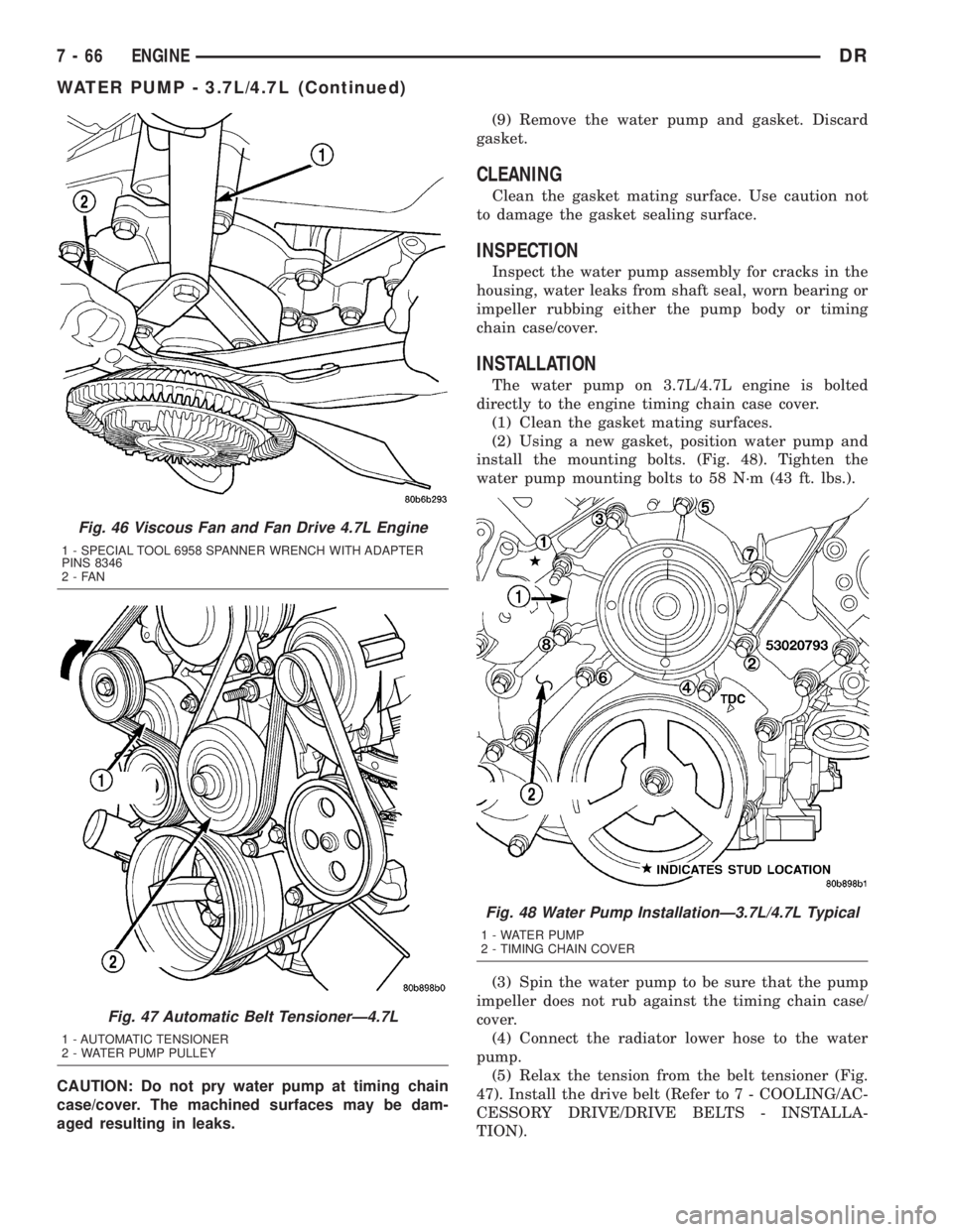
install the mounting bolts. (Fig. 48). Tighten the
water pump mounting bolts to 58 N´m (43 ft. lbs.).
(3) Spin the water pump to be sure that the pump
impeller does not rub against the timing chain case/
cover.
(4) Connect the radiator lower hose to the water
pump.
(5) Relax the tension from the belt tensioner (Fig.
47). Install the drive belt (Refer to 7 - COOLING/AC-
CESSORY DRIVE/DRIVE BELTS - INSTALLA-
TION).
Fig. 46 Viscous Fan and Fan Drive 4.7L Engine
1 - SPECIAL TOOL 6958 SPANNER WRENCH WITH ADAPTER
PINS 8346
2-FAN
Fig. 47 Automatic Belt TensionerÐ4.7L
1 - AUTOMATIC TENSIONER
2 - WATER PUMP PULLEY
Fig. 48 Water Pump InstallationÐ3.7L/4.7L Typical
1 - WATER PUMP
2 - TIMING CHAIN COVER
7 - 66 ENGINEDR
WATER PUMP - 3.7L/4.7L (Continued)
Page 354 of 2895
CAUTION: When installing the serpentine accessory
drive belt, the belt must be routed correctly. If not,
the engine may overheat due to the water pump
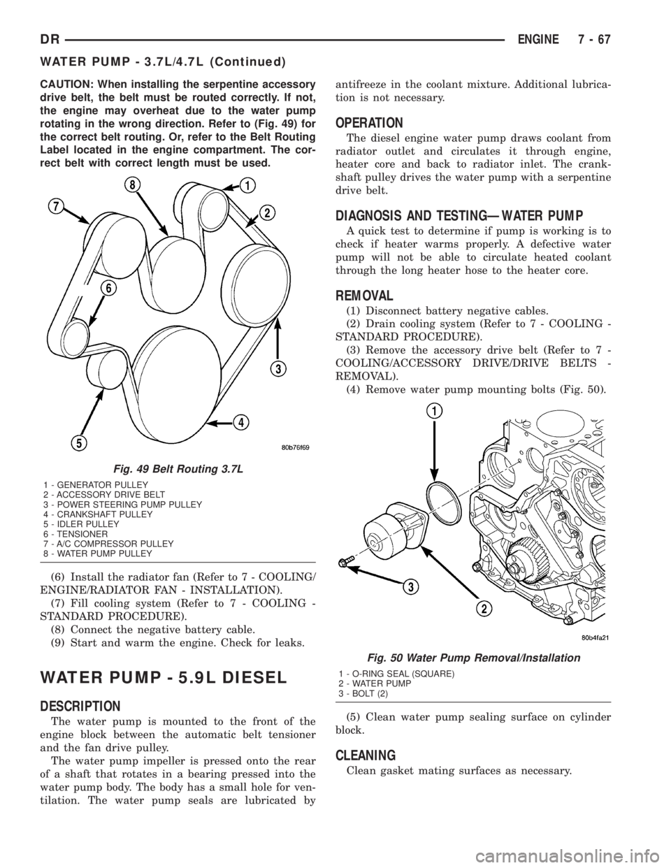
rotating in the wrong direction. Refer to (Fig. 49) for
the correct belt routing. Or, refer to the Belt Routing
Label located in the engine compartment. The cor-
rect belt with correct length must be used.
(6) Install the radiator fan (Refer to 7 - COOLING/
ENGINE/RADIATOR FAN - INSTALLATION).
(7) Fill cooling system (Refer to 7 - COOLING -
STANDARD PROCEDURE).
(8) Connect the negative battery cable.
(9) Start and warm the engine. Check for leaks.
WATER PUMP - 5.9L DIESEL
DESCRIPTION
The water pump is mounted to the front of the
engine block between the automatic belt tensioner
and the fan drive pulley.
The water pump impeller is pressed onto the rear
of a shaft that rotates in a bearing pressed into the
water pump body. The body has a small hole for ven-
tilation. The water pump seals are lubricated byantifreeze in the coolant mixture. Additional lubrica-
tion is not necessary.
OPERATION
The diesel engine water pump draws coolant from
radiator outlet and circulates it through engine,
heater core and back to radiator inlet. The crank-
shaft pulley drives the water pump with a serpentine
drive belt.
DIAGNOSIS AND TESTINGÐWATER PUMP
A quick test to determine if pump is working is to
check if heater warms properly. A defective water
pump will not be able to circulate heated coolant
through the long heater hose to the heater core.
REMOVAL
(1) Disconnect battery negative cables.
(2) Drain cooling system (Refer to 7 - COOLING -
STANDARD PROCEDURE).
(3) Remove the accessory drive belt (Refer to 7 -
COOLING/ACCESSORY DRIVE/DRIVE BELTS -
REMOVAL).
(4) Remove water pump mounting bolts (Fig. 50).
(5) Clean water pump sealing surface on cylinder
block.
CLEANING
Clean gasket mating surfaces as necessary.
Fig. 49 Belt Routing 3.7L
1 - GENERATOR PULLEY
2 - ACCESSORY DRIVE BELT
3 - POWER STEERING PUMP PULLEY
4 - CRANKSHAFT PULLEY
5 - IDLER PULLEY
6 - TENSIONER
7 - A/C COMPRESSOR PULLEY
8 - WATER PUMP PULLEY
Fig. 50 Water Pump Removal/Installation
1 - O-RING SEAL (SQUARE)
2 - WATER PUMP
3 - BOLT (2)
DRENGINE 7 - 67
WATER PUMP - 3.7L/4.7L (Continued)
Page 355 of 2895
INSPECTION
Visually inspect the water pump and replace if it
has any of the following conditions:
²The body is cracked or damaged
²Water leaks from the shaft seal. This is evident
by traces of coolant below the vent hole
²Loose or rough turning bearing.
²Impeller rubbing the pump body
INSTALLATION
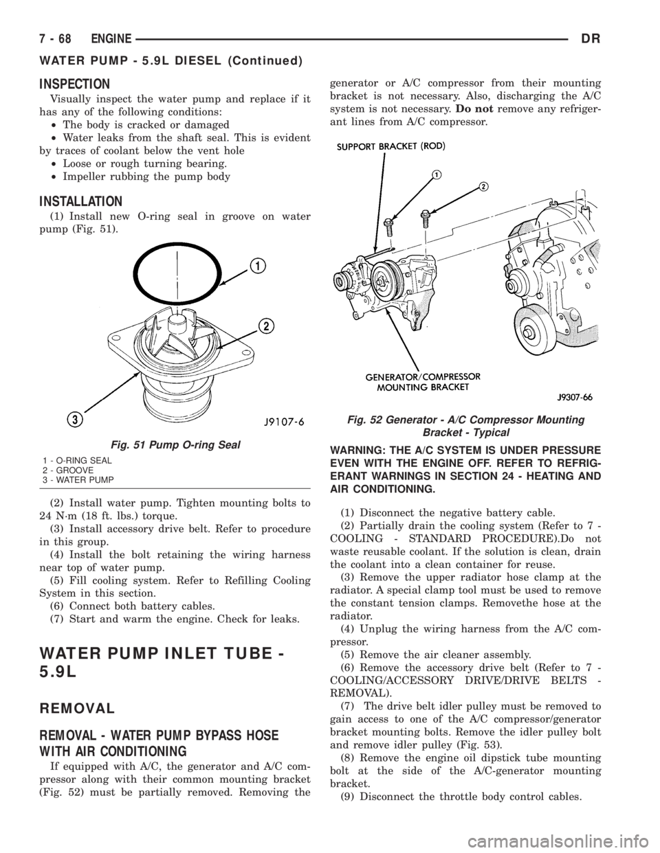
(1) Install new O-ring seal in groove on water
pump (Fig. 51).
(2) Install water pump. Tighten mounting bolts to
24 N´m (18 ft. lbs.) torque.
(3) Install accessory drive belt. Refer to procedure
in this group.
(4) Install the bolt retaining the wiring harness
near top of water pump.
(5) Fill cooling system. Refer to Refilling Cooling
System in this section.
(6) Connect both battery cables.
(7) Start and warm the engine. Check for leaks.
WATER PUMP INLET TUBE -
5.9L
REMOVAL
REMOVAL - WATER PUMP BYPASS HOSE
WITH AIR CONDITIONING
If equipped with A/C, the generator and A/C com-
pressor along with their common mounting bracket
(Fig. 52) must be partially removed. Removing thegenerator or A/C compressor from their mounting
bracket is not necessary. Also, discharging the A/C
system is not necessary.Do notremove any refriger-
ant lines from A/C compressor.
WARNING: THE A/C SYSTEM IS UNDER PRESSURE
EVEN WITH THE ENGINE OFF. REFER TO REFRIG-
ERANT WARNINGS IN SECTION 24 - HEATING AND
AIR CONDITIONING.
(1) Disconnect the negative battery cable.
(2) Partially drain the cooling system (Refer to 7 -
COOLING - STANDARD PROCEDURE).Do not
waste reusable coolant. If the solution is clean, drain
the coolant into a clean container for reuse.
(3) Remove the upper radiator hose clamp at the
radiator. A special clamp tool must be used to remove
the constant tension clamps. Removethe hose at the
radiator.
(4) Unplug the wiring harness from the A/C com-
pressor.
(5) Remove the air cleaner assembly.
(6) Remove the accessory drive belt (Refer to 7 -
COOLING/ACCESSORY DRIVE/DRIVE BELTS -
REMOVAL).
(7) The drive belt idler pulley must be removed to
gain access to one of the A/C compressor/generator
bracket mounting bolts. Remove the idler pulley bolt
and remove idler pulley (Fig. 53).
(8) Remove the engine oil dipstick tube mounting
bolt at the side of the A/C-generator mounting
bracket.
(9) Disconnect the throttle body control cables.
Fig. 51 Pump O-ring Seal
1 - O-RING SEAL
2 - GROOVE
3 - WATER PUMP
Fig. 52 Generator - A/C Compressor Mounting
Bracket - Typical
7 - 68 ENGINEDR
WATER PUMP - 5.9L DIESEL (Continued)
Page 356 of 2895
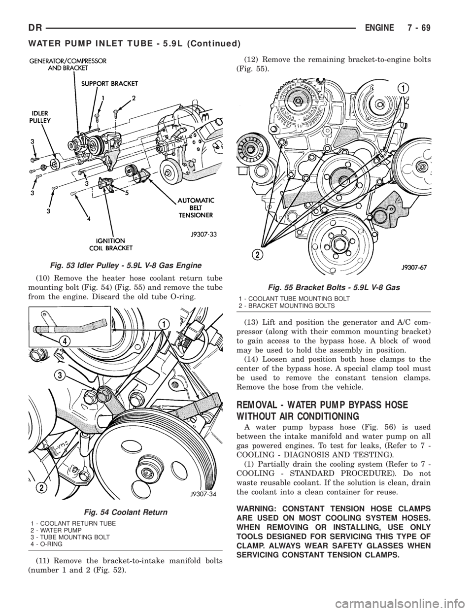
(10) Remove the heater hose coolant return tube
mounting bolt (Fig. 54) (Fig. 55) and remove the tube
from the engine. Discard the old tube O-ring.
(11) Remove the bracket-to-intake manifold bolts
(number 1 and 2 (Fig. 52).(12) Remove the remaining bracket-to-engine bolts
(Fig. 55).
(13) Lift and position the generator and A/C com-
pressor (along with their common mounting bracket)
to gain access to the bypass hose. A block of wood
may be used to hold the assembly in position.
(14) Loosen and position both hose clamps to the
center of the bypass hose. A special clamp tool must
be used to remove the constant tension clamps.
Remove the hose from the vehicle.
REMOVAL - WATER PUMP BYPASS HOSE
WITHOUT AIR CONDITIONING
A water pump bypass hose (Fig. 56) is used
between the intake manifold and water pump on all
gas powered engines. To test for leaks, (Refer to 7 -
COOLING - DIAGNOSIS AND TESTING).
(1) Partially drain the cooling system (Refer to 7 -
COOLING - STANDARD PROCEDURE). Do not
waste reusable coolant. If the solution is clean, drain
the coolant into a clean container for reuse.
WARNING: CONSTANT TENSION HOSE CLAMPS
ARE USED ON MOST COOLING SYSTEM HOSES.
WHEN REMOVING OR INSTALLING, USE ONLY
TOOLS DESIGNED FOR SERVICING THIS TYPE OF
CLAMP. ALWAYS WEAR SAFETY GLASSES WHEN
SERVICING CONSTANT TENSION CLAMPS.
Fig. 53 Idler Pulley - 5.9L V-8 Gas Engine
Fig. 54 Coolant Return
1 - COOLANT RETURN TUBE
2 - WATER PUMP
3 - TUBE MOUNTING BOLT
4 - O-RING
Fig. 55 Bracket Bolts - 5.9L V-8 Gas
1 - COOLANT TUBE MOUNTING BOLT
2 - BRACKET MOUNTING BOLTS
DRENGINE 7 - 69
WATER PUMP INLET TUBE - 5.9L (Continued)
Page 357 of 2895

CAUTION: A number or letter is stamped into the
tongue of the constant tension clamps. If replace-
ment is necessary, use only an original equipment
clamp with a matching number or letter and width.
(2) Loosen both of the bypass hose clamps and
position them to the center of the hose.
(3) Removethe hose from the vehicle.
INSTALLATION
INSTALLATION - WATER PUMP BYPASS HOSE
WITH AIR CONDITIONING
(1) Position the bypass hose clamps to the center
of the bypass hose.
(2) Install the bypass hose to the engine.
(3) Secure both of the hose clamps.
(4) Install the generator-A/C mounting bracket
assembly to the engine. Tighten bolt number 1 (Fig.
53) to 41 N´m (30 ft. lbs.). Tighten bolt number 2
(Fig. 53) to 28 N´m (20 ft. lbs.). Tighten bracket
mounting bolts (Fig. 53) (Fig. 53) to 40 N´m (30 ft.
lbs.).
(5) Install a new O-ring to the heater hose coolant
return tube. Coat the new O-ring with antifreeze
before installation.
(6) Install the coolant return tube and its mount-
ing bolt to the engine.
(7) Connect the throttle body control cables.
(8) Install the oil dipstick mounting bolt.
(9) Install the idler pulley. Tighten the bolt to 41
N´m (30 ft. lbs.) (Fig. 57).
(10) Install the drive belt (Refer to 7 - COOLING/
ACCESSORY DRIVE/DRIVE BELTS - INSTALLA-
TION).CAUTION: When installing the serpentine accessory
drive belt, the belt must be routed correctly. If not,
the engine may overheat due to the water pump
rotating in the wrong direction (Refer to 7 - COOL-
ING/ACCESSORY DRIVE/DRIVE BELTS - INSTALLA-
TION). The correct belt with the correct length must
be used.
(11) Install the air cleaner assembly.
(12) Install the upper radiator hose to the radiator.
(13) Connect the throttle cable to the clip at the
radiator fan shroud.
(14) Connect the wiring harness to the A/C com-
pressor.
(15) Fill the cooling system (Refer to 7 - COOLING
- STANDARD PROCEDURE).
(16) Start and warm the engine. Check for leaks.
INSTALLATION - WATER PUMP BYPASS HOSE
WITHOUT AIR CONDITIONING
(1) Position the bypass hose clamps to the center
of the bypass hose.
(2) Install the bypass hose tothe engine.
(3) Secure both of the hose clamps.
(4) Fill the cooling system (Refer to 7 - COOLING
- STANDARD PROCEDURE).
(5) Start and warm the engine. Check for leaks.
WATER PUMP - 5.7L
REMOVAL
(1) Disconnect negative battery cable.
(2) Drain coolant.
(3) Remove serpentine belt.
(4) Remove fan clutch assembly.
(5) Remove coolant fill bottle.
Fig. 56 Water Pump Bypass Hose - Typical
1 - WATER PUMP BYPASS HOSE
2 - FAN BLADE ASSEMBLY
3 - VISCOUS FAN DRIVE
4 - WATER PUMP AND PULLEY
Fig. 57 Tensioner Mounting
1 - DOWEL PIN HOLE
2 - TENSIONER MOUNTING BRACKET
7 - 70 ENGINEDR
WATER PUMP INLET TUBE - 5.9L (Continued)
Page 358 of 2895
(6) Disconnect washer bottle wiring and hose.
(7) Remove fan shroud assembly.
(8) Remove A/C compressor and genterator brace.
(9) Remove idler pulleys.
(10) Remove belt tensioner assembly.
(11) Remove upper and lower radiator hoses.
(12) Remove heater hoses.
(13) Remove water pump mounting bolts and
remove pump.INSTALLATION
(1) Install water pump and mounting bolts.
Tighten moubting bolts to 24 N´m (18 ft. lbs.).
(2) Install heater hoses.
(3) Install upper and lower radiator hoses.
(4) Install belt tensioner assembly.
(5) Install idler pulleys.
(6) Install A/C compressor and alternator brace.
Tighten bolt and nuts to 28 N´m (21 ft. lbs.).
(7) Install fan shroud assembly.
(8) Connect washer bottle wiring and hose.
(9) Install coolant fill bottle.
(10) Install fan clutch assembly.
(11) Install serpentine belt.
(12) Connect negative battery cable.
(13) Fill coolant.
(14) Pressure test coolant system
DRENGINE 7 - 71
WATER PUMP - 5.7L (Continued)
Page 385 of 2895

ENGINE CONTROL MODULE
DESCRIPTION - ECM
The Engine Control Module (ECM) is bolted to the
left side of the engine below the intake manifold (Fig.
2).
OPERATION - ECM
The main function of the Engine Control Module
(ECM) is to electrically control the fuel system. The
Powertrain Control Module (PCM)does not control
the fuel system.
The ECM can adapt its programming to meet
changing operating conditions.If the ECM has
been replaced, flashed or re-calibrated, the
ECM must learn the Accelerator Pedal Position
Sensor (APPS) idle voltage. Failure to learn
this voltage may result in unnecessary diagnos-
tic trouble codes. Refer to ECM Removal/Instal-
lation for learning procedures.
The ECM receives input signals from various
switches and sensors. Based on these inputs, the
ECM regulates various engine and vehicle operations
through different system components. These compo-
nents are referred to asECM Outputs.The sensors
and switches that provide inputs to the ECM are
consideredECM Inputs.NOTE: ECM Inputs:
²Accelerator Pedal Position Sensor (APPS) Volts
²APPS1 Signal Ð For off engine APPS
²APPS2 Signal Ð For off engine APPS
²APPS Idle Validation Switches #1 and #2
²Battery voltage
²Camshaft Position Sensor (CMP)
²CCD bus (+) circuits
²CCD bus (-) circuits
²Crankshaft Position Sensor (CKP)
²Data link connection for DRB scan tool
²Engine Coolant Temperature (ECT) sensor
²Ground circuits
²Fuel Pressure Sensor
²Battery Temperature
²Fan speed
²Inlet Air Temperature Sensor/Pressure Sensor
²Intake Air Temperature Sensor/MAP Sensor
²Oil Pressure SWITCH
²Power ground
²Sensor return
²Signal ground
²Water-In-Fuel (WIF) sensor
NOTE: ECM Outputs:
After inputs are received by the ECM, certain sen-
sors, switches and components are controlled or reg-
ulated by the ECM. These are consideredECM
Outputs.These outputs are for:
²CCD bus (+) circuits
²CCD bus (-) circuits
²CKP and APPS outputs to the PCM
²Data link connection for DRB scan tool
²Five volt sensor supply
²Fuel transfer (lift) pump
²Intake manifold air heater relays #1 and #2 con-
trol circuits
²Malfunction indicator lamp (Check engine lamp)
(databus)
²Oil Pressure Swith/warning lamp (databus)
²Fuel Control Actuator
²Wait-to-start warning lamp (databus)
²Fan Clutch PWM
²Water-In-Fuel (WIF) warning lamp (databus)
REMOVAL
The Engine Control Module (ECM) is bolted to a
support bracket near the fuel filter. The support
bracket mounts to the block with four capscrews and
vibration isolators. A ground wire is fastened to the
bracket. The other end of the wire is fastened to the
engine block.
(1) Record any Diagnostic Trouble Codes (DTC's)
found in the ECM.
Fig. 2 DIESEL ECM
1 - ENGINE CONTROL MODULE (ECM)
2 - ECM MOUNTING BOLT
3 - 50-WAY CONNECTOR
4 - SUPPORT PLATE
5 - 60-WAY CONNECTOR
8E - 4 ELECTRONIC CONTROL MODULESDR
Page 430 of 2895
(8) Remove generator from vehicle.
INSTALLATION
3.7L / 4.7L
(1) Position generator to engine and install 2 hor-
izontal bolts and 1 vertical bolt.
(2) Tighten all 3 bolts. Refer to Torque Specifica-
tions.
(3) Snap field wire connector into rear of genera-
tor.
(4) Install B+ terminal eyelet to generator output
stud. Tighten mounting nut. Refer to Torque Specifi-
cations.
CAUTION: Never force a belt over a pulley rim
using a screwdriver. The synthetic fiber of the belt
can be damaged.
CAUTION: When installing a serpentine accessory
drive belt, the belt MUST be routed correctly. The
water pump may be rotating in the wrong direction
if the belt is installed incorrectly, causing the
engine to overheat. Refer to belt routing label in
engine compartment, or refer to Belt Schematics in
7, Cooling System.
(5) Install generator drive belt. Refer to 7, Cooling
System for procedure.
(6) Install negative battery cable to battery.
5.7L
(1) Position generator to engine and install 2
mounting bolts.
(2) Tighten bolts. Refer to Torque Specifications.
(3) Position support bracket to front of generator
and install bolt and nuts. Tighten bolt / nuts. Refer
to Torque Specifications.
(4) Snap field wire connector into rear of genera-
tor.
(5) Install B+ terminal eyelet to generator output
stud. Tighten mounting nut. Refer to Torque Specifi-
cations.
CAUTION: Never force a belt over a pulley rim
using a screwdriver. The synthetic fiber of the belt
can be damaged.
CAUTION: When installing a serpentine accessory
drive belt, the belt MUST be routed correctly. The
water pump may be rotating in the wrong direction
if the belt is installed incorrectly, causing the
engine to overheat. Refer to belt routing label in
engine compartment, or refer to Belt Schematics in
7, Cooling System.
(6) Install generator drive belt. Refer to 7, Cooling
System for procedure.
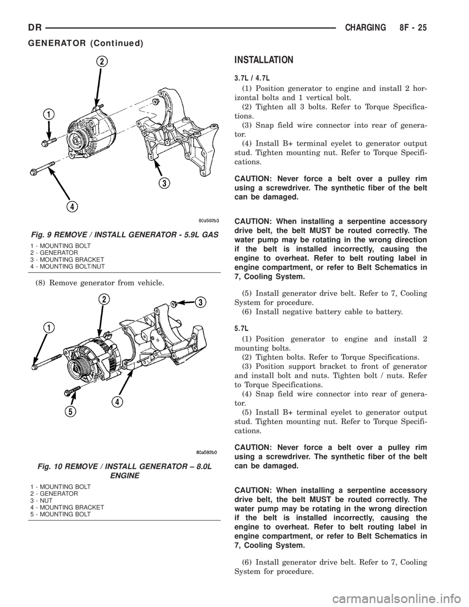
Fig. 9 REMOVE / INSTALL GENERATOR - 5.9L GAS
1 - MOUNTING BOLT
2 - GENERATOR
3 - MOUNTING BRACKET
4 - MOUNTING BOLT/NUT
Fig. 10 REMOVE / INSTALL GENERATOR ± 8.0L
ENGINE
1 - MOUNTING BOLT
2 - GENERATOR
3 - NUT
4 - MOUNTING BRACKET
5 - MOUNTING BOLT
DRCHARGING 8F - 25
GENERATOR (Continued)