2003 DODGE RAM water pump
[x] Cancel search: water pumpPage 431 of 2895
(7) Install negative battery cable to battery.
5.9L Diesel
(1) Position generator to upper and lower mount-
ing brackets and install upper bolt and lower bolt /
nut.
(2) Tighten all bolts / nut. Refer to Torque Specifi-
cations.
(3) Snap field wire connector into rear of genera-
tor.
(4) Install B+ terminal eyelet to generator output
stud. Tighten mounting nut. Refer to Torque Specifi-
cations.
CAUTION: Never force a belt over a pulley rim
using a screwdriver. The synthetic fiber of the belt
can be damaged.
CAUTION: When installing a serpentine accessory
drive belt, the belt MUST be routed correctly. The
water pump may be rotating in the wrong direction
if the belt is installed incorrectly, causing the
engine to overheat. Refer to belt routing label in
engine compartment, or refer to Belt Schematics in
7, Cooling System.
(5) Install generator drive belt. Refer to 7, Cooling
System for procedure.
(6) Install both negative battery cables to both bat-
teries.
8.0L
(1) Position generator to engine and install lower
bolt and upper bolt / nut.
(2) Tighten all bolts / nut. Refer to Torque Specifi-
cations.
(3) Snap field wire connector into rear of genera-
tor.
(4) Install B+ terminal eyelet to generator output
stud. Tighten mounting nut. Refer to Torque Specifi-
cations.
CAUTION: Never force a belt over a pulley rim
using a screwdriver. The synthetic fiber of the belt
can be damaged.CAUTION: When installing a serpentine accessory
drive belt, the belt MUST be routed correctly. The
water pump may be rotating in the wrong direction
if the belt is installed incorrectly, causing the
engine to overheat. Refer to belt routing label in
engine compartment, or refer to Belt Schematics in
7, Cooling System.
(5) Install generator drive belt. Refer to 7, Cooling
System for procedure.
(6) Install negative battery cable to battery.
5.9L Gas
(1) Position generator to engine and install upper
bolt and lower bolt / nut.
(2) Tighten all bolts / nut. Refer to Torque Specifi-
cations.
(3) Snap field wire connector into rear of genera-
tor.
(4) Install B+ terminal eyelet to generator output
stud. Tighten mounting nut. Refer to Torque Specifi-
cations.
CAUTION: Never force a belt over a pulley rim
using a screwdriver. The synthetic fiber of the belt
can be damaged.
CAUTION: When installing a serpentine accessory
drive belt, the belt MUST be routed correctly. The
water pump may be rotating in the wrong direction
if the belt is installed incorrectly, causing the
engine to overheat. Refer to belt routing label in
engine compartment, or refer to Belt Schematics in
7, Cooling System.
(5) Install generator drive belt. Refer to 7, Cooling
System for procedure.
(6) Install negative battery cable to battery.
8F - 26 CHARGINGDR
GENERATOR (Continued)
Page 681 of 2895
If the control knob is held depressed for more than
about thirty seconds, the FCM will suspend washer
pump/motor operation until the knob is released for
about two seconds, then cycled back to the Wash
position; however, the wipers will continue to operate
for as long as the Wash switch is held closed. The
FCM monitors the changing state of the wiper motor
park switch through a hard wired wiper park switch
sense circuit input. This input allows the FCM to
count the number of wipe cycles that occur after the
Wash switch is released, and to determine the proper
interval at which to de-energize the wiper on/off
relay to complete the wipe-after-wash mode cycle.
DIAGNOSIS AND TESTING - WIPER &
WASHER SYSTEM
If the wiper motor operates, but the wipers do not
move on the windshield, replace the faulty wiper
module. If the washer pump/motor operates, but no
washer fluid is dispensed on the glass; or, if the wip-
ers operate, but chatter, lift, or do not clear the glass,
clean and inspect the wiper and washer system com-
ponents as required. (Refer to 8 - ELECTRICAL/
WIPERS/WASHERS - CLEANING) and (Refer to 8 -
ELECTRICAL/WIPERS/WASHERS - INSPECTION).
For diagnosis and testing of the multi-function
switch (Refer to 8 - ELECTRICAL/LAMPS/LIGHT-
ING - EXTERIOR/MULTI-FUNCTION SWITCH -
DIAGNOSIS AND TESTING). Refer to the appropri-
ate wiring information. The wiring information
includes wiring diagrams, proper wire and connector
repair procedures, details of wire harness routing
and retention, connector pin-out information and
location views for the various wire harness connec-
tors, splices and grounds.
The hard wired circuits and components of the
wiper and washer system may be diagnosed and
tested using conventional diagnostic tools and proce-
dures. However, conventional diagnostic methods
may not prove conclusive in the diagnosis of the
instrument cluster, the Front Control Module (FCM),
or the electronic message inputs to or outputs from
the instrument cluster and the FCM that control the
various wiper and washer system operating modes.
The most reliable, efficient, and accurate means to
diagnose the instrument cluster, the FCM, or the
electronic message inputs and outputs related to the
various wiper and washer system operating modes
requires the use of a DRBIIItscan tool. Refer to the
appropriate diagnostic information.
WARNING: ON VEHICLES EQUIPPED WITH AIR-
BAGS, DISABLE THE SUPPLEMENTAL RESTRAINT
SYSTEM BEFORE ATTEMPTING ANY STEERING
WHEEL, STEERING COLUMN, DRIVER AIRBAG,
PASSENGER AIRBAG, SEAT BELT TENSIONER,SIDE CURTAIN AIRBAG, OR INSTRUMENT PANEL
COMPONENT DIAGNOSIS OR SERVICE. DISCON-
NECT AND ISOLATE THE BATTERY NEGATIVE
(GROUND) CABLE, THEN WAIT TWO MINUTES FOR
THE SYSTEM CAPACITOR TO DISCHARGE BEFORE
PERFORMING FURTHER DIAGNOSIS OR SERVICE.
THIS IS THE ONLY SURE WAY TO DISABLE THE
SUPPLEMENTAL RESTRAINT SYSTEM. FAILURE TO
TAKE THE PROPER PRECAUTIONS COULD
RESULT IN ACCIDENTAL AIRBAG DEPLOYMENT
AND POSSIBLE PERSONAL INJURY.
CLEANING - WIPER & WASHER SYSTEM
WIPER SYSTEM
The squeegees of wiper blades exposed to the ele-
ments for a long time tend to lose their wiping effec-
tiveness. Periodic cleaning of the squeegees is
suggested to remove any deposits of salt or road film.
The wiper blades, arms, and windshield glass should
only be cleaned using a sponge or soft cloth and
windshield washer fluid, a mild detergent, or a non-
abrasive cleaner. If the wiper blades continue to
leave streaks, smears, hazing, or beading on the
glass after thorough cleaning of the squeegees and
the glass, the entire wiper blade assembly must be
replaced.
CAUTION: Protect the rubber squeegees of the
wiper blades from any petroleum-based cleaners,
solvents, or contaminants. These products can rap-
idly deteriorate the rubber squeegees.
WASHER SYSTEM
If the washer system is contaminated with foreign
material, drain the washer reservoir by removing the
washer pump/motor from the reservoir. Clean foreign
material from the inside of the washer pump/motor
inlet filter screen and the washer reservoir using
clean washer fluid, a mild detergent, or a non-abra-
sive cleaner. Flush foreign material from the washer
system plumbing by first disconnecting the washer
hoses from the washer nozzles, then running the
washer pump/motor to run clean washer fluid or
water through the system. Plugged or restricted
washer nozzles should be carefully back-flushed
using compressed air. If the washer nozzle obstruc-
tion cannot be cleared, replace the washer nozzle.
CAUTION: Never introduce petroleum-based clean-
ers, solvents, or contaminants into the washer sys-
tem. These products can rapidly deteriorate the
rubber seals and hoses of the washer system, as
well as the rubber squeegees of the wiper blades.
8R - 6 WIPERS/WASHERSDR
WIPERS/WASHERS (Continued)
Page 683 of 2895
CHECK VALVE
DESCRIPTION
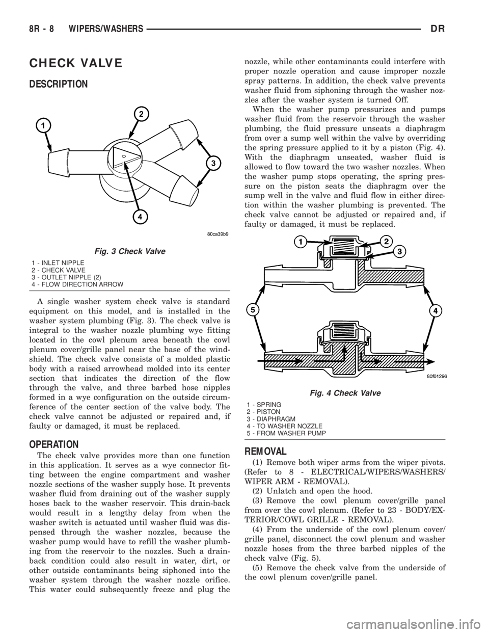
A single washer system check valve is standard
equipment on this model, and is installed in the
washer system plumbing (Fig. 3). The check valve is
integral to the washer nozzle plumbing wye fitting
located in the cowl plenum area beneath the cowl
plenum cover/grille panel near the base of the wind-
shield. The check valve consists of a molded plastic
body with a raised arrowhead molded into its center
section that indicates the direction of the flow
through the valve, and three barbed hose nipples
formed in a wye configuration on the outside circum-
ference of the center section of the valve body. The
check valve cannot be adjusted or repaired and, if
faulty or damaged, it must be replaced.
OPERATION
The check valve provides more than one function
in this application. It serves as a wye connector fit-
ting between the engine compartment and washer
nozzle sections of the washer supply hose. It prevents
washer fluid from draining out of the washer supply
hoses back to the washer reservoir. This drain-back
would result in a lengthy delay from when the
washer switch is actuated until washer fluid was dis-
pensed through the washer nozzles, because the
washer pump would have to refill the washer plumb-
ing from the reservoir to the nozzles. Such a drain-
back condition could also result in water, dirt, or
other outside contaminants being siphoned into the
washer system through the washer nozzle orifice.
This water could subsequently freeze and plug thenozzle, while other contaminants could interfere with
proper nozzle operation and cause improper nozzle
spray patterns. In addition, the check valve prevents
washer fluid from siphoning through the washer noz-
zles after the washer system is turned Off.
When the washer pump pressurizes and pumps
washer fluid from the reservoir through the washer
plumbing, the fluid pressure unseats a diaphragm
from over a sump well within the valve by overriding
the spring pressure applied to it by a piston (Fig. 4).
With the diaphragm unseated, washer fluid is
allowed to flow toward the two washer nozzles. When
the washer pump stops operating, the spring pres-
sure on the piston seats the diaphragm over the
sump well in the valve and fluid flow in either direc-
tion within the washer plumbing is prevented. The
check valve cannot be adjusted or repaired and, if
faulty or damaged, it must be replaced.REMOVAL
(1) Remove both wiper arms from the wiper pivots.
(Refer to 8 - ELECTRICAL/WIPERS/WASHERS/
WIPER ARM - REMOVAL).
(2) Unlatch and open the hood.
(3) Remove the cowl plenum cover/grille panel
from over the cowl plenum. (Refer to 23 - BODY/EX-
TERIOR/COWL GRILLE - REMOVAL).
(4) From the underside of the cowl plenum cover/
grille panel, disconnect the cowl plenum and washer
nozzle hoses from the three barbed nipples of the
check valve (Fig. 5).
(5) Remove the check valve from the underside of
the cowl plenum cover/grille panel.
Fig. 3 Check Valve
1 - INLET NIPPLE
2 - CHECK VALVE
3 - OUTLET NIPPLE (2)
4 - FLOW DIRECTION ARROW
Fig. 4 Check Valve
1 - SPRING
2 - PISTON
3 - DIAPHRAGM
4 - TO WASHER NOZZLE
5 - FROM WASHER PUMP
8R - 8 WIPERS/WASHERSDR
Page 721 of 2895

Component Page
Overdrive Switch...................... 8W-31
Overhead Map/Reading Lamp............ 8W-44
Oxygen Sensors....................... 8W-30
Oxygen Sensor Downstream Relay........ 8W-30
Park Brake Switch.................... 8W-40
Park Lamp Relay................... 8W-50, 52
Park/Turn Signal Lamps............. 8W-50, 52
Passenger Airbag On/Off Switch.......... 8W-43
Blend Door Actuators.................. 8W-42
Passenger Lumbar Switch............... 8W-63
Power Mirrors........................ 8W-62
Power Outlet......................... 8W-41
Power Outlet-Console.................. 8W-41
Power Seat Motors.................... 8W-63
Power Seat Switches................... 8W-63
Power Steering Pressure Switch.......... 8W-30
Power Window Circuit Breaker........... 8W-10
Power Window Motors.................. 8W-60
Power Window Switches................ 8W-60
Powertrain Control Module.............. 8W-30
PTCs............................... 8W-10
PTO Switch.......................... 8W-30
Radio............................... 8W-47
Recirculation Door Actuator............. 8W-42
Red Brake Warning Indicator Switch . . . 8W-34, 35
Remote Radio Switches................. 8W-47
Splices.............................. 8W-70
Seat Belt Pretensioners................. 8W-43
Seat Belt Switch-Driver................ 8W-40
Seat Belt Tensioner Reducer............. 8W-40
Seat Heater Interface Module............ 8W-63
Sentry Key Immobilizer Module.......... 8W-39
Spare Relay.......................... 8W-10
Speakers............................ 8W-47Component Page
Speed Control Servo................... 8W-33
Speed Control Switches................. 8W-33
Starter Motor Relay................... 8W-21
Starter Motor.................... 8W-21, 21-3
Tail/Stop Lamps...................... 8W-52
Tail/Stop/Turn Signal Lamps.......... 8W-51, 52
Tail/Turn Lamps...................... 8W-52
Tailgate Lamp Assembly................ 8W-51
Throttle Position Sensor................ 8W-30
Throttle Position Switch................ 8W-30
Trailer Tow Connector.................. 8W-54
Trailer Tow Connector-Add On........... 8W-54
Trailer Tow Left Turn Relay............. 8W-54
Trailer Tow Right Turn Relay............ 8W-54
Transfer Case Control Module............ 8W-31
Transfer Case Mode Sensor.............. 8W-31
Transfer Case Selector Switch............ 8W-31
Transfer Case Shift Motor............... 8W-31
Transmission Control Module............ 8W-31
Transmission Control Relay............. 8W-31
Transmission Range Sensor.............. 8W-31
Transmission Solenoid Assembly.......... 8W-31
Transmission Solenoid/TRS Assembly...... 8W-31
Underhood Lamp...................... 8W-44
Vacuum Pump........................ 8W-30
Vehicle Speed Sensor................... 8W-30
Vistronic Fan Drive.................... 8W-30
Washer Fluid Level Switch.............. 8W-53
Washer Pump Motor-Front.............. 8W-53
Water In Fuel Sensor.................. 8W-30
Wheel Speed Sensors................... 8W-35
Wiper High/Low Relay................. 8W-53
Wiper Motor-Front.................... 8W-53
8W - 02 - 2 8W-02 COMPONENT INDEXDR
Page 816 of 2895

8W-30 FUEL/IGNITION SYSTEM
Component PageA/C Compressor Clutch Relay...........8W-30-27, 36, 83
A/C Pressure Transducer.......8W-30-19, 20, 21, 48, 53, 70
Accelerator Pedal Position Sensor.............8W-30-55
Adjustable Pedal Motor....................8W-30-87
Adjustable Pedal Relay....................8W-30-87
Adjustable Pedal Switch...................8W-30-87
Ambient Temperature Sensor................8W-30-56
Auto Shut Down Relay..................8W-30-4, 31
Battery..............................8W-30-77
Battery Temperature Sensor............8W-30-28, 39, 81
Brake Lamp Switch.............8W-30-25, 35, 65, 82, 89
Camshaft Position Sensor.......8W-30-17, 18, 37, 55, 70, 71
Capacitor.........................8W-30-6, 11, 43
Clockspring..................8W-30-25, 35, 65, 84, 90
Clutch Interlock Brake Switch...............8W-30-32
Coil On Plug No. 1...................8W-30-8, 42, 61
Coil On Plug No. 2...................8W-30-7, 40, 60
Coil On Plug No. 3...................8W-30-8, 42, 61
Coil On Plug No. 4...................8W-30-7, 40, 60
Coil On Plug No. 5...................8W-30-6, 41, 61
Coil On Plug No. 6...................8W-30-6, 43, 60
Coil On Plug No. 7....................8W-30-41, 61
Coil On Plug No. 8....................8W-30-43, 60
Condenser Fan Relay...................8W-30-27, 36
Controller Antilock Brake...........8W-30-23, 33, 38, 82
Crankshaft Position Sensor.............8W-30-17, 18, 37
Data Link Connector..........8W-30-27, 36, 46, 80, 89, 91
Data Link Connector-Engine................8W-30-75
Electronic Throttle Control Module............8W-30-63
Engine Control Module......8W-30-67, 68, 69, 70, 71, 72, 73,
74, 75, 76, 77, 78, 79, 80, 81, 82,
83, 84, 90, 91
Engine Coolant Temperature
Sensor.................8W-30-19, 20, 21, 48, 64, 72
Engine Oil Pressure Switch......8W-30-19, 20, 21, 29, 78, 81
EVAP/Purge Solenoid...................8W-30-28, 39
Front Control Module.....................8W-30-87
Fuel Heater...........................8W-30-85
Fuel Heater Relay.......................8W-30-85
Fuel Injector No. 1...............8W-30-8, 9, 11, 42, 62
Fuel Injector No. 2...............8W-30-7, 9, 12, 40, 59
Fuel Injector No. 3...............8W-30-8, 9, 11, 42, 62
Fuel Injector No. 4...............8W-30-7, 9, 12, 40, 60
Fuel Injector No. 5...............8W-30-6, 9, 11, 41, 62
Fuel Injector No. 6...............8W-30-6, 9, 12, 43, 59
Fuel Injector No. 7................8W-30-9, 11, 41, 62
Fuel Injector No. 8................8W-30-9, 12, 43, 59
Fuel Injector No. 9.......................8W-30-11
Fuel Injector No. 10......................8W-30-12
Fuel Injector Pack No. 1...................8W-30-67
Fuel Injector Pack No. 2..............8W-30-67, 68, 69
Fuel Injector Pack No. 3...................8W-30-69
Fuel Pump Module................8W-30-3, 30, 79, 83
Fuel Pump Motor.......................8W-30-76
Fuel Pump Relay......................8W-30-3, 30
Fuel Rail Pressure Sensor..................8W-30-74
Fuse 2.............................8W-30-4, 31
Fuse 5............................8W-30-50, 88
Fuse 12.............................8W-30-85
Fuse 17............................8W-30-3, 30
Fuse 19.......................8W-30-2, 29, 77, 90
Fuse 36...........................8W-30-79, 87
Fuse 40.............................8W-30-87
Fuse 49............................8W-30-4, 31
Fuse 50...........................8W-30-28, 88Component PageFusible Link..........................8W-30-77
G103.........................8W-30-3, 25, 30, 35
G104.........................8W-30-3, 25, 30, 35
G105.............................8W-30-81, 86
G106...............................8W-30-85
G107.........8W-30-2, 16, 24, 29, 34, 40, 42, 45, 47, 50, 54
G114 ...............................8W-30-78
G117 ...............................8W-30-91
G120.............................8W-30-75, 85
G201..........................8W-30-23, 33, 91
G203...............................8W-30-87
Generator.......................8W-30-24, 34, 75
Idle Air Control Motor..................8W-30-27, 36
Ignition Coil...........................8W-30-9
Ignition Coil-Left.......................8W-30-10
Ignition Coil-Right.......................8W-30-10
Ignition Switch....................8W-30-23, 33, 46
Inlet Air Temperature/Pressure Sensor..........8W-30-73
Input Speed Sensor......................8W-30-49
Intake Air Heater Relay No. 1...............8W-30-81
Intake Air Heater Relay No. 2...............8W-30-81
Intake Air Temperature Sensor......8W-30-19, 20, 21, 48, 64
Intake Air Temperature/Manifold Absolute Pressure
Sensor............................8W-30-74
Integrated Power Module . . 8W-30-2, 3, 4, 26, 27, 29, 30, 31, 36,
50, 77, 79, 80, 83, 85, 86, 87, 88, 90
Knock Sensor..........................8W-30-22
Knock Sensor-Left.......................8W-30-57
Knock Sensor-Right......................8W-30-57
Leak Detection Pump..................8W-30-24, 34
Lift Pump Motor........................8W-30-75
Line Pressure Sensor.....................8W-30-44
Manifold Absolute Pressure
Sensor.................8W-30-19, 20, 21, 48, 55, 64
Output Speed Sensor................8W-30-26, 49, 88
Overdrive Switch...................8W-30-23, 33, 91
Oxygen Sensor 1/1 Upstream.......8W-30-13, 14, 15, 47, 54
Oxygen Sensor 1/2 Downstream.....8W-30-13, 14, 16, 45, 54
Oxygen Sensor 2/1 Upstream..............8W-30-15, 47
Oxygen Sensor 2/2 Downstream............8W-30-16, 45
Oxygen Sensor Downstream Relay...........8W-30-4, 31
Power Steering Pressure Switch............8W-30-24, 34
Powertrain Control Module . . 8W-30-2, 3, 4, 5, 6, 7, 8, 9, 10, 11,
12, 13, 14, 15, 16 17, 18, 19, 20, 21, 22, 23, 24, 25, 27, 28, 29,
30, 31, 32, 33, 34, 35, 36, 37, 38, 39, 40, 41, 42, 43, 44, 45, 46,
47, 48, 49, 50, 51, 52, 53, 54, 55, 56, 57, 58, 59, 60, 61, 62, 63,
64, 65, 66, 77, 79, 82, 84, 85, 88, 89, 90, 91
PTCNo.1 ...........8W-30-2, 3, 27, 29, 30, 36, 80, 83, 86
PTO Switch.........................8W-30-23, 33
Speed Control Servo.................8W-30-25, 35, 89
Speed Control Switch-Left.............8W-30-65, 84, 90
Speed Control Switch-Right............8W-30-65, 84, 90
Starter Motor Relay......................8W-30-29
Throttle Position Sensor.................8W-30-22, 44
Throttle Position Switch...................8W-30-72
Transfer Case Control Module...............8W-30-65
Transmission Control Module.......8W-30-17, 23, 33, 38, 66
Transmission Control Relay............8W-30-26, 50, 88
Transmission Range Sensor..................8W-30-5
Transmission Solenoid Assembly.......8W-30-20, 21, 26, 88
Transmission Solenoid/TRS Assembly . . 8W-30-5, 32, 50, 51, 52
Vacuum Pump.........................8W-30-86
Vehicle Speed Sensor.....................8W-30-71
Vistronic Fan Drive......................8W-30-79
Water In Fuel Sensor...................8W-30-72, 76
DR8W-30 FUEL/IGNITION SYSTEM 8W - 30 - 1
Page 1071 of 2895
Component Page
Speaker-Right Instrument Panel....... 8W-80-97
Speaker-Right Rear................. 8W-80-97
Speed Control Servo................. 8W-80-97
Speed Control Switch-Left (ETC)....... 8W-80-98
Speed Control Switch-Left (Except ETC) . 8W-80-98
Speed Control Switch-Right (ETC)...... 8W-80-98
Speed Control Switch-Right (Except
ETC)........................... 8W-80-98
Switch-Driver Seat Belt.............. 8W-80-98
Switch-Passenger Airbag On-Off....... 8W-80-99
Tail/Stop/Turn Signal Lamp-Left....... 8W-80-99
Tail/Stop/Turn Signal Lamp-Right...... 8W-80-99
Tension Reducer-Seat Belt (Standard
Cab)........................... 8W-80-99
Tensioner-Left Seat Belt............. 8W-80-100
Tensioner-Right Seat Belt............ 8W-80-100
Throttle Position Sensor............. 8W-80-100
Throttle Position Sensor (Diesel)...... 8W-80-100
Trailer Tow Connector.............. 8W-80-101
Trailer Tow Connector-Add On........ 8W-80-101
Transfer Case Control Module C1...... 8W-80-101
Transfer Case Control Module C2...... 8W-80-102
Transfer Case Control Module C3...... 8W-80-102
Transfer Case Mode Sensor.......... 8W-80-102
Transfer Case Position Sensor (4.7L/
5.9L).......................... 8W-80-103
Transfer Case Selector Switch........ 8W-80-103
Transfer Case Shift Motor........... 8W-80-103
Transmission Control Module......... 8W-80-104Component Page
Transmission Range Sensor (5.9L/
Diesel)........................ 8W-80-105
Transmission Solenoid Assembly (5.9L/
8.0L).......................... 8W-80-105
Transmission Solenoid/Trs Assembly
(3.7L/4.7L/5.7L)................. 8W-80-106
Underhood Lamp.................. 8W-80-106
Vacuum Pump (Diesel).............. 8W-80-106
Vehicle Speed Sensor (Diesel)......... 8W-80-107
Vistronic Fan Drive (Diesel).......... 8W-80-107
Washer Fluid Level Switch........... 8W-80-107
Washer Pump Motor-Front........... 8W-80-107
Water In Fuel Sensor (Diesel)......... 8W-80-107
Wheel Speed Sensor-Left Front
(ABS)......................... 8W-80-108
Wheel Speed Sensor-Rear (ABS)....... 8W-80-108
Wheel Speed Sensor-Right Front
(ABS)......................... 8W-80-108
Wiper Motor-Front................. 8W-80-108
Washer Fluid Level Switch........... 8W-80-109
Washer Pump Motor-Front........... 8W-80-109
Water In Fuel Sensor (Diesel)......... 8W-80-109
Wheel Speed Sensor-Left Front
(ABS)......................... 8W-80-109
Wheel Speed Sensor-Rear (ABS)....... 8W-80-110
Wheel Speed Sensor-Right Front
(ABS)......................... 8W-80-110
Wiper Motor-Front................. 8W-80-110
8W - 80 - 4 8W-80 CONNECTOR PIN-OUTSDR
Page 1174 of 2895
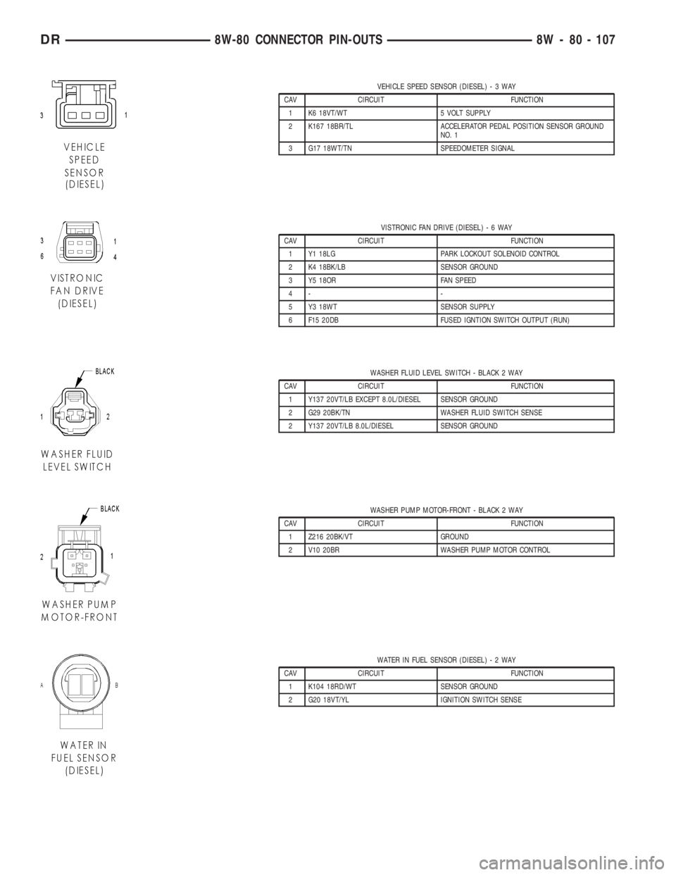
VEHICLE SPEED SENSOR (DIESEL)-3WAY
CAV CIRCUIT FUNCTION
1 K6 18VT/WT 5 VOLT SUPPLY
2 K167 18BR/TL ACCELERATOR PEDAL POSITION SENSOR GROUND
NO. 1
3 G17 18WT/TN SPEEDOMETER SIGNAL
VISTRONIC FAN DRIVE (DIESEL)-6WAY
CAV CIRCUIT FUNCTION
1 Y1 18LG PARK LOCKOUT SOLENOID CONTROL
2 K4 18BK/LB SENSOR GROUND
3 Y5 18OR FAN SPEED
4- -
5 Y3 18WT SENSOR SUPPLY
6 F15 20DB FUSED IGNTION SWITCH OUTPUT (RUN)
WASHER FLUID LEVEL SWITCH - BLACK 2 WAY
CAV CIRCUIT FUNCTION
1 Y137 20VT/LB EXCEPT 8.0L/DIESEL SENSOR GROUND
2 G29 20BK/TN WASHER FLUID SWITCH SENSE
2 Y137 20VT/LB 8.0L/DIESEL SENSOR GROUND
WASHER PUMP MOTOR-FRONT - BLACK 2 WAY
CAV CIRCUIT FUNCTION
1 Z216 20BK/VT GROUND
2 V10 20BR WASHER PUMP MOTOR CONTROL
WATER IN FUEL SENSOR (DIESEL)-2WAY
CAV CIRCUIT FUNCTION
1 K104 18RD/WT SENSOR GROUND
2 G20 18VT/YL IGNITION SWITCH SENSE
DR8W-80 CONNECTOR PIN-OUTS 8W - 80 - 107
Page 1176 of 2895
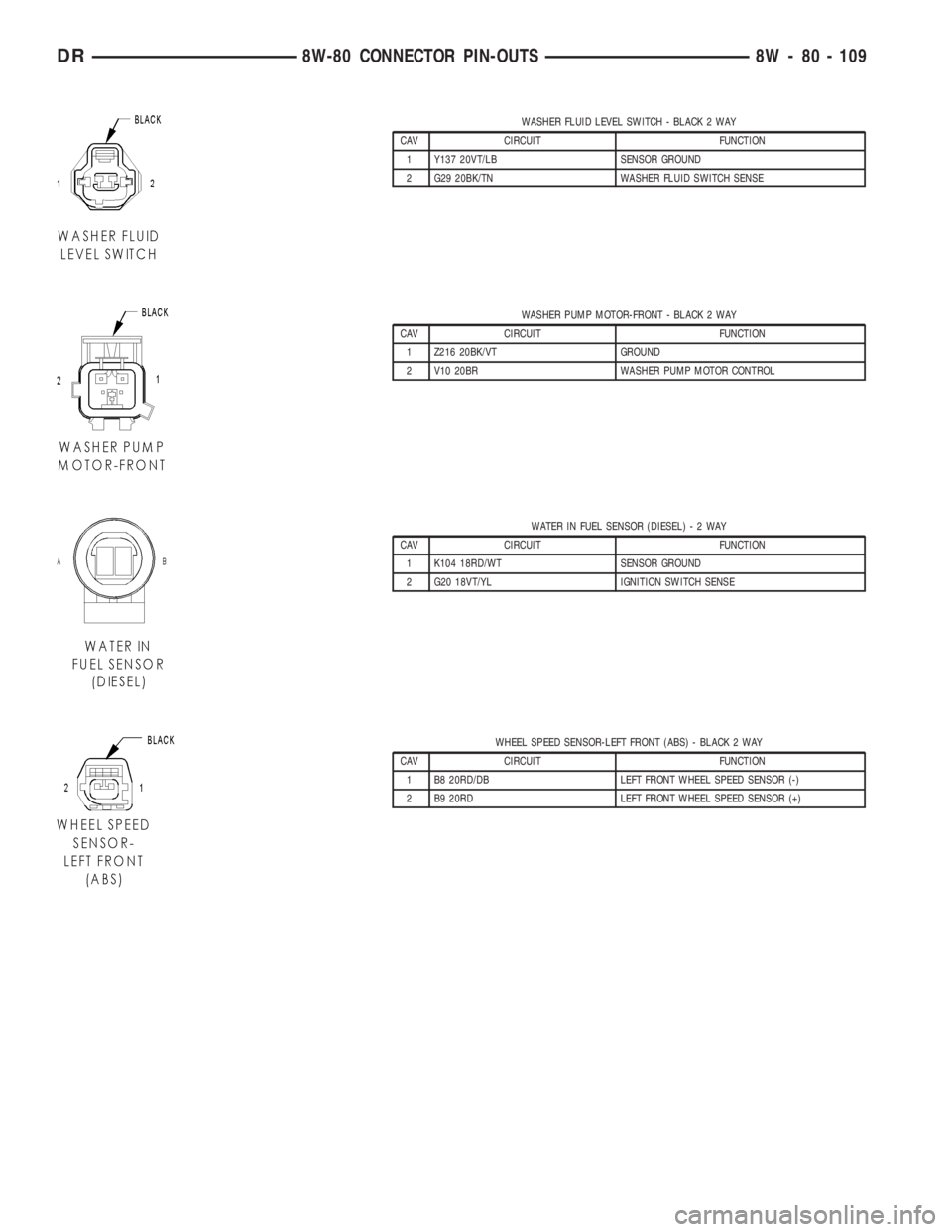
WASHER FLUID LEVEL SWITCH - BLACK 2 WAY
CAV CIRCUIT FUNCTION
1 Y137 20VT/LB SENSOR GROUND
2 G29 20BK/TN WASHER FLUID SWITCH SENSE
WASHER PUMP MOTOR-FRONT - BLACK 2 WAY
CAV CIRCUIT FUNCTION
1 Z216 20BK/VT GROUND
2 V10 20BR WASHER PUMP MOTOR CONTROL
WATER IN FUEL SENSOR (DIESEL)-2WAY
CAV CIRCUIT FUNCTION
1 K104 18RD/WT SENSOR GROUND
2 G20 18VT/YL IGNITION SWITCH SENSE
WHEEL SPEED SENSOR-LEFT FRONT (ABS) - BLACK 2 WAY
CAV CIRCUIT FUNCTION
1 B8 20RD/DB LEFT FRONT WHEEL SPEED SENSOR (-)
2 B9 20RD LEFT FRONT WHEEL SPEED SENSOR (+)
DR8W-80 CONNECTOR PIN-OUTS 8W - 80 - 109