Page 780 of 1690
No.1 Fuel Pipe
Fuel Tube Connector
SST
(Clip)
SST (T joint)SST
SST
(Hose)
B12975
11±34
± FUELFUEL SYSTEM (1AZ±FSE)
AVENSIS REPAIR MANUAL (RM1018E)
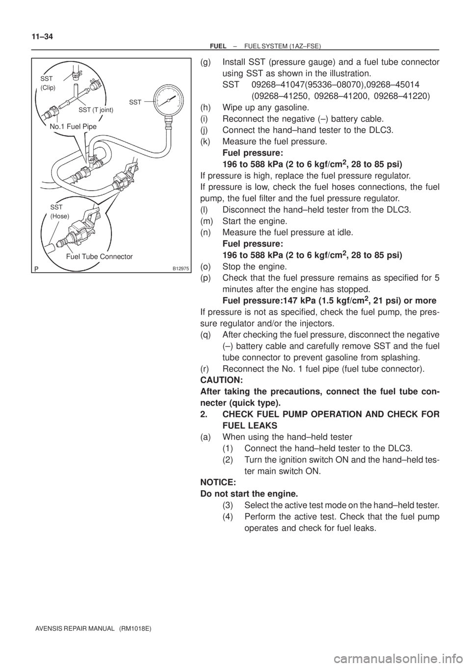
(g) Install SST (pressure gauge) and a fuel tube connector
using SST as shown in the illustration.
SST 09268±41047(95336±08070),09268±45014
(09268±41250, 09268±41200, 09268±41220)
(h) Wipe up any gasoline.
(i) Reconnect the negative (±) battery cable.
(j) Connect the hand±hand tester to the DLC3.
(k) Measure the fuel pressure.
Fuel pressure:
196 to 588 kPa (2 to 6 kgf/cm
2, 28 to 85 psi)
If pressure is high, replace the fuel pressure regulator.
If pressure is low, check the fuel hoses connections, the fuel
pump, the fuel filter and the fuel pressure regulator.
(l) Disconnect the hand±held tester from the DLC3.
(m) Start the engine.
(n) Measure the fuel pressure at idle.
Fuel pressure:
196 to 588 kPa (2 to 6 kgf/cm
2, 28 to 85 psi)
(o) Stop the engine.
(p) Check that the fuel pressure remains as specified for 5
minutes after the engine has stopped.
Fuel pressure:147 kPa (1.5 kgf/cm
2, 21 psi) or more
If pressure is not as specified, check the fuel pump, the pres-
sure regulator and/or the injectors.
(q) After checking the fuel pressure, disconnect the negative
(±) battery cable and carefully remove SST and the fuel
tube connector to prevent gasoline from splashing.
(r) Reconnect the No. 1 fuel pipe (fuel tube connector).
CAUTION:
After taking the precautions, connect the fuel tube con-
necter (quick type).
2. CHECK FUEL PUMP OPERATION AND CHECK FOR
FUEL LEAKS
(a) When using the hand±held tester
(1) Connect the hand±held tester to the DLC3.
(2) Turn the ignition switch ON and the hand±held tes-
ter main switch ON.
NOTICE:
Do not start the engine.
(3) Select the active test mode on the hand±held tester.
(4) Perform the active test. Check that the fuel pump
operates and check for fuel leaks.
Page 781 of 1690
A75340
Battery4
5
������B12608
A76859
Hand±held Tester
± FUELFUEL SYSTEM (1AZ±FSE)
11±35
AVENSIS REPAIR MANUAL (RM1018E)
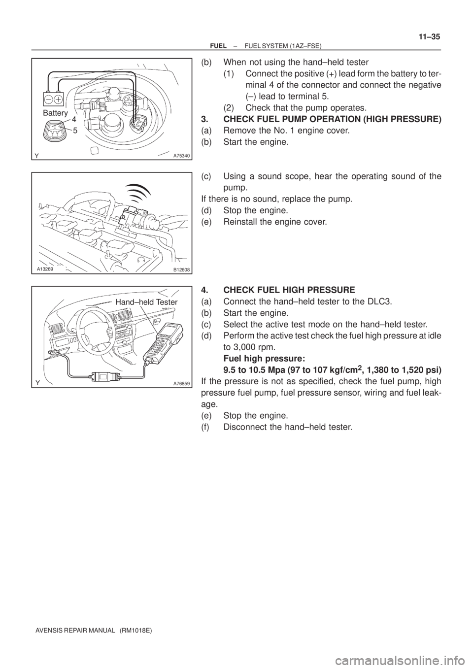
(b) When not using the hand±held tester
(1) Connect the positive (+) lead form the battery to ter-
minal 4 of the connector and connect the negative
(±) lead to terminal 5.
(2) Check that the pump operates.
3. CHECK FUEL PUMP OPERATION (HIGH PRESSURE)
(a) Remove the No. 1 engine cover.
(b) Start the engine.
(c) Using a sound scope, hear the operating sound of the
pump.
If there is no sound, replace the pump.
(d) Stop the engine.
(e) Reinstall the engine cover.
4. CHECK FUEL HIGH PRESSURE
(a) Connect the hand±held tester to the DLC3.
(b) Start the engine.
(c) Select the active test mode on the hand±held tester.
(d) Perform the active test check the fuel high pressure at idle
to 3,000 rpm.
Fuel high pressure:
9.5 to 10.5 Mpa (97 to 107 kgf/cm
2, 1,380 to 1,520 psi)
If the pressure is not as specified, check the fuel pump, high
pressure fuel pump, fuel pressure sensor, wiring and fuel leak-
age.
(e) Stop the engine.
(f) Disconnect the hand±held tester.
Page 783 of 1690
A60083
Fuel Pipe
Clamp No.1
A
A
B12941
B12944
A82344
Vinyl Bag or plastic Bag
± FUELFUEL SYSTEM (1AZ±FSE)
11±31
AVENSIS REPAIR MANUAL (RM1018E)
(b) Observe the following precautions when removing and
installing fuel injectors.
NOTICE:
Never reuse the O±ring.
(1) When installing a new O±ring to the injector, be
careful not to damage the injector.
(2) Coat the new O±ring with grease or gasoline before
installing. Never use engine oil, gear oil or brake oil.
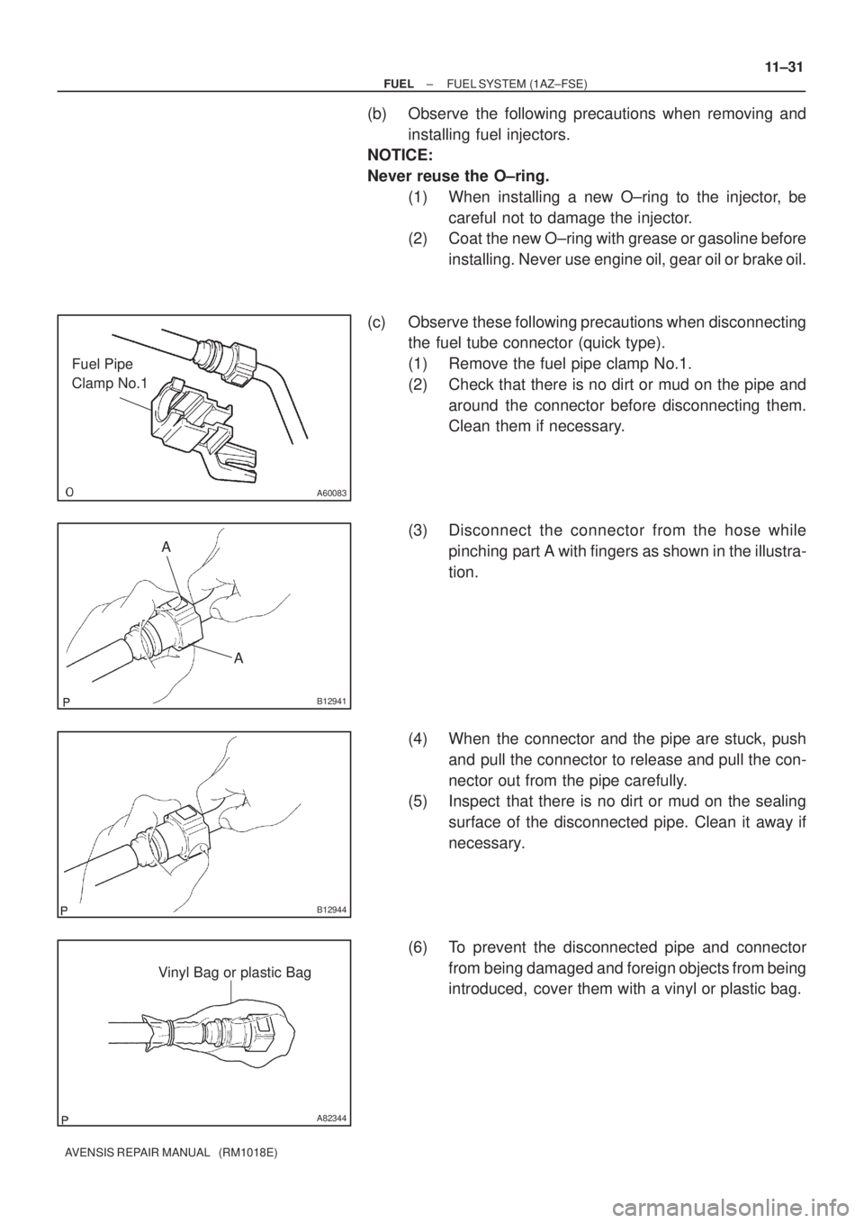
(c) Observe these following precautions when disconnecting
the fuel tube connector (quick type).
(1) Remove the fuel pipe clamp No.1.
(2) Check that there is no dirt or mud on the pipe and
around the connector before disconnecting them.
Clean them if necessary.
(3) Disconnect the connector from the hose while
pinching part A with fingers as shown in the illustra-
tion.
(4) When the connector and the pipe are stuck, push
and pull the connector to release and pull the con-
nector out from the pipe carefully.
(5) Inspect that there is no dirt or mud on the sealing
surface of the disconnected pipe. Clean it away if
necessary.
(6) To prevent the disconnected pipe and connector
from being damaged and foreign objects from being
introduced, cover them with a vinyl or plastic bag.
Page 784 of 1690
B16534Push
B16535Pull
11±32
±
FUEL FUEL SYSTEM(1AZ±FSE)
AVENSIS REPAIR MANUAL (RM1018E)
(d)Observe these precautions when connecting the fuel tube connectors (Quick Type):
(1)Check that there is no damage or foreign objects inthe connected part of the pipe.
(2)Match the axis of the connector with the axis of the pipe, and push into the connector until the connec-
tor makes a ºclickº sound. If the connection is tight,
apply little amount of fresh engine oil on the tip of the
pipe.
(3)After having finished the connection, check if the pipe and the connector are securely connected by
pulling on them.
(4)Check for fuel leaks.
4.CHECK FOR FUEL LEAKS
(a)Check that there are no fuel leaks after doing maintenance anywhere on t\
he fuel system. (See page 11±33)
Page 804 of 1690
A77894
A77891
A77892
A77893
Upper
Fuel Tank
Rear
Hose Clamp
A81617
Push 11±98
± FUELFUEL TANK ASSY (GASOLINE)
AVENSIS REPAIR MANUAL (RM1018E)
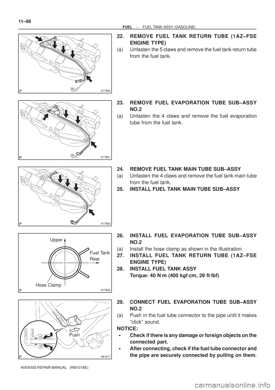
22. REMOVE FUEL TANK RETURN TUBE (1AZ±FSE
ENGINE TYPE)
(a) Unfasten the 5 claws and remove the fuel tank return tube
from the fuel tank.
23. REMOVE FUEL EVAPORATION TUBE SUB±ASSY
NO.2
(a) Unfasten the 4 claws and remove the fuel evaporation
tube from the fuel tank.
24. REMOVE FUEL TANK MAIN TUBE SUB±ASSY
(a) Unfasten the 4 claws and remove the fuel tank main tube
from the fuel tank.
25. INSTALL FUEL TANK MAIN TUBE SUB±ASSY
26. INSTALL FUEL EVAPORATION TUBE SUB±ASSY
NO.2
(a) Install the hose clamp as shown in the illustration.
27. INSTALL FUEL TANK RETURN TUBE (1AZ±FSE
ENGINE TYPE)
28. INSTALL FUEL TANK ASSY
Torque: 40 N�m (400 kgf�cm, 29 ft�lbf)
29. CONNECT FUEL EVAPORATION TUBE SUB±ASSY
NO.2
(a) Push in the fuel tube connector to the pipe until it makes
ºclickº sound.
NOTICE:
�Check if there is any damage or foreign objects on the
connected part.
�After connecting, check if the fuel tube connector and
the pipe are securely connected by pulling on them.
Page 805 of 1690
A81618
Push
2
1
Retainer
A77857
A78440
New Gasket
A77857
± FUELFUEL TANK ASSY (GASOLINE)
11±99
AVENSIS REPAIR MANUAL (RM1018E)
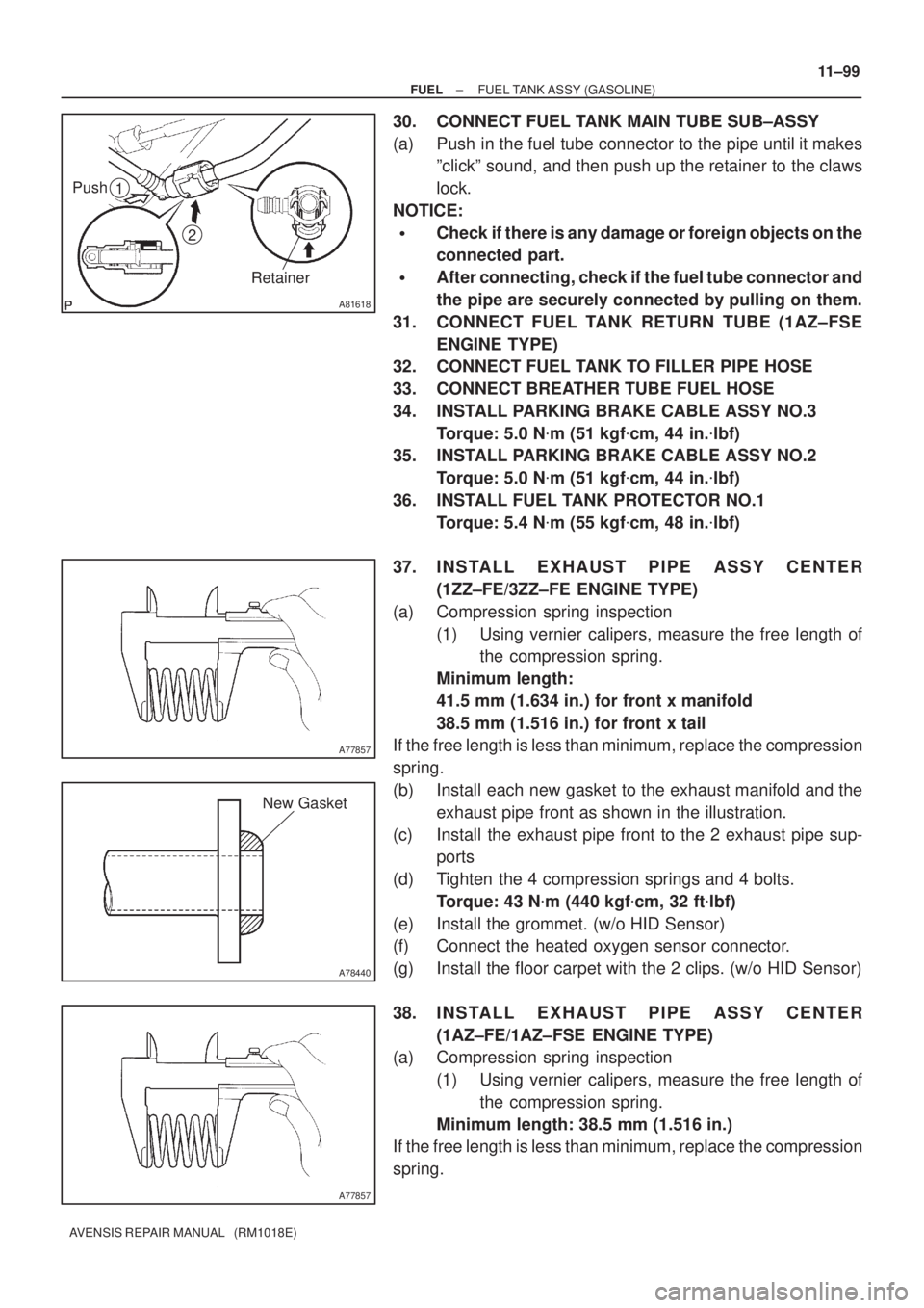
30. CONNECT FUEL TANK MAIN TUBE SUB±ASSY
(a) Push in the fuel tube connector to the pipe until it makes
ºclickº sound, and then push up the retainer to the claws
lock.
NOTICE:
�Check if there is any damage or foreign objects on the
connected part.
�After connecting, check if the fuel tube connector and
the pipe are securely connected by pulling on them.
31. CONNECT FUEL TANK RETURN TUBE (1AZ±FSE
ENGINE TYPE)
32. CONNECT FUEL TANK TO FILLER PIPE HOSE
33. CONNECT BREATHER TUBE FUEL HOSE
34. INSTALL PARKING BRAKE CABLE ASSY NO.3
Torque: 5.0 N�m (51 kgf�cm, 44 in.�lbf)
35. INSTALL PARKING BRAKE CABLE ASSY NO.2
Torque: 5.0 N�m (51 kgf�cm, 44 in.�lbf)
36. INSTALL FUEL TANK PROTECTOR NO.1
Torque: 5.4 N�m (55 kgf�cm, 48 in.�lbf)
37. INSTALL EXHAUST PIPE ASSY CENTER
(1ZZ±FE/3ZZ±FE ENGINE TYPE)
(a) Compression spring inspection
(1) Using vernier calipers, measure the free length of
the compression spring.
Minimum length:
41.5 mm (1.634 in.) for front x manifold
38.5 mm (1.516 in.) for front x tail
If the free length is less than minimum, replace the compression
spring.
(b) Install each new gasket to the exhaust manifold and the
exhaust pipe front as shown in the illustration.
(c) Install the exhaust pipe front to the 2 exhaust pipe sup-
ports
(d) Tighten the 4 compression springs and 4 bolts.
Torque: 43 N�m (440 kgf�cm, 32 ft�lbf)
(e) Install the grommet. (w/o HID Sensor)
(f) Connect the heated oxygen sensor connector.
(g) Install the floor carpet with the 2 clips. (w/o HID Sensor)
38. INSTALL EXHAUST PIPE ASSY CENTER
(1AZ±FE/1AZ±FSE ENGINE TYPE)
(a) Compression spring inspection
(1) Using vernier calipers, measure the free length of
the compression spring.
Minimum length: 38.5 mm (1.516 in.)
If the free length is less than minimum, replace the compression
spring.
Page 806 of 1690
A78440
New Gasket
11±100
±
FUEL FUEL TANK ASSY(GASOLINE)
AVENSIS REPAIR MANUAL (RM1018E)
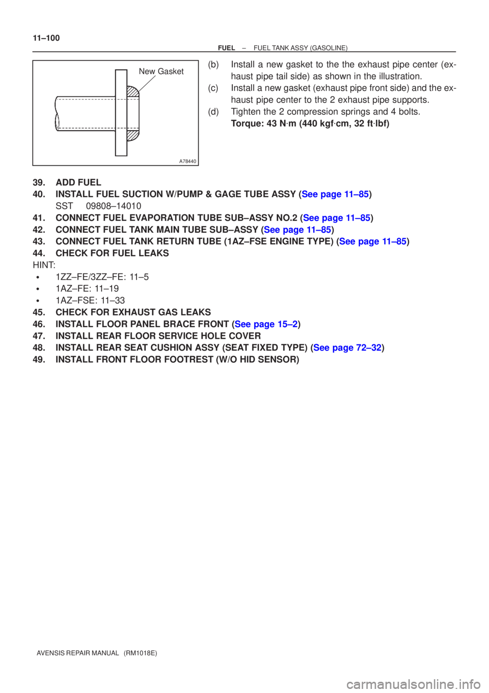
(b)Install a new gasket to the the exhaust pipe center (ex- haust pipe tail side) as shown in the illustration.
(c)Install a new gasket (exhaust pipe front side) and the ex-
haust pipe center to the 2 exhaust pipe supports.
(d)Tighten the 2 compression springs and 4 bolts. Torque: 43 N �m (440 kgf �cm, 32 ft �lbf)
39.ADD FUEL
40.INSTALL FUEL SUCTION W/PUMP & GAGE TUBE ASSY (See page 11±85) SST 09808±14010
41.CONNECT FUEL EVAPORATION TUBE SUB±ASSY NO.2 (See page 11±85)
42.CONNECT FUEL TANK MAIN TUBE SUB±ASSY (See page 11±85)
43.CONNECT FUEL TANK RETURN TUBE (1AZ±FSE ENGINE TYPE) (See page 11±85)
44. CHECK FOR FUEL LEAKS
HINT:
�1ZZ±FE/3ZZ±FE: 11±5
�1AZ±FE: 11±19
�1AZ±FSE: 11±33
45. CHECK FOR EXHAUST GAS LEAKS
46.INSTALL FLOOR PANEL BRACE FRONT (See page 15±2)
47. INSTALL REAR FLOOR SERVICE HOLE COVER
48.INSTALL REAR SEAT CUSHION ASSY (SEAT FIXED TYPE) (See page 72±32)
49. INSTALL FRONT FLOOR FOOTREST (W/O HID SENSOR)
Page 815 of 1690
A79149
SST
30 cm
(11.81 in.)
11±74
±
FUEL INJECTION OR SUPPLY PUMP ASSY(1CD±FTV)
AVENSIS REPAIR MANUAL (RM1018E)
46.INSTALL FUEL INLET PIPE SUB±ASSY
NOTICE:
�In case of having the injection pump replaced, must
replace the fuel inlet pipe, too.
�When assembling the pipe, perform the operation
with the engine cold under room temperature.
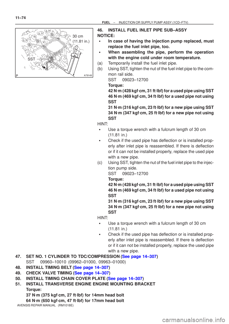
(a)Temporarily install the fuel inlet pipe.
(b)Using SST, tighten the nut of the fuel inlet pipe to the com-
mon rail side.
SST09023±12700
Torque:
42 N�m (428 kgf �cm, 31 ft �lbf) for a used pipe using SST
46 N �m (469 kgf �cm, 34 ft �lbf) for a used pipe not using
SST
31 N �m (316 kgf �cm, 23 ft �lbf) for a new pipe using SST
34 N �m (347 kgf �cm, 25 ft �lbf) for a new pipe not using
SST
HINT:
�Use a torque wrench with a fulcrum length of 30 cm
(11.81 in.)
�Check if the used pipe has deflection or is installed prop-
erly after inlet pipe is reassembled. If there is deflection
or if it can not be installed properly, replace the used pipe
with a new pipe.
(c)Using SST, tighten the nut of the fuel inlet pipe to the injec-
tion pump side.
SST09023±12700
Torque:
42 N�m (428 kgf �cm, 31 ft �lbf) for a used pipe using SST
46 N �m (469 kgf �cm, 34 ft �lbf) for a used pipe not using
SST
31 N �m (316 kgf �cm, 23 ft �lbf) for a new pipe using SST
34 N �m (347 kgf �cm, 25 ft �lbf) for a new pipe not using
SST
HINT:
�Use a torque wrench with a fulcrum length of 30 cm
(11.81 in.)
�Check if the used pipe has deflection or is installed prop-
erly after inlet pipe is reassembled. If there is deflection
or if it can not be installed properly, replace the used pipe
with a new pipe.
47.SET NO. 1 CYLINDER TO TDC/COMPRESSION(See page 14±307) SST 09960±10010 (09962±01000, 09963±01000)
48.INSTALL TIMING BELT(See page 14±307)
49.CHECK VALVE TIMING(See page 14±307)
50.INSTALL TIMING CHAIN COVER PLATE(See page 14±307)
51. INSTALL TRANSVERSE ENGINE ENGINE MOUNTING BRACKET Torque:
37 N�m (375 kgf �cm, 27 ft �lbf) for 14mm head bolt
64 N �m (650 kgf �cm, 47 ft �lbf) for 17mm head bolt