Page 603 of 1690

AVENSIS REPAIR MANUAL (RM1018E)
8.REMOVE TIMING GEAR CASE OR TIMIN")
Cut Position
A13332
A77419
SST
A13697
SST
SST
14±264
±
ENGINE MECHANICAL TIMING GEAR CASE OR TIMING CHAIN CASE OIL
SEAL(1AZ±FSE)
AVENSIS REPAIR MANUAL (RM1018E)
8.REMOVE TIMING GEAR CASE OR TIMING CHAIN CASE OIL SEAL
(a)Using a screwdriver with tip wrapped in the tape, pry out
the oil seal.
HINT:
After removal, check if the crankshaft is not damaged.
If it is damaged, smooth the surface with 400±grit sandpaper.
9.INSTALL TIMING GEAR CASE OR TIMING CHAIN CASE OIL SEAL
(a)Apply MP grease to a new oil seal lip.
NOTICE:
Keep the lip off foreign materials.
(b)Using SST and a hammer, tap in the oil seal until its sur- face is flush with the rear oil seal retainer edge.
SST09223±22010
NOTICE:
Wipe off extra grease on the crankshaft.
10.INSTALL CRANKSHAFT PULLEY
(a)Align the pulley set key with the key groove of the pulley.
(b)Using SST, install the pulley bolt. SST09213±54015 (91651±60855), 09330±00021
Torque: 170 N �m (1,733 kgf �cm, 125 ft �lbf)
11.INSTALL FAN AND GENERATOR V BELT (See page 14±185) SST 09249±63010
12. INSTALL ENGINE COVER SUB±ASSY NO.1 Torque: 7.0 N �m (71 kgf �cm, 62 in. �lbf)
13. INSTALL FRONT WHEEL RH Torque: 103 N �m (1,050 kgf �cm, 76 ft �lbf)
14. CHECK FOR ENGINE OIL LEAKS
Page 604 of 1690

AVENSIS REPAIR MANUAL (RM1018E)
VALVE C")
141B6±01
A77281
A77378
No. 1 Cylinder TDC/Compression
IN
EX
A77379
No. 4 Cylinder TDC/Compression
IN
EX
14±106
±
ENGINE MECHANICAL VALVE CLEARANCE(1AZ±FE)
AVENSIS REPAIR MANUAL (RM1018E)
VALVE CLEARANCE(1AZ±FE)
ADJUSTMENT
1.REMOVE RADIATOR SUPPORT OPENING COVER
2.REMOVE ENGINE ROOM COVER SIDE
3.REMOVE ENGINE UNDER COVER RH 4.REMOVE ENGINE COVER SUB±ASSY NO.1
(a)Remove 2 nuts and the engine cover No. 1.
5.REMOVE IGNITION COIL ASSY
(a)Remove 4 bolts and the ignition coils.
6.REMOVE CYLINDER HEAD COVER SUB±ASSY (See page 14±171)
7.SET NO. 1 CYLINDER TO TDC/COMPRESSION (See page 14±171) 8. INSPECT VALVE CLEARANCE
HINT:
Inspect and adjust the valve clearance when the engine is cold.
(a) Check only the valve indicated in the illustration.(1) Using a feeler gauge, measure the clearance be-tween the valve lifter and camshaft.
(2) Record the out±of specification valve clearance measurements. They will be used later to determine
the required replacement adjusting shim.
Valve clearance (Cold):
Intake 0.19 to 0.29 mm (0.0075 to 0.0114 in.)
Exhaust 0.30 to 0.40 mm (0.0118 to 0.0157 in.)
(b) Turn the crankshaft clockwise 1 revolution (360 �) and set
No. 4 cylinder to TDC/compression.
(c) Check only the valve indicated in the illustration. (1) Using a feeler gauge, measure the clearance be-tween the valve lifter and camshaft.
(2) Record the out±of specification valve clearance measurements. They will be used later to determine
the required replacement adjusting shim.
Valve clearance (Cold):
Intake 0.19 to 0.29 mm (0.0075 to 0.0114 in.)
Exhaust 0.30 to 0.40 mm (0.0118 to 0.0157 in.)
Page 608 of 1690
14±110
±
ENGINE MECHANICAL VALVE CLEARANCE(1AZ±FE)
AVENSIS REPAIR MANUAL (RM1018E)
(h)Install the camshafts. (See page 14±171)
(i)Install the chain tensioner. (See page 14±171)
10.INSTALL CYLINDER HEAD COVER SUB±ASSY (See page 14±171)
11. INSTALL IGNITION COIL ASSY
Torque: 9.0 N �m (92 kgf �cm, 80 in. �lbf)
12. CHECK FOR ENGINE OIL LEAKS
13. INSTALL ENGINE COVER SUB±ASSY NO.1 Torque: 7.0 N �m (71 kgf �cm, 62 in. �lbf)
Page 610 of 1690

14±7
AVENSIS REPAIR MANUAL (RM1018E)
6. DISCONNECT VENTILA")
A64058
A64856
A62185
Mark
Mark
Mark
Timing Chain
Cover Surface
Timing
Notch
A01131
± ENGINE MECHANICALVALVE CLEARANCE (1ZZ±FE/3ZZ±FE)
14±7
AVENSIS REPAIR MANUAL (RM1018E)
6. DISCONNECT VENTILATION HOSE NO.2
(a) Disconnect the ventilation hose from the cylinder head
cover.
7. REMOVE CYLINDER HEAD COVER SUB±ASSY
(a) Remove the 9 bolts, 2 seal washers, 2 nuts, 3 clamp
brackets and cylinder head cover.
8. REMOVE ENGINE UNDER COVER SUB±ASSY NO.1
9. REMOVE ENGINE UNDER COVER RH
10. SET NO. 1 CYLINDER TO TDC/COMPRESSION
(a) Turn the crankshaft pulley, and align the timing notch with
timing mark º0º of the timing chain cover.
(b) Check that the point marks of the camshaft timing sprock-
et and VVT timing sprocket are in straight line on the tim-
ing chain cover surface as shown in the illustration.
HINT:
If not, turn the crankshaft 1 revolution (360�) and align the
marks as above.
11. INSPECT VALVE CLEARANCE
(a) Check the valves indicated in the illustration.
(1) Using a feeler gauge, measure the clearance be-
tween the valve lifter and the camshaft.
(2) Record the out±of specification valve clearance
measurements. They will be used later to determine
the required replacement valve lifter.
Valve clearance (Cold):
Intake 0.15 to 0.25 mm (0.0059 to 0.0098 in.)
Exhaust 0.25 to 0.35 mm (0.0098 to 0.0138 in.)
Page 611 of 1690

AVENSIS REPAIR MANUAL (RM1018E)
(b) Turn the crankshaft 1 revolution (360 �) and set No. 4 cyl-
inder to TDC/c")
A01132
A60622
A01045
A64005
14±8
± ENGINE MECHANICALVALVE CLEARANCE (1ZZ±FE/3ZZ±FE)
AVENSIS REPAIR MANUAL (RM1018E)
(b) Turn the crankshaft 1 revolution (360 �) and set No. 4 cyl-
inder to TDC/compression.
(c) Check the valves indicated in the illustration.
(1) Using a feeler gauge, measure the clearance be-
tween the valve lifter and camshaft.
(2) Record the out±of specification valve clearance
measurements. They will be used later to determine
the required replacement valve lifter.
Valve clearance (Cold):
Intake 0.15 to 0.25 mm (0.0059 to 0.0098 in.)
Exhaust 0.25 to 0.35 mm (0.0098 to 0.0138 in.)
12. REMOVE FAN AND GENERATOR V BELT
(a) Turn the V±ribbed belt tensioner clockwise slowly and
loosen it. Then, remove the fan and generator V belt and
put back the V±ribbed belt tensioner carefully.
13. REMOVE ENGINE MOUNTING INSULATOR
SUB±ASSY RH
(a) Place a wooden block on a jack underneath the engine.
Remove the 4 bolts and 2 nuts and detach the engine
mounting insulator RH.
Page 618 of 1690
A62187
Hold
Tighten
A62185
Mark
Mark
Mark
Timing Chain
Cover Surface
Timing
Notch
A62177
Raise
Push
Hook
Pin
A62178
Push
± ENGINE MECHANICALVALVE CLEARANCE (1ZZ±FE/3ZZ±FE)
14±15
AVENSIS REPAIR MANUAL (RM1018E)
(s) Hold the camshaft with a wrench, tighten the camshaft
timing gear set bolt.
Torque: 54 N�m (551 kgf�cm, 40 ft�lbf)
NOTICE:
Be careful not damage the valve lifter.
(t) Check the match marks on the 2 camshaft sprockets are
aligned with each other and aligned with the painted links
of the timing chain as shown in the illustration. Also, check
the timing notch is aligned with the timing mark º0º of the
chain cover.
(u) Install chain tensioner.
(1) Check that the O±ring is clean, and set the hook as
shown in the illustration.
(2) Apply engine oil to the chain tensioner and install it
with the 2 nuts.
Torque: 9.0 N�m (92 kgf�cm, 80 in�lbf)
NOTICE:
If the hook released the plunger during installation, re±
hook the plunger by the hook to fixit.
Page 619 of 1690
A62180
Disconnect
Hook
Pin Turn
A62181
Plunger
Turn
Push
A11858
A64005
14±16
± ENGINE MECHANICALVALVE CLEARANCE (1ZZ±FE/3ZZ±FE)
AVENSIS REPAIR MANUAL (RM1018E)
(3) Turn the crankshaft counterclockwise, and take the
hook off the knock pin to release the plunger.
(4) Turn the crankshaft clockwise, and check that the
plunger is extended.
HINT:
If the plunger does not be extended, press the slipper into the
chain tensioner using a screwdriver so that the hook is took off
from the knock pin and let the plunger can be extended.
16. INSTALL V±RIBBED BELT TENSIONER ASSY
(a) Install the V±ribbed belt tensioner with the nut and bolt.
Torque:
29 N�m (296 kgf�cm, 21 ft�lbf) for Nut
69 N�m (704 kgf�cm, 51 ft�lbf) for Bolt
17. INSTALL ENGINE MOUNTING INSULATOR
SUB±ASSY RH
(a) Install the engine mounting insulator with the 4 bolts and
2 nuts.
Torque: 52 N�m (530 kgf�cm, 38 ft�lbf)
Page 621 of 1690
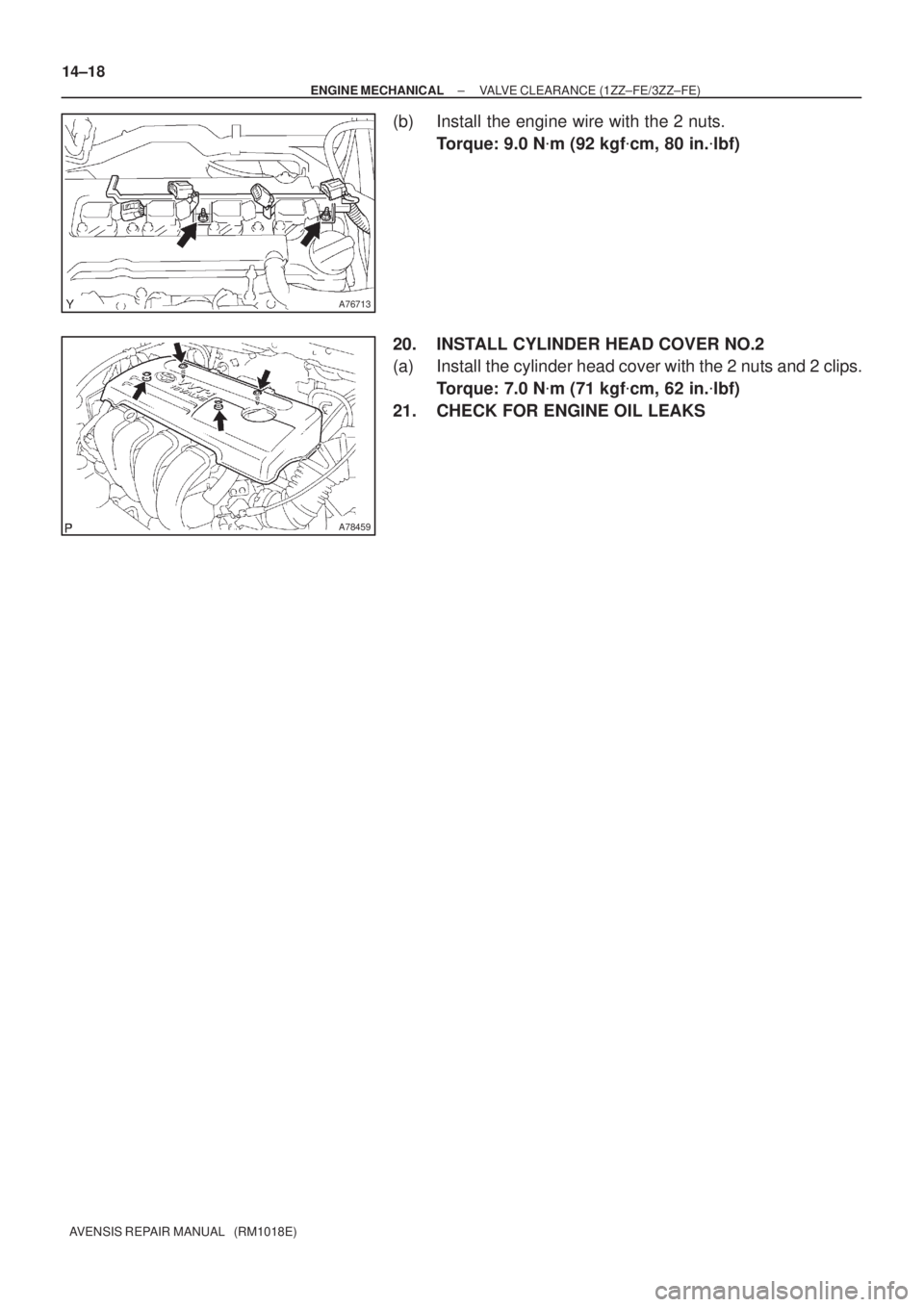
A76713
A78459
14±18
± ENGINE MECHANICALVALVE CLEARANCE (1ZZ±FE/3ZZ±FE)
AVENSIS REPAIR MANUAL (RM1018E)
(b) Install the engine wire with the 2 nuts.
Torque: 9.0 N�m (92 kgf�cm, 80 in.�lbf)
20. INSTALL CYLINDER HEAD COVER NO.2
(a) Install the cylinder head cover with the 2 nuts and 2 clips.
Torque: 7.0 N�m (71 kgf�cm, 62 in.�lbf)
21. CHECK FOR ENGINE OIL LEAKS

AVENSIS REPAIR MANUAL (RM1018E)
(h)Install the camshafts. (See page 14±171)
(i)Install the chain tensioner. (See page 14±171)
10.INSTALL CYLIN")

14±15
AVENSIS REPAIR M")

AVENSIS REPAIR MANUAL (RM1018E)
(3) Turn the crankshaft counterclo")