Page 499 of 1690
± ENGINE MECHANICALENGINE (1ZZ±FE/3ZZ±FE)
14±3
AVENSIS REPAIR MANUAL (RM1018E)
(3) While cranking the engine, measure the compres-
sion pressure.
Compression pressure
�
1,300 kPa (13.3 kgf�cm
2, 189 psi)
Minimum pressure: 1,000 kPa (10.2 kgf�cm
2, 145 psi)
Difference between each cylinder:
100 kPa (1.0 kgf�cm
2, 14 psi)
NOTICE:
�Always use a fully charged battery to obtain engine
speed of 250 rpm or more.
�Check other cylinder's compression pressure in the
same way.
�This measurement must be done in as short a time as
possible.
(4) If the cylinder compression in one or more cylinders
is low, pour a small amount of engine oil into the cyl-
inder through the spark plug hole and repeat steps
(1) through (3) for the cylinders that have low com-
pression.
HINT:
�If adding oil helps increase the compression, the piston
rings and/or cylinder bore may be worn or damaged.
�If pressure stays low, a valve may be sticking or seating
improperly, or there may be leakage past the gasket.
10. INSPECT CO/HC
(a) Start the engine.
(b) Run the engine at 2,500 rpm for approximately 180 seconds.
(c) Insert CO/HC meter testing probe at least 40 cm (1.3 ft) into the tailpipe during idling.
(d) Check CO/HC concentration at idle.
Idle CO concentration: 0 to 0.5 %
Idle HC concentration: Applicable local regulation
If the CO/HC concentration does not conform to specifications, perform troubleshooting in the order given
below.
�Check heated oxygen sensor operation.
�See the table below for possible causes, and then inspect and repair the applicable causes if
necessary.
Page 501 of 1690
141BI±01
A77421
Cut Position
A77422SST
14±180
±
ENGINE MECHANICAL ENGINE REAR OIL SEAL(1AZ±FE)
AVENSIS REPAIR MANUAL (RM1018E)
ENGINE REAR OIL SEAL(1AZ±FE)
REPLACEMENT
1.REMOVE MANUAL TRANSAXLE ASSY (M/T TRANSAXLE) (See page 41±24)
2.REMOVE AUTOMATIC TRANSAXLE ASSY (A/T TRANSAXLE) (See page 40±25)
3.REMOVE CLUTCH COVER ASSY (M/T TRANSAXLE) (See page 42±26)
4.REMOVE DRIVE PLATE AND RING GEAR OR FLYWHEEL (See page 14±121) SST09213±54015 (91651±60855), 09330±00021
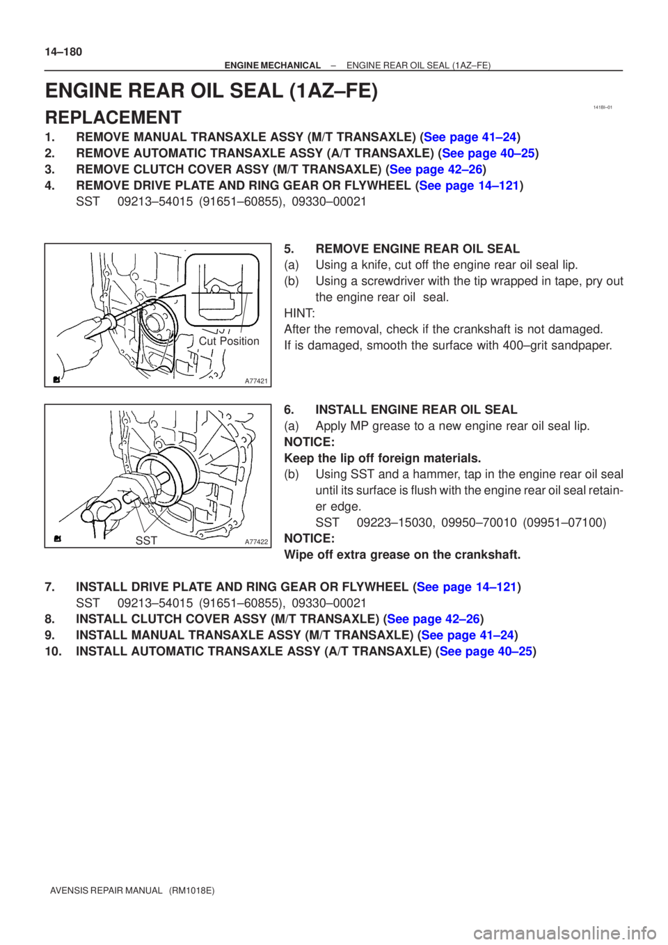
5.REMOVE ENGINE REAR OIL SEAL
(a)Using a knife, cut off the engine rear oil seal lip.
(b)Using a screwdriver with the tip wrapped in tape, pry outthe engine rear oil seal.
HINT:
After the removal, check if the crankshaft is not damaged.
If is damaged, smooth the surface with 400±grit sandpaper.
6.INSTALL ENGINE REAR OIL SEAL
(a)Apply MP grease to a new engine rear oil seal lip.
NOTICE:
Keep the lip off foreign materials.
(b)Using SST and a hammer, tap in the engine rear oil seal until its surface is flush with the engine rear oil seal retain-
er edge.
SST09223±15030, 09950±70010 (09951±07100)
NOTICE:
Wipe off extra grease on the crankshaft.
7.INSTALL DRIVE PLATE AND RING GEAR OR FLYWHEEL (See page 14±121) SST09213±54015 (91651±60855), 09330±00021
8.INSTALL CLUTCH COVER ASSY (M/T TRANSAXLE) (See page 42±26)
9.INSTALL MANUAL TRANSAXLE ASSY (M/T TRANSAXLE) (See page 41±24)
10.INSTALL AUTOMATIC TRANSAXLE ASSY (A/T TRANSAXLE) (See page 40±25)
Page 502 of 1690
141BS±01
A77421
Cut Position
A77422SST
±
ENGINE MECHANICAL ENGINE REAR OIL SEAL(1AZ±FSE)
14±265
AVENSIS REPAIR MANUAL (RM1018E)
ENGINE REAR OIL SEAL(1AZ±FSE)
REPLACEMENT
1.REMOVE MANUAL TRANSAXLE ASSY (M/T TRANSAXLE) (See page 41±24)
2.REMOVE AUTOMATIC TRANSAXLE ASSY (A/T TRANSAXLE) (See page 40±25)
3.REMOVE CLUTCH COVER ASSY (M/T TRANSAXLE) (See page 42±26)
4.REMOVE DRIVE PLATE AND RING GEAR OR FLYWHEEL (See page 14±204)
SST09213±54015 (91651±60855), 09330±00021
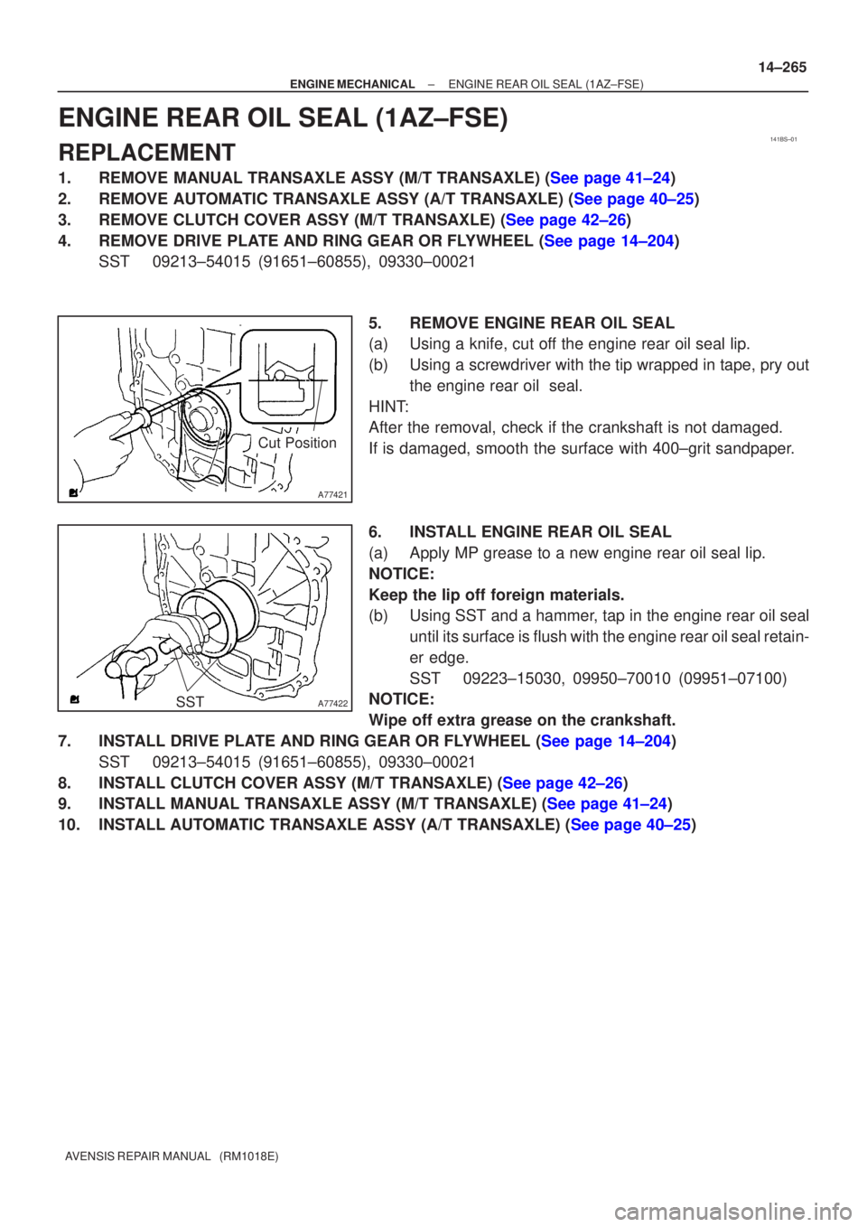
5.REMOVE ENGINE REAR OIL SEAL
(a)Using a knife, cut off the engine rear oil seal lip.
(b)Using a screwdriver with the tip wrapped in tape, pry outthe engine rear oil seal.
HINT:
After the removal, check if the crankshaft is not damaged.
If is damaged, smooth the surface with 400±grit sandpaper.
6.INSTALL ENGINE REAR OIL SEAL
(a)Apply MP grease to a new engine rear oil seal lip.
NOTICE:
Keep the lip off foreign materials.
(b)Using SST and a hammer, tap in the engine rear oil seal until its surface is flush with the engine rear oil seal retain-
er edge.
SST09223±15030, 09950±70010 (09951±07100)
NOTICE:
Wipe off extra grease on the crankshaft.
7.INSTALL DRIVE PLATE AND RING GEAR OR FLYWHEEL (See page 14±204) SST 09213±54015 (91651±60855), 09330±00021
8.INSTALL CLUTCH COVER ASSY (M/T TRANSAXLE) (See page 42±26)
9.INSTALL MANUAL TRANSAXLE ASSY (M/T TRANSAXLE) (See page 41±24)
10.INSTALL AUTOMATIC TRANSAXLE ASSY (A/T TRANSAXLE) (See page 40±25)
Page 503 of 1690
141CC±01
A61182
SST
A09447
SST
A09448
±
ENGINE MECHANICAL ENGINE REAR OIL SEAL(1CD±FTV)
14±345
AVENSIS REPAIR MANUAL (RM1018E)
ENGINE REAR OIL SEAL(1CD±FTV)
REPLACEMENT
1.REMOVE MANUAL TRANSAXLE ASSY (See page 41±33)
SST 09930±00010, 09628±62011, 09520±01010, 09520±24010 (09520±32040)
2.REMOVE CLUTCH COVER ASSY (See page 42±26)
3.REMOVE CLUTCH DISC ASSY (See page 42±26)
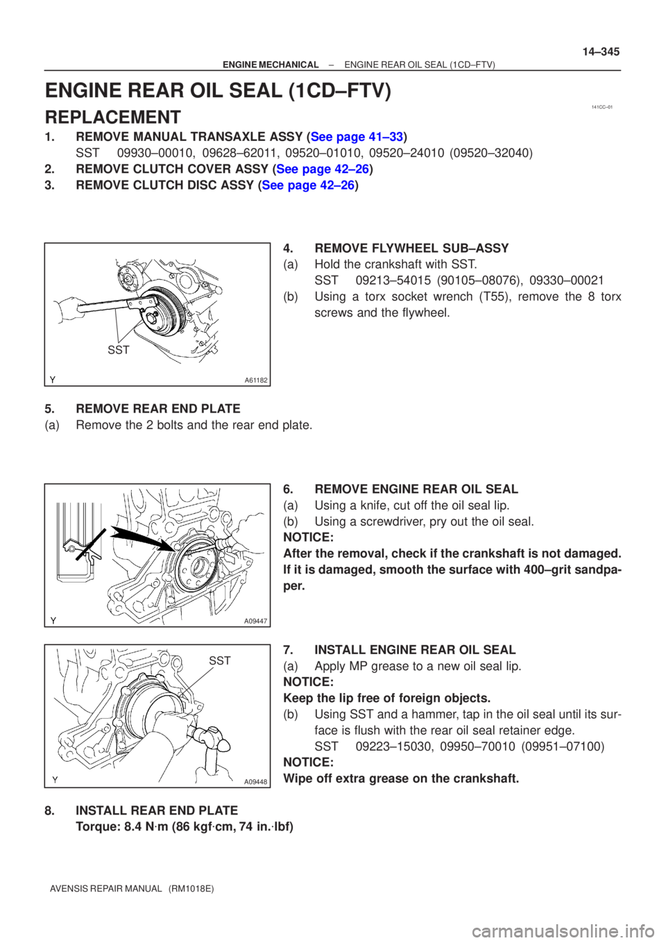
4. REMOVE FLYWHEEL SUB±ASSY
(a) Hold the crankshaft with SST.SST 09213±54015 (90105±08076), 09330±00021
(b) Using a torx socket wrench (T55), remove the 8 torx screws and the flywheel.
5. REMOVE REAR END PLATE
(a) Remove the 2 bolts and the rear end plate. 6. REMOVE ENGINE REAR OIL SEAL
(a) Using a knife, cut off the oil seal lip.
(b) Using a screwdriver, pry out the oil seal.
NOTICE:
After the removal, check if the crankshaft is not damaged.
If it is damaged, smooth the surface with 400±grit sandpa-
per.
7. INSTALL ENGINE REAR OIL SEAL
(a) Apply MP grease to a new oil seal lip.
NOTICE:
Keep the lip free of foreign objects.
(b) Using SST and a hammer, tap in the oil seal until its sur-face is flush with the rear oil seal retainer edge.
SST 09223±15030, 09950±70010 (09951±07100)
NOTICE:
Wipe off extra grease on the crankshaft.
8. INSTALL REAR END PLATE Torque: 8.4 N �m (86 kgf �cm, 74 in. �lbf)
Page 505 of 1690
141CO±01
A62838SST
A62838SST
A62202
Cut Position
A62203
SST
14±98
±
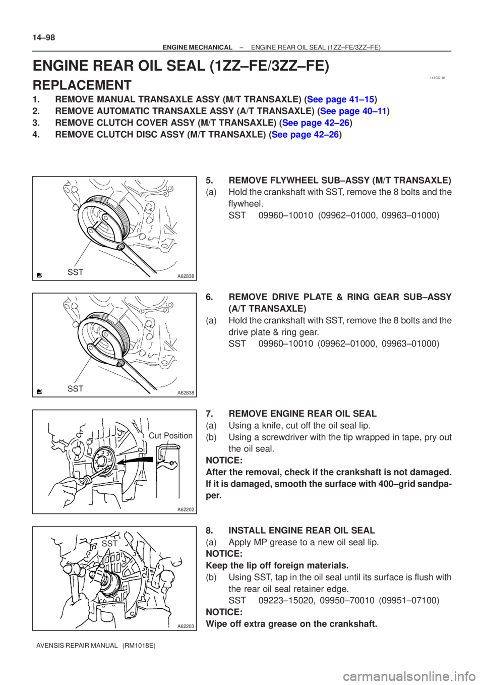
ENGINE MECHANICAL ENGINE REAR OIL SEAL(1ZZ±FE/3ZZ±FE)
AVENSIS REPAIR MANUAL (RM1018E)
ENGINE REAR OIL SEAL(1ZZ±FE/3ZZ±FE)
REPLACEMENT
1.REMOVE MANUAL TRANSAXLE ASSY (M/T TRANSAXLE) (See page 41±15)
2.REMOVE AUTOMATIC TRANSAXLE ASSY (A/T TRANSAXLE) (See page 40±11)
3.REMOVE CLUTCH COVER ASSY (M/T TRANSAXLE) (See page 42±26)
4.REMOVE CLUTCH DISC ASSY (M/T TRANSAXLE) (See page 42±26) 5. REMOVE FLYWHEEL SUB±ASSY (M/T TRANSAXLE)
(a) Hold the crankshaft with SST, remove the 8 bolts and theflywheel.
SST 09960±10010 (09962±01000, 09963±01000)
6. REMOVE DRIVE PLATE & RING GEAR SUB±ASSY (A/T TRANSAXLE)
(a) Hold the crankshaft with SST, remove the 8 bolts and the drive plate & ring gear.
SST 09960±10010 (09962±01000, 09963±01000)
7. REMOVE ENGINE REAR OIL SEAL
(a) Using a knife, cut off the oil seal lip.
(b) Using a screwdriver with the tip wrapped in tape, pry out the oil seal.
NOTICE:
After the removal, check if the crankshaft is not damaged.
If it is damaged, smooth the surface with 400±grid sandpa-
per.
8. INSTALL ENGINE REAR OIL SEAL
(a) Apply MP grease to a new oil seal lip.
NOTICE:
Keep the lip off foreign materials.
(b) Using SST, tap in the oil seal until its surface is flush with the rear oil seal retainer edge.
SST 09223±15020, 09950±70010 (09951±07100)
NOTICE:
Wipe off extra grease on the crankshaft.
Page 506 of 1690
A62838SST
A62205
1
5
3
82
6
4
7
A62206
90 �
A62838SST
A62204
1
5
3
82
6
4
7
±
ENGINE MECHANICAL ENGINE REAR OIL SEAL(1ZZ±FE/3ZZ±FE)
14±99
AVENSIS REPAIR MANUAL (RM1018E)
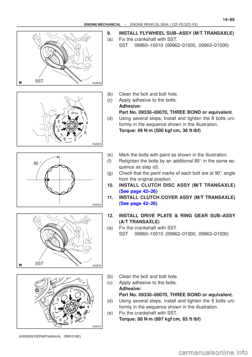
9.INSTALL FLYWHEEL SUB±ASSY (M/T TRANSAXLE)
(a)Fix the crankshaft with SST.
SST09960±10010 (09962±01000, 09963±01000)
(b)Clean the bolt and bolt hole.
(c)Apply adhesive to the bolts. Adhesive:
Part No. 09330±00070, THREE BOND or equivalent.
(d)Using several steps, Install and tighten the 8 bolts uni- formly in the sequence shown in the illustration.
Torque: 49 N �m (500 kgf �cm, 36 ft �lbf)
(e)Mark the bolts with paint as shown in the illustration.
(f)Retighten the bolts by an additional 90 � in the same se-
quence as step (d).
(g)Check that the paint marks of each bolt are at 90 � angle
from the original position.
10.INSTALL CLUTCH DISC ASSY (M/T TRANSAXLE) (See page 42±26)
11. INSTALL CLUTCH COVER ASSY (M/T TRANSAXLE) (See page 42±26)
12. INSTALL DRIVE PLATE & RING GEAR SUB±ASSY (A/T TRANSAXLE)
(a) Fix the crankshaft with SST. SST 09960±10010 (09962±01000, 09963±01000)
(b) Clean the bolt and bolt hole.
(c) Apply adhesive to the bolts. Adhesive:
Part No. 09330±00070, THREE BOND or equivalent.
(d) Using several steps, install and tighten the 8 bolts uni- formly in the sequence shown in the illustration.
(e) Fix the crankshaft with SST.
Torque: 88 N �m (897 kgf �cm, 65 ft �lbf)
Page 534 of 1690
14±134
±
ENGINE MECHANICAL PARTIAL ENGINE ASSY(1AZ±FE)
AVENSIS REPAIR MANUAL (RM1018E)
155.INSTALL RADIATOR ASSY (See page 16±24)
156.INSTALL RADIATOR RELAY BLOCK Torque: 5.0 N �m (51 kgf �cm,44 in. �lbf)
157.INSTALL ENGINE COVER SUB±ASSY NO.1 Torque: 7.0 N �m (71 kgf �cm,62 in. �lbf)
158.ADD MANUAL TRANSAXLE OIL (M/T TRANSAXLE)
159.ADD AUTOMATIC TRANSAXLE FLUID (A/T TRANSAXLE)
160.ADD ENGINE OIL
161.ADD COOLANT (See page 16±19)
162. ADD POWER STEERING FLUID
163. BLEED POWER STEERING FLUID
164. CHECK FOR ENGINE OIL LEAKS
165.CHECK FOR ENGINE COOLANT LEAKS (See page 16±13)
166.CHECK FOR FUEL LEAKS (See page 11±15)
167. INSTALL FRONT WHEELS Torque: 103 N �m (1,050 kgf �cm, 76 ft �lbf)
168.ADJUST FRONT WHEEL ALIGNMENT (See page 26±6)
169.INSPECT CHECK IDLE SPEED AND IGNITION TIMING (See page 14±101)
170.INSPECT CO/HC (See page 14±101)
171. CHECK ABS SPEED SENSOR SIGNAL
Page 542 of 1690
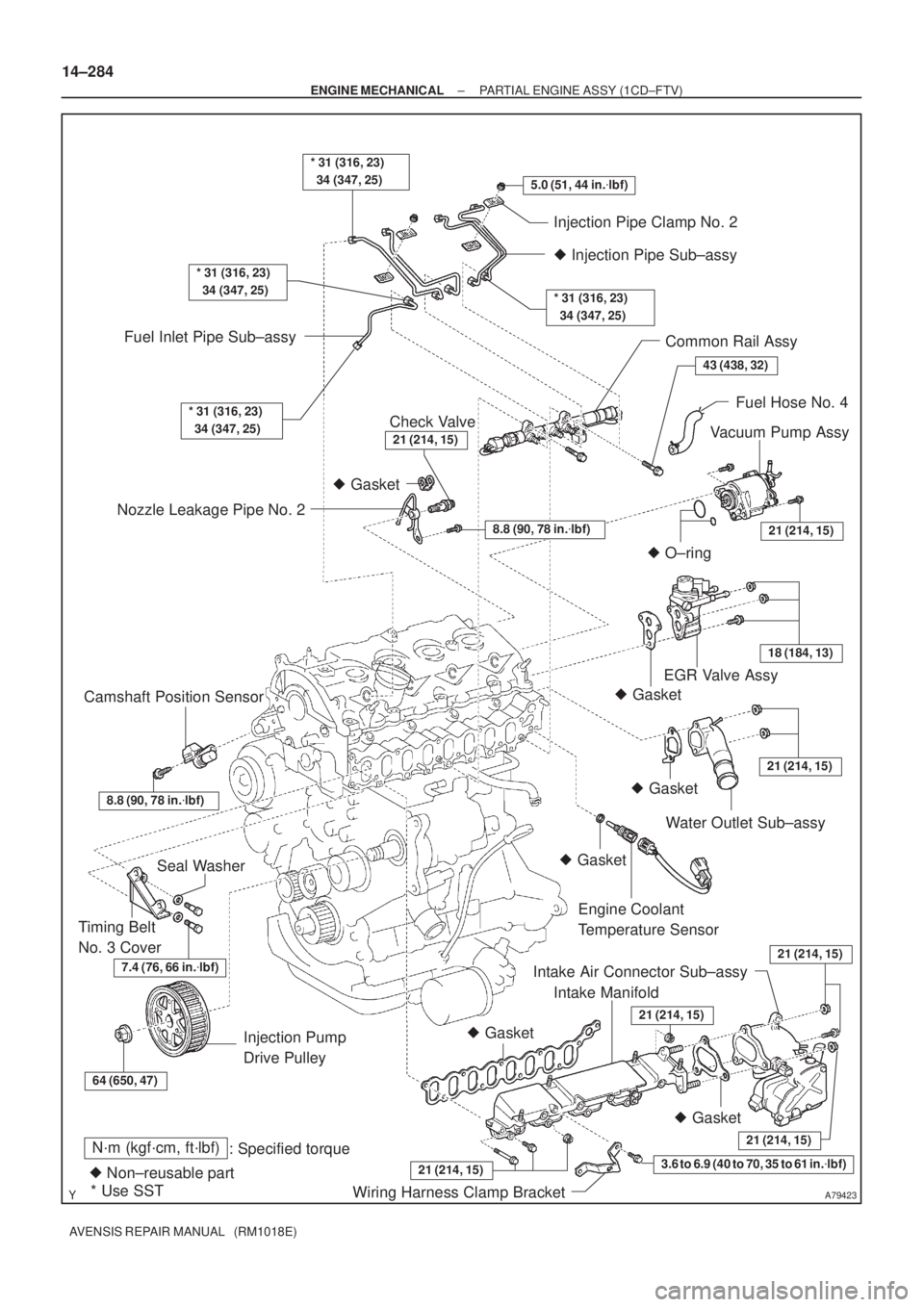
A79423
N´m (kgf´cm, ft´lbf)
: Specified torque
� Non±reusable part� Gasket
� O±ring
* Use SST� Gasket � Gasket
� Gasket
� Gasket
� Gasket3.6 to 6.9 (40 to 70, 35 to 61 in.�lbf)
5.0 (51, 44 in.�lbf)
7.4 (76, 66 in.�lbf)
* 31 (316, 23)
34 (347, 25)
43 (438, 32)
21 (214, 15)
18 (184, 13)
21 (214, 15)
21 (214, 15)
21 (214, 15)
64 (650, 47)
21 (214, 15)
* 31 (316, 23)
34 (347, 25)
* 31 (316, 23)
34 (347, 25)
Injection Pipe Clamp No. 2
� Injection Pipe Sub±assy
* 31 (316, 23)
34 (347, 25)
Common Rail Assy
Fuel Hose No. 4
Vacuum Pump Assy
Nozzle Leakage Pipe No. 2Fuel Inlet Pipe Sub±assy
EGR Valve Assy
Water Outlet Sub±assy
Engine Coolant
Temperature Sensor
Intake Air Connector Sub±assy
Intake Manifold
Wiring Harness Clamp Bracket Injection Pump
Drive Pulley Timing Belt
No. 3 CoverSeal Washer Camshaft Position Sensor
Check Valve
8.8 (90, 78 in.�lbf)
8.8 (90, 78 in.�lbf)
21 (214, 15)
21 (214, 15)
14±284
± ENGINE MECHANICALPARTIAL ENGINE ASSY (1CD±FTV)
AVENSIS REPAIR MANUAL (RM1018E)