Page 727 of 1690
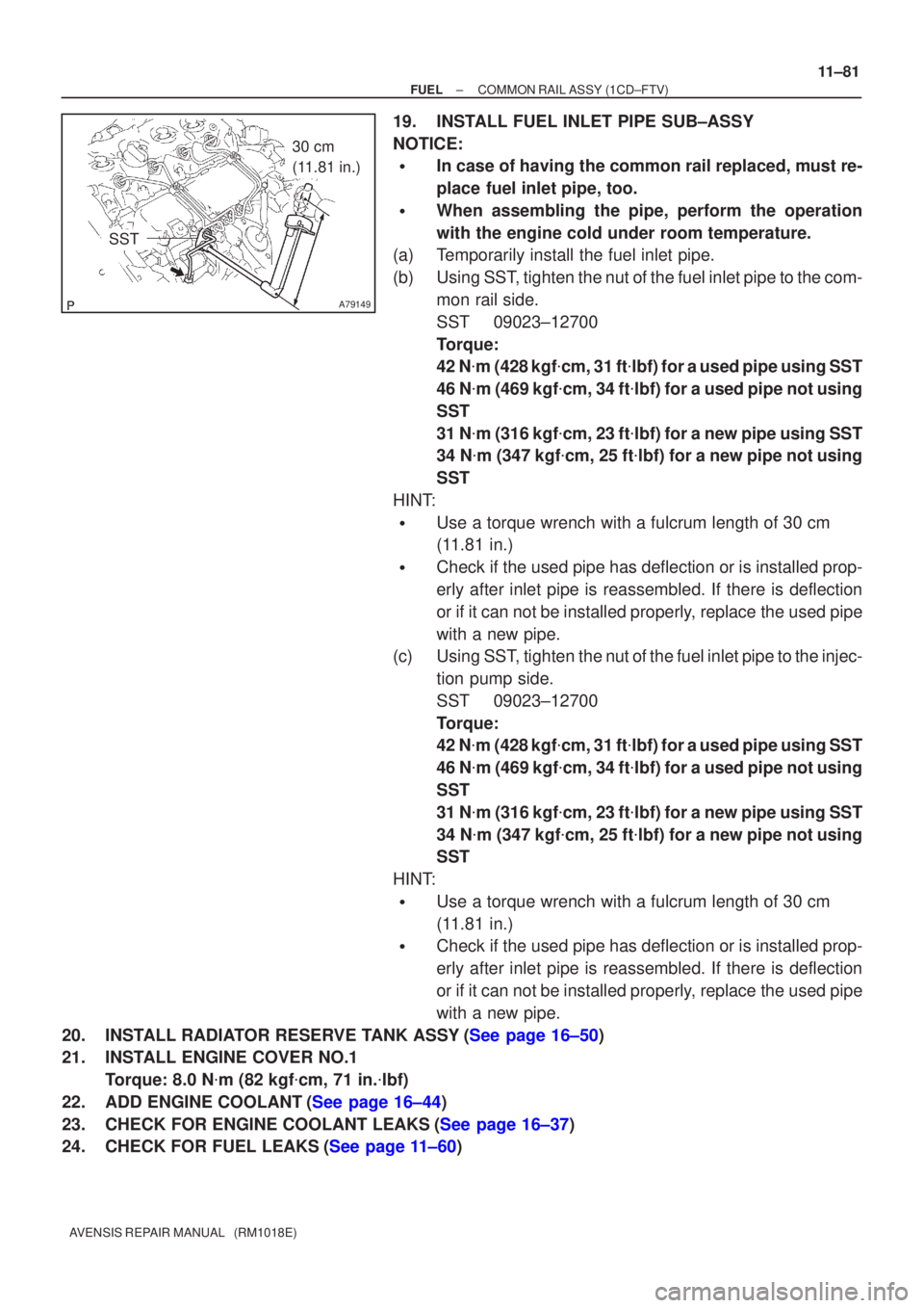
A79149
30 cm
(11.81 in.)
SST
±
FUEL COMMON RAIL ASSY(1CD±FTV)
11±81
AVENSIS REPAIR MANUAL (RM1018E)
19.INSTALL FUEL INLET PIPE SUB±ASSY
NOTICE:
�In case of having the common rail replaced, must re-
place fuel inlet pipe, too.
�When assembling the pipe, perform the operation
with the engine cold under room temperature.
(a)Temporarily install the fuel inlet pipe.
(b)Using SST, tighten the nut of the fuel inlet pipe to the com-
mon rail side.
SST09023±12700
Torque:
42 N�m (428 kgf �cm, 31 ft �lbf) for a used pipe using SST
46 N �m (469 kgf �cm, 34 ft �lbf) for a used pipe not using
SST
31 N �m (316 kgf �cm, 23 ft �lbf) for a new pipe using SST
34 N �m (347 kgf �cm, 25 ft �lbf) for a new pipe not using
SST
HINT:
�Use a torque wrench with a fulcrum length of 30 cm
(11.81 in.)
�Check if the used pipe has deflection or is installed prop-
erly after inlet pipe is reassembled. If there is deflection
or if it can not be installed properly, replace the used pipe
with a new pipe.
(c)Using SST, tighten the nut of the fuel inlet pipe to the injec-
tion pump side.
SST09023±12700
Torque:
42 N�m (428 kgf �cm, 31 ft �lbf) for a used pipe using SST
46 N �m (469 kgf �cm, 34 ft �lbf) for a used pipe not using
SST
31 N �m (316 kgf �cm, 23 ft �lbf) for a new pipe using SST
34 N �m (347 kgf �cm, 25 ft �lbf) for a new pipe not using
SST
HINT:
�Use a torque wrench with a fulcrum length of 30 cm
(11.81 in.)
�Check if the used pipe has deflection or is installed prop-
erly after inlet pipe is reassembled. If there is deflection
or if it can not be installed properly, replace the used pipe
with a new pipe.
20.INSTALL RADIATOR RESERVE TANK ASSY(See page 16±50)
21. INSTALL ENGINE COVER NO.1 Torque: 8.0 N �m (82 kgf �cm, 71 in. �lbf)
22.ADD ENGINE COOLANT(See page 16±44)
23.CHECK FOR ENGINE COOLANT LEAKS(See page 16±37)
24.CHECK FOR FUEL LEAKS(See page 11±60)
Page 732 of 1690
110U1±01
A77908
Retainer
(at 4 places)
Insert
SST
Turn
Fuel Pipe
Clamp
A76220
O±ring
Nylon Tube HousingPipe
Retainer
A77909
11±26
±
FUEL FUEL INJECTOR ASSY(1AZ±FE)
AVENSIS REPAIR MANUAL (RM1018E)
REPLACEMENT
1.DISCHARGE FUEL SYSTEM PRESSURE (See page 11±15)
2.REMOVE ENGINE COVER SUB±ASSY NO.1 (See page 10±26)
3.REMOVE AIR CLEANER CAP SUB±ASSY (See page 10±26) 4. DISCONNECT FUEL TUBE SUB±ASSY
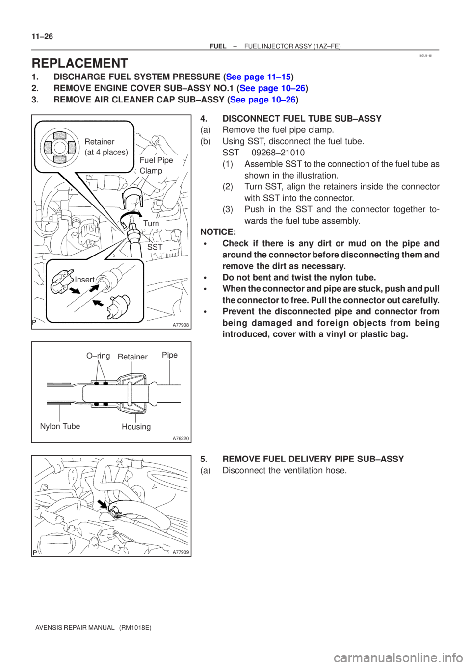
(a) Remove the fuel pipe clamp.
(b) Using SST, disconnect the fuel tube.SST 09268±21010
(1) Assemble SST to the connection of the fuel tube asshown in the illustration.
(2) Turn SST, align the retainers inside the connector
with SST into the connector.
(3) Push in the SST and the connector together to- wards the fuel tube assembly.
NOTICE:
�Check if there is any dirt or mud on the pipe and
around the connector before disconnecting them and
remove the dirt as necessary.
�Do not bent and twist the nylon tube.
�When the connector and pipe are stuck, push and pull
the connector to free. Pull the connector out carefully.
�Prevent the disconnected pipe and connector from
being damaged and foreign objects from being
introduced, cover with a vinyl or plastic bag.
5. REMOVE FUEL DELIVERY PIPE SUB±ASSY
(a) Disconnect the ventilation hose.
Page 734 of 1690
A77913
Turn
Push
A77914
Turn
A81621
Fuel Pipe
Clamp
Push
11±28
±
FUEL FUEL INJECTOR ASSY(1AZ±FE)
AVENSIS REPAIR MANUAL (RM1018E)
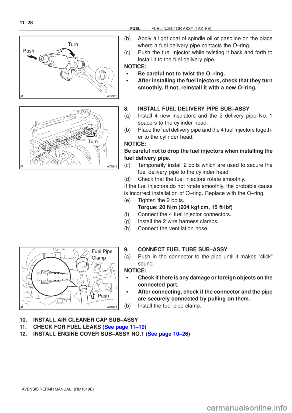
(b)Apply a light coat of spindle oil or gasoline on the place where a fuel delivery pipe contacts the O±ring.
(c)Push the fuel injector while twisting it back and forth to
install it to the fuel delivery pipe.
NOTICE:
�Be careful not to twist the O±ring.
�After installing the fuel injectors, check that they turn
smoothly. If not, reinstall it with a new O±ring.
8.INSTALL FUEL DELIVERY PIPE SUB±ASSY
(a)Install 4 new insulators and the 2 delivery pipe No. 1 spacers to the cylinder head.
(b)Place the fuel delivery pipe and the 4 fuel injectors togeth- er to the cylinder head.
NOTICE:
Be careful not to drop the fuel injectors when installing the
fuel delivery pipe.
(c)Temporarily install 2 bolts which are used to secure the fuel delivery pipe to the cylinder head.
(d)Check that the fuel injectors rotate smoothly.
If the fuel injectors do not rotate smoothly, the probable cause
is incorrect installation of O±ring. Replace with the O±ring.
(e)Tighten the 2 bolts. Torque: 20 N �m (204 kgf �cm, 15 ft �lbf)
(f)Connect the 4 fuel injector connectors.
(g)Install the 2 wire harness clamps.
(h)Connect the ventilation hose.
9.CONNECT FUEL TUBE SUB±ASSY
(a)Push in the connector to the pipe until it makes ºclickº sound.
NOTICE:
�Check if there is any damage or foreign objects on the
connected part.
�After connecting, check if the connector and the pipe
are securely connected by pulling on them.
(b)Install the fuel pipe clamp.
10.INSTALL AIR CLEANER CAP SUB±ASSY
11.CHECK FOR FUEL LEAKS (See page 11±19)
12.INSTALL ENGINE COVER SUB±ASSY NO.1 (See page 10±26)
Page 745 of 1690
110U2±01
A77915
±
FUEL FUEL PRESSURE PULSATION DAMPER
ASSY(1AZ±FE)11±29
AVENSIS REPAIR MANUAL (RM1018E)
FUEL PRESSURE PULSATION DAMPER ASSY(1AZ±FE)
REPLACEMENT
1.DISCHARGE FUEL SYSTEM PRESSURE (See page 11±15)
2.REMOVE ENGINE COVER SUB±ASSY NO.1 (See page 10±26)
3.REMOVE AIR CLEANER CAP SUB±ASSY (See page 10±26)
4.DISCONNECT FUEL TUBE SUB±ASSY (See page 11±26)
SST09268±21010
5.REMOVE FUEL PRESSURE PULSATION DAMPERASSY
(a)Remove the 2 bolts, and then remove the fuel pressure pulsation damper.
6.INSTALL FUEL PRESSURE PULSATION DAMPER ASSY
(a)Apply a light coat of spindle oil or gasoline to a new O±ring, and instal\
l it to the fuel pressure pulsation damper.
(b)Install the fuel pressure pulsation damper with the 2 bolts. Torque: 9.0 N �m (92 kgf �cm, 80 in. �lbf)
7.CONNECT FUEL TUBE SUB±ASSY (See page 11±26)
8. INSTALL AIR CLEANER CAP SUB±ASSY
9.CHECK FOR FUEL LEAKS (See page 11±19)
10.INSTALL ENGINE COVER SUB±ASSY NO.1 (See page 10±26)
Page 752 of 1690
±
FUEL FUEL PUMP ASSY(1AZ±FSE)
11±55
AVENSIS REPAIR MANUAL (RM1018E)
12.INSTALL ENGINE COVER BRACKET
(a)Install the engine cover bracket with the bolt.
Torque: 38 N �m (388 kgf �cm, 28 ft �lbf)
13.INSTALL AIR CLEANER CAP SUB±ASSY (See page 10±44)
14. CHECK FOR FUEL LEAKS
15. INSTALL ENGINE COVER SUB±ASSY NO.1 Torque: 7.0 N �m (71 kgf �cm, 62 in. �lbf)
16. INSTALL RADIATOR SUPPORT OPENING COVER
Page 754 of 1690
110U4±01
A78442
(a)
A78443
1
2
Tube Joint Clip
A60575
Nylon Tube
Fuel Tube Joint
O±ring Tube Joint Clip
Fuel Suction Plate
±
FUEL FUEL PUMP ASSY(GASOLINE)
11±85
AVENSIS REPAIR MANUAL (RM1018E)
REPLACEMENT
1.DISCHARGE FUEL SYSTEM PRESSURE
HINT:
�1ZZ±FE/3ZZ±FE: 11±1
�1AZ±FE: 11±15
�1AZ±FSE: 11±30
2.REMOVE REAR SEAT CUSHION ASSY (SEAT FIXED TYPE) (See page 72±32)
3. REMOVE REAR FLOOR SERVICE HOLE COVER
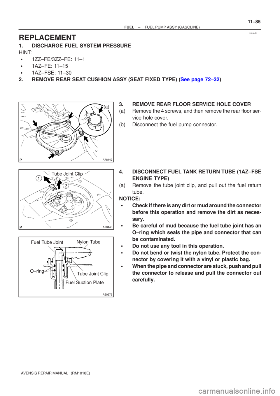
(a) Remove the 4 screws, and then remove the rear floor ser-vice hole cover.
(b) Disconnect the fuel pump connector.
4. DISCONNECT FUEL TANK RETURN TUBE (1AZ±FSE ENGINE TYPE)
(a) Remove the tube joint clip, and pull out the fuel return tube.
NOTICE:
�Check if there is any dirt or mud around the connector
before this operation and remove the dirt as neces-
sary.
�Be careful of mud because the fuel tube joint has an
O±ring which seals the pipe and connector that can
be contaminated.
�Do not use any tool in this operation.
�Do not bend or twist the nylon tube. Protect the con-
nector by covering it with a vinyl or plastic bag.
�When the pipe and connector are stuck, push and pull
the connector to release and pull the connector out
carefully.
Page 757 of 1690
A81614
Push
A81615
Push
A81616
Tube Joint Clip
Collar
2
1
11±88
±
FUEL FUEL PUMP ASSY(GASOLINE)
AVENSIS REPAIR MANUAL (RM1018E)
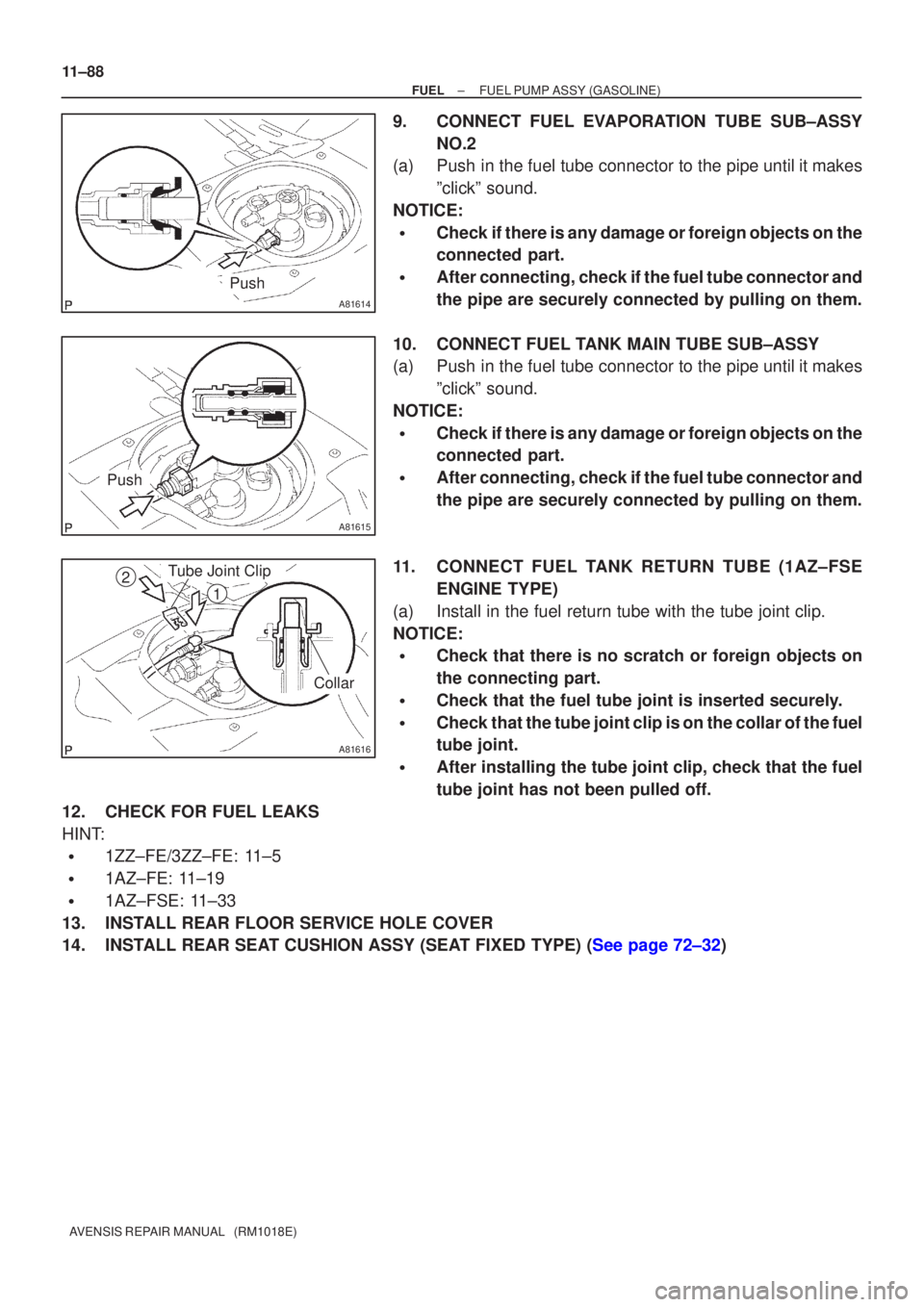
9.CONNECT FUEL EVAPORATION TUBE SUB±ASSY NO.2
(a)Push in the fuel tube connector to the pipe until it makes
ºclickº sound.
NOTICE:
�Check if there is any damage or foreign objects on the
connected part.
�After connecting, check if the fuel tube connector and
the pipe are securely connected by pulling on them.
10.CONNECT FUEL TANK MAIN TUBE SUB±ASSY
(a)Push in the fuel tube connector to the pipe until it makes ºclickº sound.
NOTICE:
�Check if there is any damage or foreign objects on the
connected part.
�After connecting, check if the fuel tube connector and
the pipe are securely connected by pulling on them.
11.C ONNECT FUEL TANK RETURN TUBE (1AZ±F SE
ENGINE TYPE)
(a)Install in the fuel return tube with the tube joint clip.
NOTICE:
�Check that there is no scratch or foreign objects on
the connecting part.
�Check that the fuel tube joint is inserted securely.
�Check that the tube joint clip is on the collar of the fuel
tube joint.
�After installing the tube joint clip, check that the fuel
tube joint has not been pulled off.
12.CHECK FOR FUEL LEAKS
HINT:
�1ZZ±FE/3ZZ±FE: 11±5
�1AZ±FE: 11±19
�1AZ±FSE: 11±33
13.INSTALL REAR FLOOR SERVICE HOLE COVER
14.INSTALL REAR SEAT CUSHION ASSY (SEAT FIXED TYPE) (See page 72±32)
Page 760 of 1690
110UX±01
Fuel Tube Connector
A50710
A60083
Fuel Pipe
Clamp No.1
AA
B12941
±
FUEL FUEL SYSTEM(1AZ±FE)
11±19
AVENSIS REPAIR MANUAL (RM1018E)
ON±VEHICLE INSPECTION
1.CHECK FUEL PRESSURE
(a)Discharge the pressure in the fuel system and take pre-
cautions for possible fuel spillage.(See page 11±15)
(b) Check that the battery voltage is above 12 V.
(c) Disconnect the negative (±) battery cable.
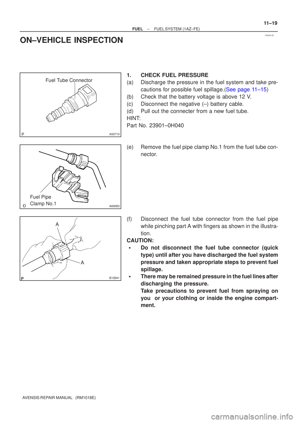
(d) Pull out the connecter from a new fuel tube.
HINT:
Part No. 23901±0H040
(e) Remove the fuel pipe clamp No.1 from the fuel tube con- nector.
(f) Disconnect the fuel tube connector from the fuel pipe while pinching part A with fingers as shown in the illustra-
tion.
CAUTION:
�Do not disconnect the fuel tube connector (quick
type) until after you have discharged the fuel system
pressure and taken appropriate steps to prevent fuel
spillage.
�There may be remained pressure in the fuel lines after
discharging the pressure.
Take precautions to prevent fuel from spraying on
you or your clothing or inside the engine compart-
ment.