Page 551 of 1690

14±293
AVENSIS REPAIR MANUAL (RM1018E)
87. REMOVE NOZZLE LEAKAGE PIPE NO.2
(a) Remove the check valve and bolt, and t")
A79194
A79148
SST
A79143
SST
± ENGINE MECHANICALPARTIAL ENGINE ASSY (1CD±FTV)
14±293
AVENSIS REPAIR MANUAL (RM1018E)
87. REMOVE NOZZLE LEAKAGE PIPE NO.2
(a) Remove the check valve and bolt, and then detach the
leakage pipe and the gasket.
88. REMOVE FUEL INLET PIPE SUB±ASSY
(a) Using SST, remove the fuel inlet pipe from the common
rail side.
SST 09023±12700
(b) Using SST, remove the fuel inlet pipe from the pump side.
SST 09023±12700
89. REMOVE INJECTION PIPE SUB±ASSY NO.1
(a) Remove the 2 nuts and 2 upper infection pipe clamps
from the intake manifold.
(b) Using SST, remove the injection pipe from the common
rail side.
SST 09023±12700
(c) Using SST, remove the injection pipe from the injector
side.
SST 09023±12700
(d) After removing the fuel pipe, to prevent dust or foreign ob-
jects being introduces, cover the common rail with vinyl
tape and protect the injector inlet with a vinyl or a plastic
bag.
(e) Remove the 2 lower injection pipe clamps from the intake
manifold.
90. REMOVE INJECTION PIPE SUB±ASSY NO.2
SST 09023±12700
HINT:
Perform the same procedures as injection pipe No. 1.
91. REMOVE INJECTION PIPE SUB±ASSY NO.3
SST 09023±12700
HINT:
Perform the same procedures as injection pipe No. 1.
92. REMOVE INJECTION PIPE SUB±ASSY NO.4
SST 09023±12700
HINT:
Perform the same procedures as injection pipe No. 1.
Page 554 of 1690

AVENSIS REPAIR MANUAL (RM1018E)
123.INSTALL POWER STEERING IDLE PULLEY BRACKET
(a)Install the")
A61175
AA
B
A79147
Fulcrum
Length
30 cm
SST
14±296
±
ENGINE MECHANICAL PARTIAL ENGINE ASSY(1CD±FTV)
AVENSIS REPAIR MANUAL (RM1018E)
123.INSTALL POWER STEERING IDLE PULLEY BRACKET
(a)Install the idle w/ bracket pulley with the 3 bolts.
Torque:
72 N�m (734 kgf �cm, 53 ft �lbf) for bolt A
39 N �m (398 kgf �cm, 29 ft �lbf) for bolt B
124.INSTALL COMMON RAIL ASSY (See page 11±78)
125. INSTALL INTAKE MANIFOLD INSULATOR NO.1 Torque: 5.0 N �m (51 kgf �cm, 44 in. �lbf)
126. INSTALL INJECTION PIPE SUB±ASSY NO.1
NOTICE:
�In case of having the injectors replaced, must replace
the injection pipes, too.
�When assembling the pipes, perform the operation
with the engine cold under room temperature.
(a) Install the 2 lower injection pipe clamps to the intake man-
ifold.
(b) Temporarily install the injection pipe.
(c) Using SST, tighten the nut of the injection pipe to the com- mon rail side.
SST 09023±12700
Torque:
42 N�m (428 kgf �cm, 31 ft �lbf) for a used pipe using SST
46 N �m (469 kgf �cm, 34 ft �lbf) for a used pipe not using
SST
31 N �m (316 kgf �cm, 23 ft �lbf) for a new pipe using SST
34 N �m (347 kgf �cm, 25 ft �lbf) for a new pipe not using
SST
HINT:
�Use a torque wrench with a fulcrum length of 30 cm
(11.81 in.)
�Check if the used pipe has deflection or is installed prop-
erly after injection pipe is reassembled. If there is deflec-
tion or if it can not be installed properly, replace the used
pipe with a new pipe.
Page 555 of 1690

14±297
AVENSIS REPAIR MANUAL (RM1018E)
(d) Using SST, tighten the nut of the injection pipe to the injec-
tor side.
SST 09023±12700
Torque:
42 N")
± ENGINE MECHANICALPARTIAL ENGINE ASSY (1CD±FTV)
14±297
AVENSIS REPAIR MANUAL (RM1018E)
(d) Using SST, tighten the nut of the injection pipe to the injec-
tor side.
SST 09023±12700
Torque:
42 N�m (428 kgf�cm, 31 ft�lbf) for a used pipe using SST
46 N�m (469 kgf�cm, 34 ft�lbf) for a used pipe not using
SST
31 N�m (316 kgf�cm, 23 ft�lbf) for a new pipe using SST
34 N�m (347 kgf�cm, 25 ft�lbf) for a new pipe not using
SST
HINT:
�Use a torque wrench with a fulcrum length of 30 cm
(11.81 in.)
�Check if the used pipe has deflection or is installed prop-
erly after injection pipe is reassembled. If there is deflec-
tion or if it can not be installed properly, replace the used
pipe with a new pipe.
(e) Install the 2 upper injection pipe clamps with the 2 nuts.
Torque: 5.0 N�m (51 kgf�cm, 44 in.�lbf)
127. INSTALL INJECTION PIPE SUB±ASSY NO.2
SST 09023±12700
HINT:
Perform the same procedures as injection pipe No. 1.
128. INSTALL INJECTION PIPE SUB±ASSY NO.3
SST 09023±12700
HINT:
Perform the same procedures as injection pipe No. 1.
129. INSTALL INJECTION PIPE SUB±ASSY NO.4
SST 09023±12700
HINT:
Perform the same procedures as injection pipe No. 1.
130. INSTALL FUEL INLET PIPE SUB±ASSY
NOTICE:
When assembling the pipe, perform the operation with the
engine cold under room temperature.
(a) Temporarily install the inlet pipe.
Page 556 of 1690

AVENSIS REPAIR MANUAL (RM1018E)
(b) Using SST, tighten the nut of the fuel inlet pipe to the com-")
A79149
Fulcrum
Length
30 cm
SST
A81587
14±298
± ENGINE MECHANICALPARTIAL ENGINE ASSY (1CD±FTV)
AVENSIS REPAIR MANUAL (RM1018E)
(b) Using SST, tighten the nut of the fuel inlet pipe to the com-
mon rail side.
SST 09023±12700
Torque:
42 N�m (428 kgf�cm, 31 ft�lbf) for a used pipe using SST
46 N�m (469 kgf�cm, 34 ft�lbf) for a used pipe not using
SST
31 N�m (316 kgf�cm, 23 ft�lbf) for a new pipe using SST
34 N�m (347 kgf�cm, 25 ft�lbf) for a new pipe not using
SST
HINT:
�Use a torque wrench with a fulcrum length of 30 cm
(11.81 in.)
�Check if the used pipe has deflection or is installed prop-
erly after inlet pipe is reassembled. If there is deflection
or if it can not be installed properly, replace the used pipe
with a new pipe.
(c) Using SST, tighten the nut of the fuel inlet pipe to the
pump side.
SST 09023±12700
Torque:
42 N�m (428 kgf�cm, 31 ft�lbf) for a used pipe using SST
46 N�m (469 kgf�cm, 34 ft�lbf) for a used pipe not using
SST
31 N�m (316 kgf�cm, 23 ft�lbf) for a new pipe using SST
34 N�m (347 kgf�cm, 25 ft�lbf) for a new pipe not using
SST
HINT:
�Use a torque wrench with a fulcrum length of 30 cm
(11.81 in.)
�Check if the used pipe has deflection or is installed prop-
erly after inlet pipe is reassembled. If there is deflection
or if it can not be installed properly, replace the used pipe
with a new pipe.
131. INSTALL NOZZLE LEAKAGE PIPE NO.2
(a) Install a new gasket and the leakage pipe with the check
valve.
Torque:
21 N�m (214 kgf�cm, 15 ft�lbf) for check valve
8.8 N�m (90 kgf�cm, 78 in.�lbf) for bolt
Page 558 of 1690

AVENSIS REPAIR MANUAL (RM1018E)
147. INSTALL OIL FILTER BRACKET SUB±ASSY
(a) Install a new gasket and oil filt")
A61186
SST
A57108
Adhesive
14±300
±
ENGINE MECHANICAL PARTIAL ENGINE ASSY (1CD±FTV)
AVENSIS REPAIR MANUAL (RM1018E)
147. INSTALL OIL FILTER BRACKET SUB±ASSY
(a) Install a new gasket and oil filter bracket with the bolt and 2 nuts. Torque: 34 N �m (347 kgf �cm, 25 ft �lbf)
148. INSTALL V±RIBBED BELT TENSIONER ASSY Torque: 31 N �m (316 kgf �cm, 23 ft �lbf)
149. INSTALL GENERATOR BRACKET NO.1 Torque: 37 N �m (377 kgf �cm, 27 ft �lbf)
150.INSTALL GENERATOR ASSY (See page 19±29)
151.SET NO. 1 CYLINDER TO TDC/COMPRESSION (See page 14±307) SST 09960±10010 (09962±01000, 09963±01000)
152.INSTALL TIMING BELT (See page 14±307)
153.CHECK VALVE TIMING (See page 14±307)
154.INSTALL TRANSVERSE ENGINE ENGINE MOUNTING BRACKET (See page 14±307)
155.INSTALL TIMING BELT GUIDE (See page 14±307)
156.INSTALL TIMING BELT NO.1 COVER (See page 14±307)
157.INSTALL TIMING BELT NO.2 COVER (See page 14±307)
158. INSTALL IDLER PULLEY SUB±ASSY Torque: 40 N �m (408 kgf �cm, 30 ft �lbf)
159.INSTALL CRANKSHAFT PULLEY (See page 14±307) SST 09213±54015 (90105±08076), 09330±00021
160.INSTALL GLOW PLUG ASSY (See page 19±33)
161. INSTALL ENGINE MOUNTING BRACKET RR Torque: 64 N �m (653 kgf �cm, 47 ft �lbf)
162. INSTALL ENGINE MOUNTING BRACKET FR Torque: 64 N �m (653 kgf �cm, 47 ft �lbf)
163. INSTALL DRIVE SHAFT BEARING BRACKET Torque: 64 N �m (653 kgf �cm, 47 ft �lbf)
164. INSTALL REAR END PLATE Torque: 8.4 N �m (86 kgf �cm, 74 in. �lbf)
165. INSTALL FLYWHEEL SUB±ASSY
(a) Using SST, hold the crankshaft. SST 09213±54015 (90105±08076), 09330±00021
(b) Clean the bolts and its bolt holes.
(c) Apply adhesive to 2 or 3 threads of the bolt end.
Adhesive: Part No. 08833±00070, THREE BOND 1324
or equivalent
Page 560 of 1690

AVENSIS REPAIR MANUAL (RM1018E)
(e)Install the front suspension crossmember with the 2 bolts and 2 nuts.
Tor")
A59792
BB
AA
A59793
AA
BBBBB
B
14±302
±
ENGINE MECHANICAL PARTIAL ENGINE ASSY(1CD±FTV)
AVENSIS REPAIR MANUAL (RM1018E)
(e)Install the front suspension crossmember with the 2 bolts and 2 nuts.
Torque:
45 N�m (459 kgf �cm, 33 ft �lbf) for bolt A
133 N �m (1,356 kgf �cm, 98 ft �lbf) for nut B
(f)Install the front suspension member brace LH and RH with the 8 bolts.
Torque:
133 N �m (1,356 kgf �cm, 98 ft �lbf) for bolt A
80 N �m (816 kgf �cm, 59 ft �lbf) for nut B
NOTICE:
After installing the crossmember, check that the position-
ing holes on the crossmember and the vehicle are aligned.
171.INSTALL FRONT DRIVE SHAFT ASSY LH (See page 30±6)
HINT:
Perform the same procedure as above on the opposite side.
172.INSTALL FRONT SUSPENSION ARM SUB±ASSY LOWER NO.1 LH (See page 26±21)
HINT:
Perform the same procedure as above on the opposite side.
173.INSTALL STEERING INTERMEDIATE SHAFT ASSY NO.2 (See page 51±36)
174.INSTALL FRONT STABILIZER LINK ASSY LH (See page 26±26)
HINT:
Perform the same procedure as above on the opposite side. SST 99999±70037
175.INSTALL TIE ROD END SUB±ASSY LH (See page 30±6)
HINT:
Perform the same procedure as above on the opposite side.
176.INSTALL FRONT AXLE HUB LH NUT (See page 30±6)
HINT:
Perform the same procedure as above on the opposite side.
177. INSTALL RETURN TUBE SUB±ASSY Torque: 8.0 N �m (82 kgf �cm, 71 in. �lbf)
178.INSTALL EXHAUST PIPE ASSY FRONT (See page 15±10)
179.INSTALL FLOOR PANEL BRACE FRONT (See page 15±10)
180. INSTALL COMPRESSOR AND MAGNETIC CLUTCH (W/ AIR CONDITIONING) (See page 55±86)
181.ADJUST V (COOLER COMPRESSOR TO CRANKSHAFT PULLEY) BELT NO.1 (See page 14±269 )
182.INSTALL CLUTCH RELEASE CYLINDER ASSY (See page 42±17)
183.INSTALL CLUTCH ACCUMULATOR ASSY (See page 42±17) SST 09023±00100
Page 562 of 1690
14±304
±
ENGINE MECHANICAL PARTIAL ENGINE ASSY (1CD±FTV)
AVENSIS REPAIR MANUAL (RM1018E)
191. INSTALL AIR CLEANER ASSY Torque: 7.0 N �m (71 kgf �cm, 62 in. �lbf)
192. INSTALL ENGINE COVER NO.1
Torque: 8.0 N �m (82 kgf �cm, 71 in. �lbf)
193.BLEED CLUTCH PIPE LINE (See page 42±17)
194. INSTALL FRONT WHEELS Torque: 103 N �m (1,050 kgf �cm, 76 ft �lbf)
195. ADD MANUAL TRANSAXLE OIL
196. ADD ENGINE OIL
197.ADD ENGINE COOLANT (See page 16±44)
198. CHECK CLUTCH FLUID LEAKAGE
199. CHECK FLUID LEVEL IN RESERVOIR
200. CHECK BRAKE FLUID LEAKAGE
201. CHECK FOR ENGINE OIL LEAKS
202.CHECK FOR FUEL LEAKS (See page 11±60)
203.CHECK FOR ENGINE COOLANT LEAKS (See page 16±44)
204. CHECK FOR EXHAUST GAS LEAKS
205.INSPECT AND ADJUST FRONT WHEEL ALIGNMENT (See page 26±6)
206.INSPECT ENGINE IDLE SPEED (See page 14±266)
207.CHECK ABS SPEED SENSOR SIGNAL (See page 05±756)
Page 585 of 1690
A76713
A62838SST
A62205
1
5
3
82
6
4
7
A62206
90�
A62838SST
± ENGINE MECHANICALPARTIAL ENGINE ASSY (1ZZ±FE/3ZZ±FE)
14±41
AVENSIS REPAIR MANUAL (RM1018E)
(b) Install the engine wire with the 2 nuts.
Torque: 9.0 N�m (92 kgf�cm, 80 in.�lbf)
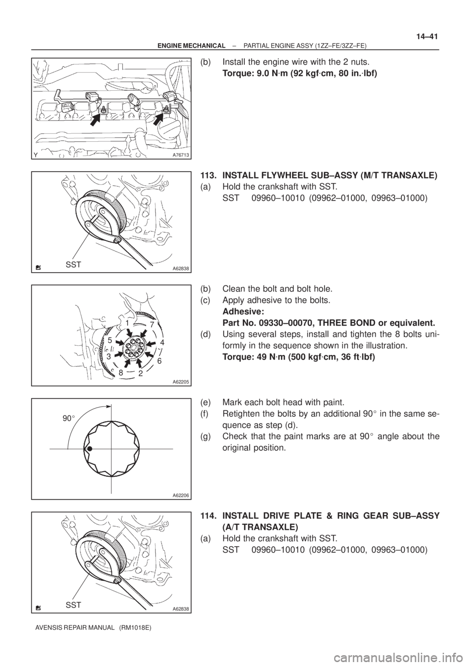
113. INSTALL FLYWHEEL SUB±ASSY (M/T TRANSAXLE)
(a) Hold the crankshaft with SST.
SST 09960±10010 (09962±01000, 09963±01000)
(b) Clean the bolt and bolt hole.
(c) Apply adhesive to the bolts.
Adhesive:
Part No. 09330±00070, THREE BOND or equivalent.
(d) Using several steps, install and tighten the 8 bolts uni-
formly in the sequence shown in the illustration.
Torque: 49 N�m (500 kgf�cm, 36 ft�lbf)
(e) Mark each bolt head with paint.
(f) Retighten the bolts by an additional 90� in the same se-
quence as step (d).
(g) Check that the paint marks are at 90� angle about the
original position.
114. INSTALL DRIVE PLATE & RING GEAR SUB±ASSY
(A/T TRANSAXLE)
(a) Hold the crankshaft with SST.
SST 09960±10010 (09962±01000, 09963±01000)