Page 913 of 1690
I35337
I35336
I35339
I35340
55±94
±
HEATER & AIR CONDITIONER W/RECEIVER CONDENSER ASSY
AVENSIS REPAIR MANUAL (RM1018E)
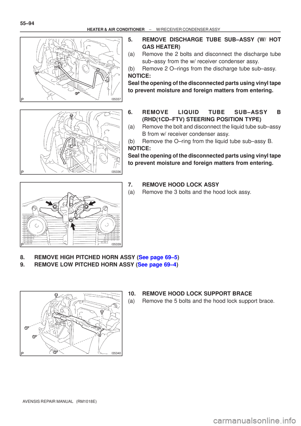
5. REMOVE DISCHARGE TUBE SUB±ASSY (W/ HOT GAS HEATER)
(a) Remove the 2 bolts and disconnect the discharge tube
sub±assy from the w/ receiver condenser assy.
(b) Remove 2 O±rings from the discharge tube sub±assy.
NOTICE:
Seal the opening of the disconnected parts using vinyl tape
to prevent moisture and foreign matters from entering.
6. REMOVE LIQUID TUBE SUB±ASSY B (RHD(1CD±FTV) STEERING POSITION TYPE)
(a) Remove the bolt and disconnect the liquid tube sub±assy B from w/ receiver condenser assy.
(b) Remove the O±ring from the liquid tube sub±assy B.
NOTICE:
Seal the opening of the disconnected parts using vinyl tape
to prevent moisture and foreign matters from entering.
7. REMOVE HOOD LOCK ASSY
(a) Remove the 3 bolts and the hood lock assy.
8.REMOVE HIGH PITCHED HORN ASSY (See page 69±5)
9.REMOVE LOW PITCHED HORN ASSY (See page 69±4) 10. REMOVE HOOD LOCK SUPPORT BRACE
(a) Remove the 5 bolts and the hood lock support brace.
Page 916 of 1690
I35344
I35343
I35342
I35336
± HEATER & AIR CONDITIONERW/RECEIVER CONDENSER ASSY
55±97
AVENSIS REPAIR MANUAL (RM1018E)
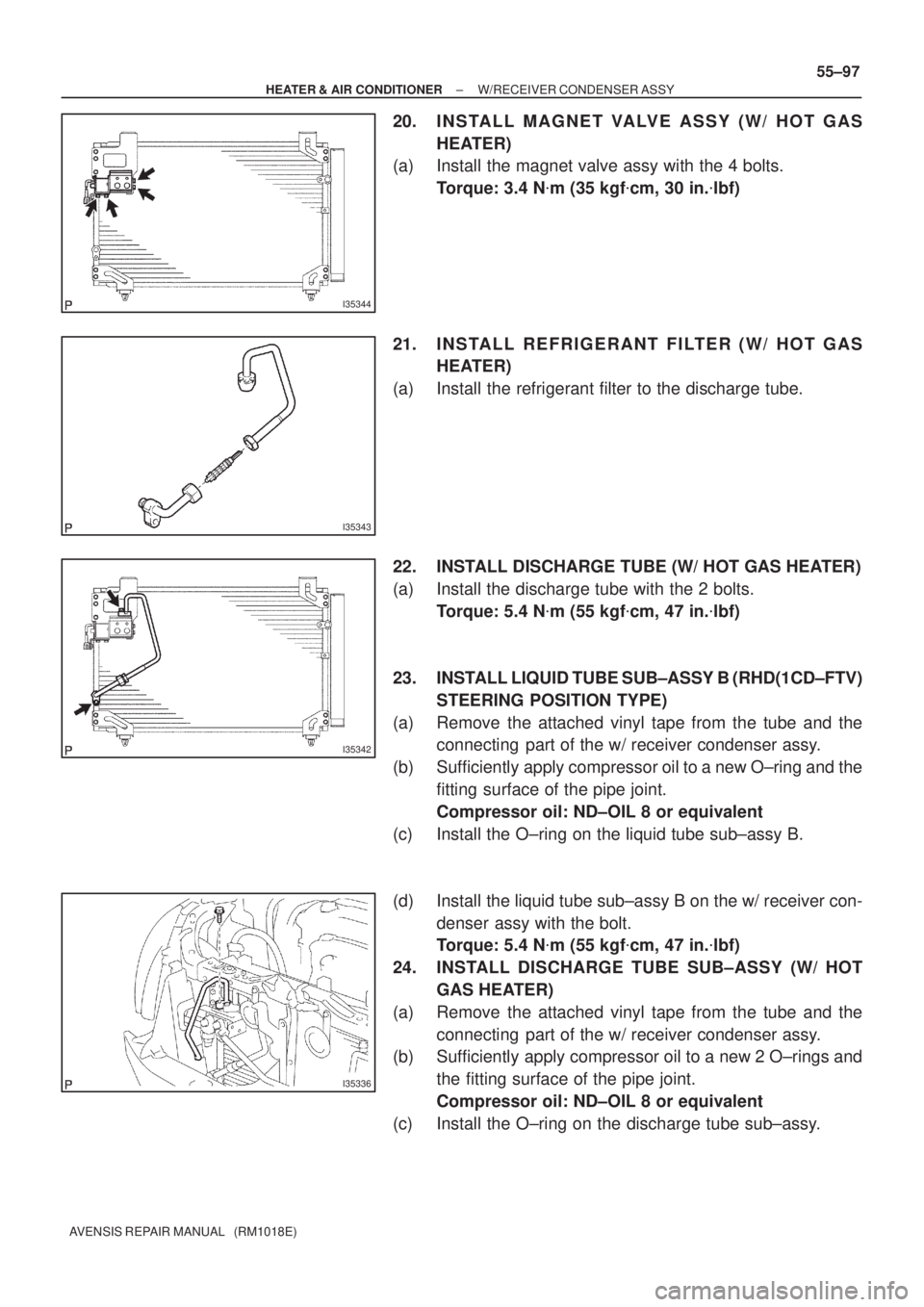
20. I N S TA L L M A G N E T VA LV E A S S Y ( W / H O T G A S
HEATER)
(a) Install the magnet valve assy with the 4 bolts.
Torque: 3.4 N�m (35 kgf�cm, 30 in.�lbf)
21. INSTALL REFRIGERANT FILTER (W/ HOT GAS
HEATER)
(a) Install the refrigerant filter to the discharge tube.
22. INSTALL DISCHARGE TUBE (W/ HOT GAS HEATER)
(a) Install the discharge tube with the 2 bolts.
Torque: 5.4 N�m (55 kgf�cm, 47 in.�lbf)
23. INSTALL LIQUID TUBE SUB±ASSY B (RHD(1CD±FTV)
STEERING POSITION TYPE)
(a) Remove the attached vinyl tape from the tube and the
connecting part of the w/ receiver condenser assy.
(b) Sufficiently apply compressor oil to a new O±ring and the
fitting surface of the pipe joint.
Compressor oil: ND±OIL 8 or equivalent
(c) Install the O±ring on the liquid tube sub±assy B.
(d) Install the liquid tube sub±assy B on the w/ receiver con-
denser assy with the bolt.
Torque: 5.4 N�m (55 kgf�cm, 47 in.�lbf)
24. INSTALL DISCHARGE TUBE SUB±ASSY (W/ HOT
GAS HEATER)
(a) Remove the attached vinyl tape from the tube and the
connecting part of the w/ receiver condenser assy.
(b) Sufficiently apply compressor oil to a new 2 O±rings and
the fitting surface of the pipe joint.
Compressor oil: ND±OIL 8 or equivalent
(c) Install the O±ring on the discharge tube sub±assy.
Page 923 of 1690
I35337
I35336
I35339
I35340
55±94
±
HEATER & AIR CONDITIONER W/RECEIVER CONDENSER ASSY
AVENSIS REPAIR MANUAL (RM1018E)
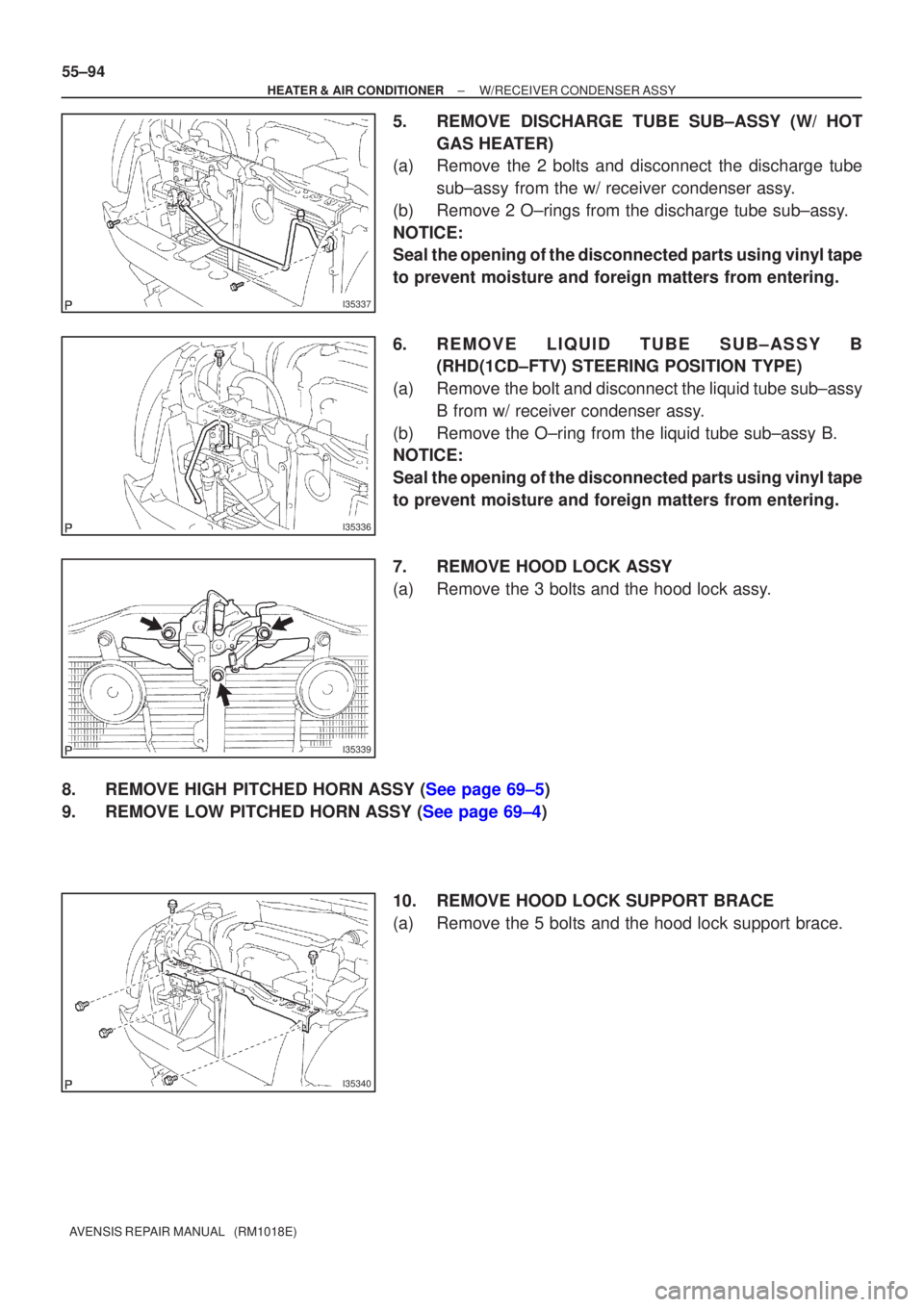
5. REMOVE DISCHARGE TUBE SUB±ASSY (W/ HOT GAS HEATER)
(a) Remove the 2 bolts and disconnect the discharge tube
sub±assy from the w/ receiver condenser assy.
(b) Remove 2 O±rings from the discharge tube sub±assy.
NOTICE:
Seal the opening of the disconnected parts using vinyl tape
to prevent moisture and foreign matters from entering.
6. REMOVE LIQUID TUBE SUB±ASSY B (RHD(1CD±FTV) STEERING POSITION TYPE)
(a) Remove the bolt and disconnect the liquid tube sub±assy B from w/ receiver condenser assy.
(b) Remove the O±ring from the liquid tube sub±assy B.
NOTICE:
Seal the opening of the disconnected parts using vinyl tape
to prevent moisture and foreign matters from entering.
7. REMOVE HOOD LOCK ASSY
(a) Remove the 3 bolts and the hood lock assy.
8.REMOVE HIGH PITCHED HORN ASSY (See page 69±5)
9.REMOVE LOW PITCHED HORN ASSY (See page 69±4) 10. REMOVE HOOD LOCK SUPPORT BRACE
(a) Remove the 5 bolts and the hood lock support brace.
Page 926 of 1690
I35344
I35343
I35342
I35336
± HEATER & AIR CONDITIONERW/RECEIVER CONDENSER ASSY
55±97
AVENSIS REPAIR MANUAL (RM1018E)
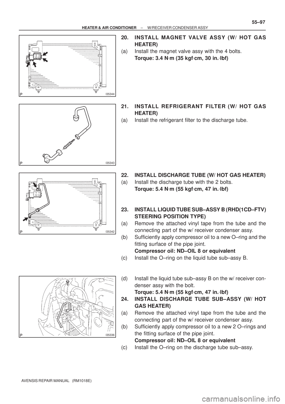
20. I N S TA L L M A G N E T VA LV E A S S Y ( W / H O T G A S
HEATER)
(a) Install the magnet valve assy with the 4 bolts.
Torque: 3.4 N�m (35 kgf�cm, 30 in.�lbf)
21. INSTALL REFRIGERANT FILTER (W/ HOT GAS
HEATER)
(a) Install the refrigerant filter to the discharge tube.
22. INSTALL DISCHARGE TUBE (W/ HOT GAS HEATER)
(a) Install the discharge tube with the 2 bolts.
Torque: 5.4 N�m (55 kgf�cm, 47 in.�lbf)
23. INSTALL LIQUID TUBE SUB±ASSY B (RHD(1CD±FTV)
STEERING POSITION TYPE)
(a) Remove the attached vinyl tape from the tube and the
connecting part of the w/ receiver condenser assy.
(b) Sufficiently apply compressor oil to a new O±ring and the
fitting surface of the pipe joint.
Compressor oil: ND±OIL 8 or equivalent
(c) Install the O±ring on the liquid tube sub±assy B.
(d) Install the liquid tube sub±assy B on the w/ receiver con-
denser assy with the bolt.
Torque: 5.4 N�m (55 kgf�cm, 47 in.�lbf)
24. INSTALL DISCHARGE TUBE SUB±ASSY (W/ HOT
GAS HEATER)
(a) Remove the attached vinyl tape from the tube and the
connecting part of the w/ receiver condenser assy.
(b) Sufficiently apply compressor oil to a new 2 O±rings and
the fitting surface of the pipe joint.
Compressor oil: ND±OIL 8 or equivalent
(c) Install the O±ring on the discharge tube sub±assy.
Page 952 of 1690
710G0±01
B660342 Clips
B660407 Claws
±
INSTRUMENT PANEL/METER COMBINATION METER ASSY
71±21
AVENSIS REPAIR MANUAL (RM1018E)
COMBINATION METER ASSY
OVERHAUL
1.REMOVE STEERING COLUMN COVER LWR (See page 50±9)
2.REMOVE STEERING COLUMN COVER W/INSTRUMENT CLUSTER FINISH PANEL ASSY
(See page 50±9)
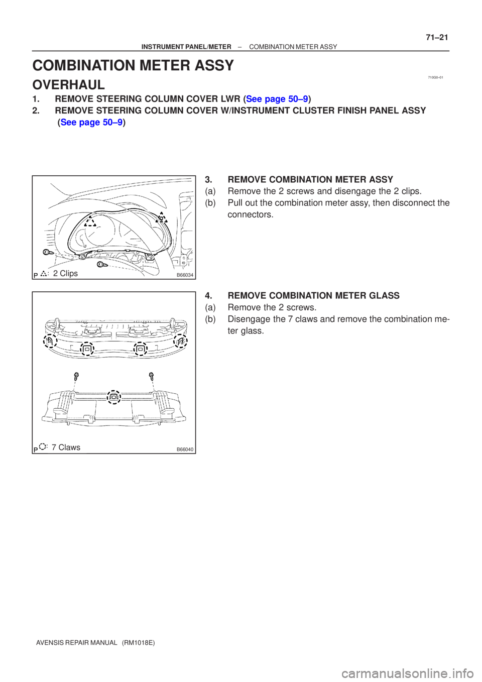
3. REMOVE COMBINATION METER ASSY
(a) Remove the 2 screws and disengage the 2 clips.
(b) Pull out the combination meter assy, then disconnect theconnectors.
4. REMOVE COMBINATION METER GLASS
(a) Remove the 2 screws.
(b) Disengage the 7 claws and remove the combination me- ter glass.
Page 953 of 1690
710G2±01
B66037
Front Pillar Garnish LH
Front Pillar Garnish RH
Instrument Panel Register
Assy No.2
Instrument Panel Register
Assy No.1
Steering Column Cover
w/ Instrument Cluster Finish Panel AssyCombination Meter AssyGlove Compartment
Door AssyGlove Compartment
Door Stopper Sub±assy
w/ Multi±Display: w/ Box: w/ Navi:
Instrument Panel Register Assy CTR
Instrument Cluster Finish
Panel Garnish No.2 Steering
Column Cover LWR
Instrument Cluster Finish
Panel Garnish No.1
Combination Meter Glass
N´m (kgf´cm, ft´lbf) : Specified torque
A
G
H
H
HHHHHH
20 (200, 14)
± INSTRUMENT PANEL/METERINSTRUMENT PANEL/METER
71±7
AVENSIS REPAIR MANUAL (RM1018E)
INSTRUMENT PANEL/METER
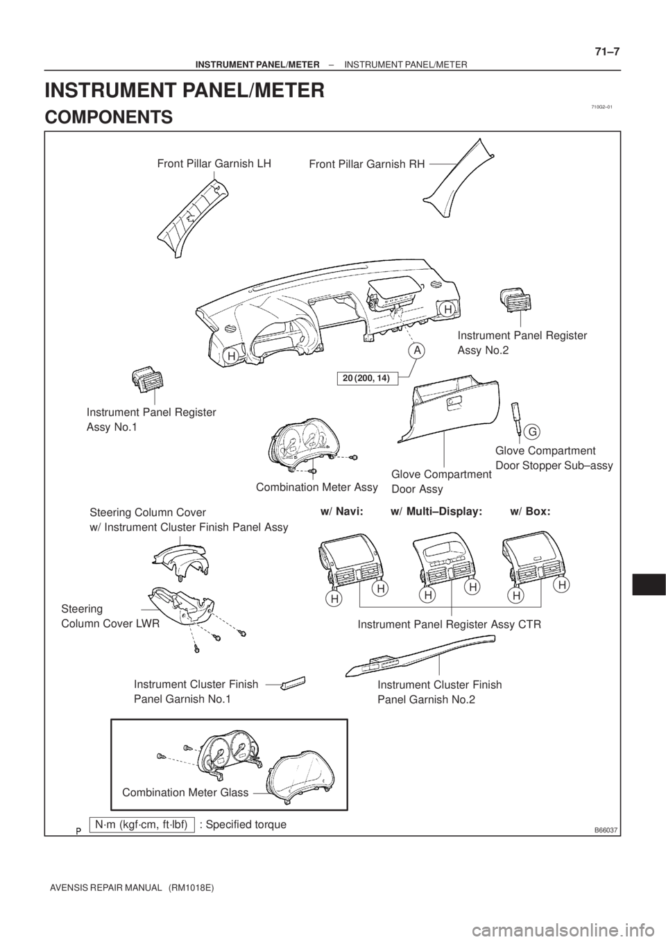
COMPONENTS
Page 954 of 1690
B66038
Heater to Register Duct No.2
Instrument Panel Lower Assy
Cowl Side Trim
Board RH
Front Door
Scuff Plate
RH
Floor Shift
Shift Lever
Knob Sub±assy Console Panel
Sub±assy Upper
Console Panel Sub±assy Lower
Console Box Assy RR Front Door
Scuff Plate LHCowl Side Trim
Board LH
Instrument Panel Airbag Assy
Console Rear End
Panel
Radio Receiver
Assembly w/ Bracket
Windshield
Wiper Switch Assy
Instrument Panel
Hole CoverHead lamp
Dimmer Switch Assy
Instrument Panel Under
Cover Sub±assy No.2
Horn Button Assy Steering Wheel Assy
Instrument Panel Under Cover
Sub±assy No.1
H
N´m (kgf´cm, ft´lbf) : Specified torqueM/T Transaxle: A/T Transaxle:
A/T Only:
M/T Only:
50 (510, 37)
8.8 (90, 78 in.´lbf)
orEF
D
B
Bor
EF
I
or
EF
or
EF
H
HH
H
H
HH
H
H
CC
CC
H
HConsole Panel
Sub±assy Upper
18 (184, 13)
18 (184, 13)
71±8
± INSTRUMENT PANEL/METERINSTRUMENT PANEL/METER
AVENSIS REPAIR MANUAL (RM1018E)
Page 982 of 1690
010B6±13
±
INTRODUCTION HOW TO TROUBLESHOOT ECU CONTROLLED
SYSTEMS01±21
AVENSIS REPAIR MANUAL (RM1018E)
HOW TO TROUBLESHOOT ECU CONTROLLED SYSTEMS
GENERAL INFORMATION
There are many ECU controlled systems used in the AVENSIS. In general, ECU controlled system are con-
sidered to be very intricate and require a high level of technical knowledge an\
d expert skill to troubleshoot.
The fact is, however, that if you proceed by inspecting the circuits one by one, troubleshoo\
ting of these sys-
tems is not complex. If you have adequate understanding of the system and ba\
sic knowledge of electricity,
the problem can be accurately diagnosed and fixed. This manual is design\
ed based on the above principle
to help service technicians perform accurate and effective troubleshooting, and is compiled for the following
major ECU controlled systems:
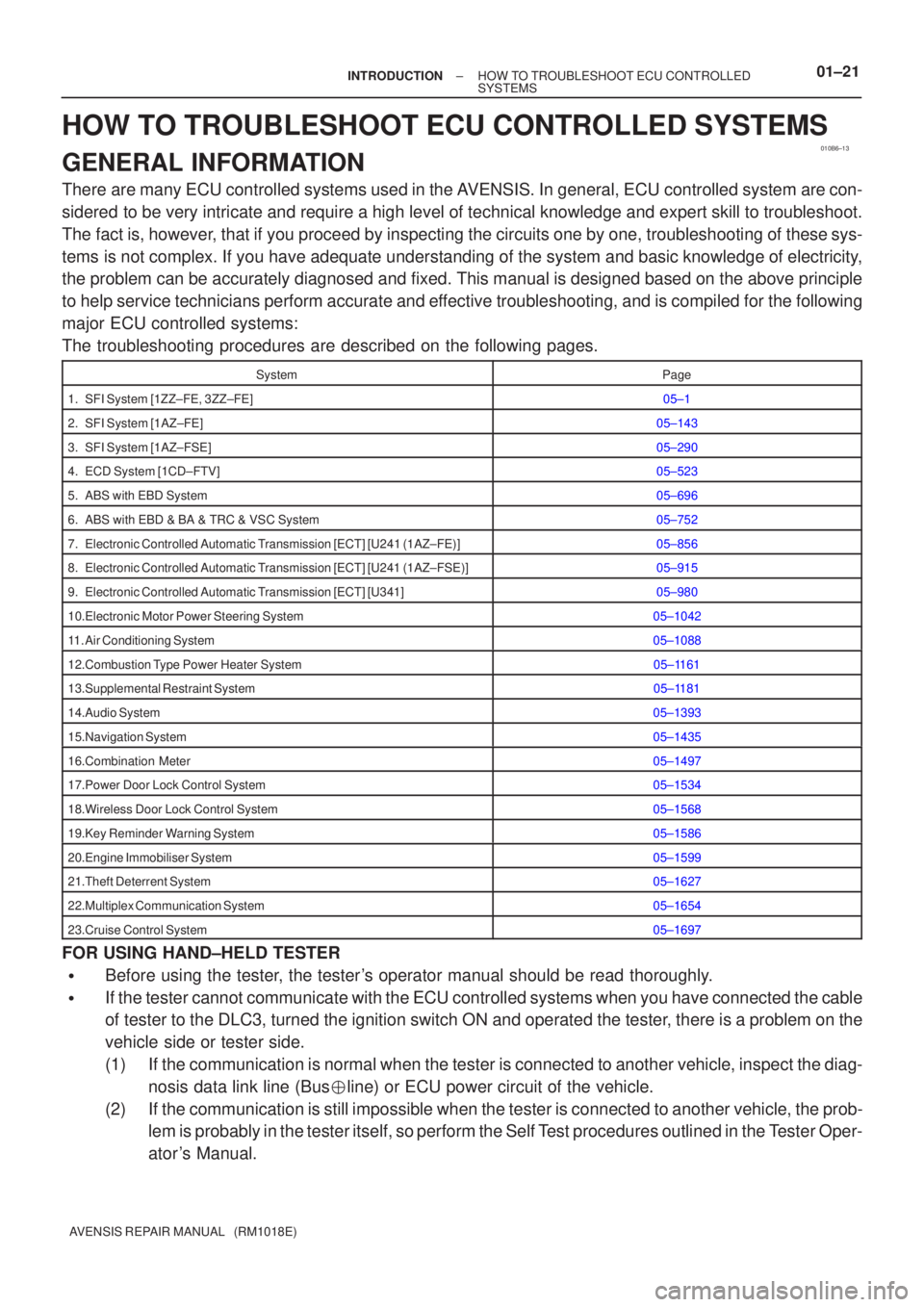
The troubleshooting procedures are described on the following pages.
SystemPage
1. SFI System [1ZZ±FE, 3ZZ±FE]05±1
2. SFI System [1AZ±FE]05±143
3. SFI System [1AZ±FSE]05±290
4. ECD System [1CD±FTV]05±523
5. ABS with EBD System05±696
6. ABS with EBD & BA & TRC & VSC System05±752
7. Electronic Controlled Automatic Transmission [ECT] [U241 (1AZ±FE)]05±856
8. Electronic Controlled Automatic Transmission [ECT] [U241 (1AZ±FSE)]05±915
9. Electronic Controlled Automatic Transmission [ECT] [U341]05±980
10.Electronic Motor Power Steering System05±1042
11. Air Conditioning System05±1088
12.Combustion Type Power Heater System05±1161
13.Supplemental Restraint System05±1181
14.Audio System05±1393
15.Navigation System05±1435
16.Combination Meter05±1497
17.Power Door Lock Control System05±1534
18.Wireless Door Lock Control System05±1568
19.Key Reminder Warning System05±1586
20.Engine Immobiliser System05±1599
21.Theft Deterrent System05±1627
22.Multiplex Communication System05±1654
23.Cruise Control System05±1697
FOR USING HAND±HELD TESTER
�Before using the tester, the tester's operator manual should be read thoroughly.
�If the tester cannot communicate with the ECU controlled systems when you \
have connected the cable
of tester to the DLC3, turned the ignition switch ON and operated the test\
er, there is a problem on the
vehicle side or tester side.
(1) If the communication is normal when the tester is connected to another veh\
icle, inspect the diag-
nosis data link line (Bus �line) or ECU power circuit of the vehicle.
(2) If the communication is still impossible when the tester is connected to a\
nother vehicle, the prob- lem is probably in the tester itself, so perform the Self Test procedures outlined in the Tester Oper-
ator 's Manual.