Page 712 of 1690
2600K±06
±
FRONT SUSPENSION FRONT SUSPENSION SYSTEM
26±1
AVENSIS REPAIR MANUAL (RM1018E)
FRONT SUSPENSION SYSTEM
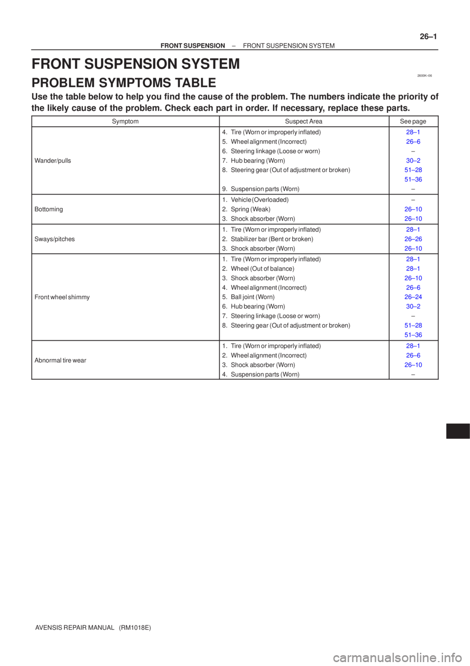
PROBLEM SYMPTOMS TABLE
Use the table below to help you find the cause of the problem. The numbers \
indicate the priority of
the likely cause of the problem. Check each part in order. If necessary, replace these parts.
SymptomSuspect AreaSee page
Wander/pulls
4. Tire (Worn or improperly inflated)
5. Wheel alignment (Incorrect)
6. Steering linkage (Loose or worn)
7. Hub bearing (Worn)
8. Steering gear (Out of adjustment or broken)
9. Suspension parts (Worn)28±1
26±6
±
30±2
51±28
51±36
±
Bottoming
1. Vehicle (Overloaded)
2. Spring (Weak)
3. Shock absorber (Worn)±
26±10
26±10
Sways/pitches
1. Tire (Worn or improperly inflated)
2. Stabilizer bar (Bent or broken)
3. Shock absorber (Worn)28±1
26±26
26±10
Front wheel shimmy
1. Tire (Worn or improperly inflated)
2. Wheel (Out of balance)
3. Shock absorber (Worn)
4. Wheel alignment (Incorrect)
5. Ball joint (Worn)
6. Hub bearing (Worn)
7. Steering linkage (Loose or worn)
8. Steering gear (Out of adjustment or broken)28±1
28±1
26±10 26±6
26±24
30±2 ±
51±28
51±36
Abnormal tire wear
1. Tire (Worn or improperly inflated)
2. Wheel alignment (Incorrect)
3. Shock absorber (Worn)
4. Suspension parts (Worn)28±1
26±6
26±10 ±
Page 714 of 1690
SA0028
AB
FrontA B
A: Inside
B: Outside
Z03382
Alignment
TesterGauge
± FRONT SUSPENSIONFRONT WHEEL ALIGNMENT
26±7
AVENSIS REPAIR MANUAL (RM1018E)
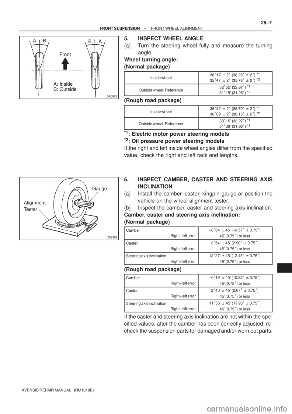
5. INSPECT WHEEL ANGLE
(a) Turn the steering wheel fully and measure the turning
angle.
Wheel turning angle:
(Normal package)
Inside wheel
�17' � 2� �
��
� � �����
�47' � 2� �
��
� � �����
Outside wheel: Reference32�52' � ��
�����
31��5' � ���
����
(Rough road package)
Inside wheel
�42' � 2� �
���� � �����
��09' � 2� � ���
� � �����
Outside wheel: Reference33�16' � �������
31�38' � ��� ����
*1: Electric motor power steering models
*2: Oil pressure power steering models
If the right and left inside wheel angles differ from the specified
value, check the right and left rack end lengths.
6. INSPECT CAMBER, CASTER AND STEERING AXIS
INCLINATION
(a) Install the camber±caster±kingpin gauge or position the
vehicle on the wheel alignment tester.
(b) Inspect the camber, caster and steering axis inclination.
Camber, caster and steering axis inclination:
(Normal package)
Camber
Right±left error±0�34' � 45' (±0.57� � 0.75�)
45' (0.75�) or less
Caster
Right±left error��54' � 45' (2.90� � 0.75�)
45' (0.75�) or less
Steering axis inclination
Right±left error���27' � 45' (12.45� � 0.75�)
45' (0.75�) or less
(Rough road package)
Camber
Right±left error±0�19' � 45' (±0.32� � 0.75�)
45' (0.75�) or less
Caster
Right±left error��40' � 45' (2.67� � 0.75�)
45' (0.75�) or less
Steering axis inclination
Right±left error���56' � 45' (11.93� � 0.75�)
45' (0.75�) or less
If the caster and steering axis inclination are not within the spe-
cified values, after the camber has been correctly adjusted, re-
check the suspension parts for damaged and/or worn out parts.
Page 715 of 1690
F13683
26±8
± FRONT SUSPENSIONFRONT WHEEL ALIGNMENT
AVENSIS REPAIR MANUAL (RM1018E)
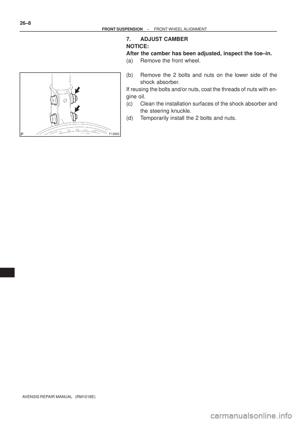
7. ADJUST CAMBER
NOTICE:
After the camber has been adjusted, inspect the toe±in.
(a) Remove the front wheel.
(b) Remove the 2 bolts and nuts on the lower side of the
shock absorber.
If reusing the bolts and/or nuts, coat the threads of nuts with en-
gine oil.
(c) Clean the installation surfaces of the shock absorber and
the steering knuckle.
(d) Temporarily install the 2 bolts and nuts.
Page 719 of 1690
2600P±03
F44620
G21679
26±26
±
FRONT SUSPENSION STABILIZER BAR FRONT
AVENSIS REPAIR MANUAL (RM1018E)
STABILIZER BAR FRONT
REPLACEMENT
HINT:
COMPONENTS: See page 26±2
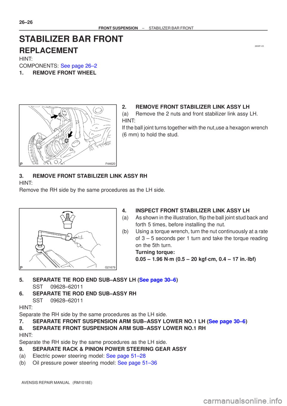
1. REMOVE FRONT WHEEL 2. REMOVE FRONT STABILIZER LINK ASSY LH
(a) Remove the 2 nuts and front stabilizer link assy LH.
HINT:
If the ball joint turns together with the nut,use a hexagon wrench
(6 mm) to hold the stud.
3. REMOVE FRONT STABILIZER LINK ASSY RH
HINT:
Remove the RH side by the same procedures as the LH side. 4. INSPECT FRONT STABILIZER LINK ASSY LH
(a) As shown in the illustration, flip the ball joint stud back andforth 5 times, before installing the nut.
(b) Using a torque wrench, turn the nut continuously at a rate
of 3 ± 5 seconds per 1 turn and take the torque reading
on the 5th turn.
Turning torque:
0.05 ± 1.96 N´m (0.5 ± 20 kgf´cm, 0.4 ± 17 in.´lbf)
5.SEPARATE TIE ROD END SUB±ASSY LH (See page 30±6) SST 09628±62011
6. SEPARATE TIE ROD END SUB±ASSY RH
SST 09628±62011
HINT:
Separate the RH side by the same procedures as the LH side.
7.SEPARATE FRONT SUSPENSION ARM SUB±ASSY LOWER NO.1 LH (See page 30±6)
8. SEPARATE FRONT SUSPENSION ARM SUB±ASSY LOWER NO.1 RH
HINT:
Separate the RH side by the same procedures as the LH side.
9. SEPARATE RACK & PINION POWER STEERING GEAR ASSY
(a)Electric power steering model: See page 51±28
(b)Oil pressure power steering model: See page 51±36
Page 721 of 1690
F45155
A
B
F44620
26±28
±
FRONT SUSPENSION STABILIZER BAR FRONT
AVENSIS REPAIR MANUAL (RM1018E)
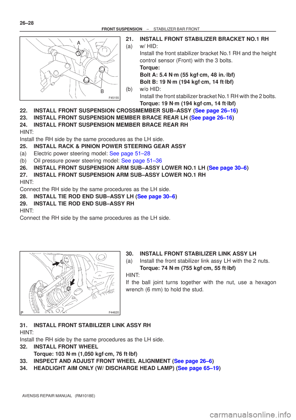
21. INSTALL FRONT STABILIZER BRACKET NO.1 RH
(a) w/ HID: Install the front stabilizer bracket No.1 RH and the height
control sensor (Front) with the 3 bolts.
Torque:
Bolt A: 5.4 N �m (55 kgf �cm, 48 in. �lbf)
Bolt B: 19 N �m (194 kgf �cm, 14 ft �lbf)
(b) w/o HID: Install the front stabilizer bracket No.1 RH with the 2 bolts.
Torque: 19 N �m (194 kgf �cm, 14 ft �lbf)
22.INSTALL FRONT SUSPENSION CROSSMEMBER SUB±ASSY (See page 26±16)
23.INSTALL FRONT SUSPENSION MEMBER BRACE REAR LH (See page 26±16)
24. INSTALL FRONT SUSPENSION MEMBER BRACE REAR RH
HINT:
Install the RH side by the same procedures as the LH side.
25. INSTALL RACK & PINION POWER STEERING GEAR ASSY
(a)Electric power steering model: See page 51±28
(b)Oil pressure power steering model: See page 51±36
26.INSTALL FRONT SUSPENSION ARM SUB±ASSY LOWER NO.1 LH (See page 30±6)
27. INSTALL FRONT SUSPENSION ARM SUB±ASSY LOWER NO.1 RH
HINT:
Connect the RH side by the same procedures as the LH side.
28.INSTALL TIE ROD END SUB±ASSY LH (See page 30±6)
29. INSTALL TIE ROD END SUB±ASSY RH
HINT:
Connect the RH side by the same procedures as the LH side.
30. INSTALL FRONT STABILIZER LINK ASSY LH
(a) Install the front stabilizer link assy LH with the 2 nuts.Torque: 74 N �m (755 kgf �cm, 55 ft �lbf)
HINT:
If the ball joint turns together with the nut, use a hexagon
wrench (6 mm) to hold the stud.
31. INSTALL FRONT STABILIZER LINK ASSY RH
HINT:
Install the RH side by the same procedures as the LH side.
32. INSTALL FRONT WHEEL Torque: 103 N �m (1,050 kgf �cm, 76 ft �lbf)
33.INSPECT AND ADJUST FRONT WHEEL ALIGNMENT (See page 26±6)
34.HEADLIGHT AIM ONLY (W/ DISCHARGE HEAD LAMP) (See page 65±19)
Page 807 of 1690
110U9±01
A79435
Air Cleaner Cap w/ Hose
Air Cleaner Element
Air Cleaner Case
7.0 (71, 62 in.�lbf)
N´m (kgf´cm, ft´lbf)
: Specified torque
Radiator Hose Outlet
Clip
Engine Room Cover Side
Clip
Retainer
Radiator Support
Opening Cover
8.0 (82, 71 in.�lbf)
5.0 (51, 44 in.�lbf)
V (Cooler Compressor
to Crankshaft Pulley)
Belt No. 1
Injector Driver
72 (734, 53)
52 (530, 38)52 (530, 38)
Engine Cover No. 1
Engine Mounting Insulator Sub±assy RH
39 (398, 29)
Power Steering
Idle Pulley Bracket
52 (530, 38)
Clip
Engine Under Cover RH
Engine Under Cover Sub±assy No. 1
Clip
Radiator Reserve Tank Assy
6.0 (61, 53 in.�lbf)
11±66
± FUELINJECTION OR SUPPLY PUMP ASSY (1CD±FTV)
AVENSIS REPAIR MANUAL (RM1018E)
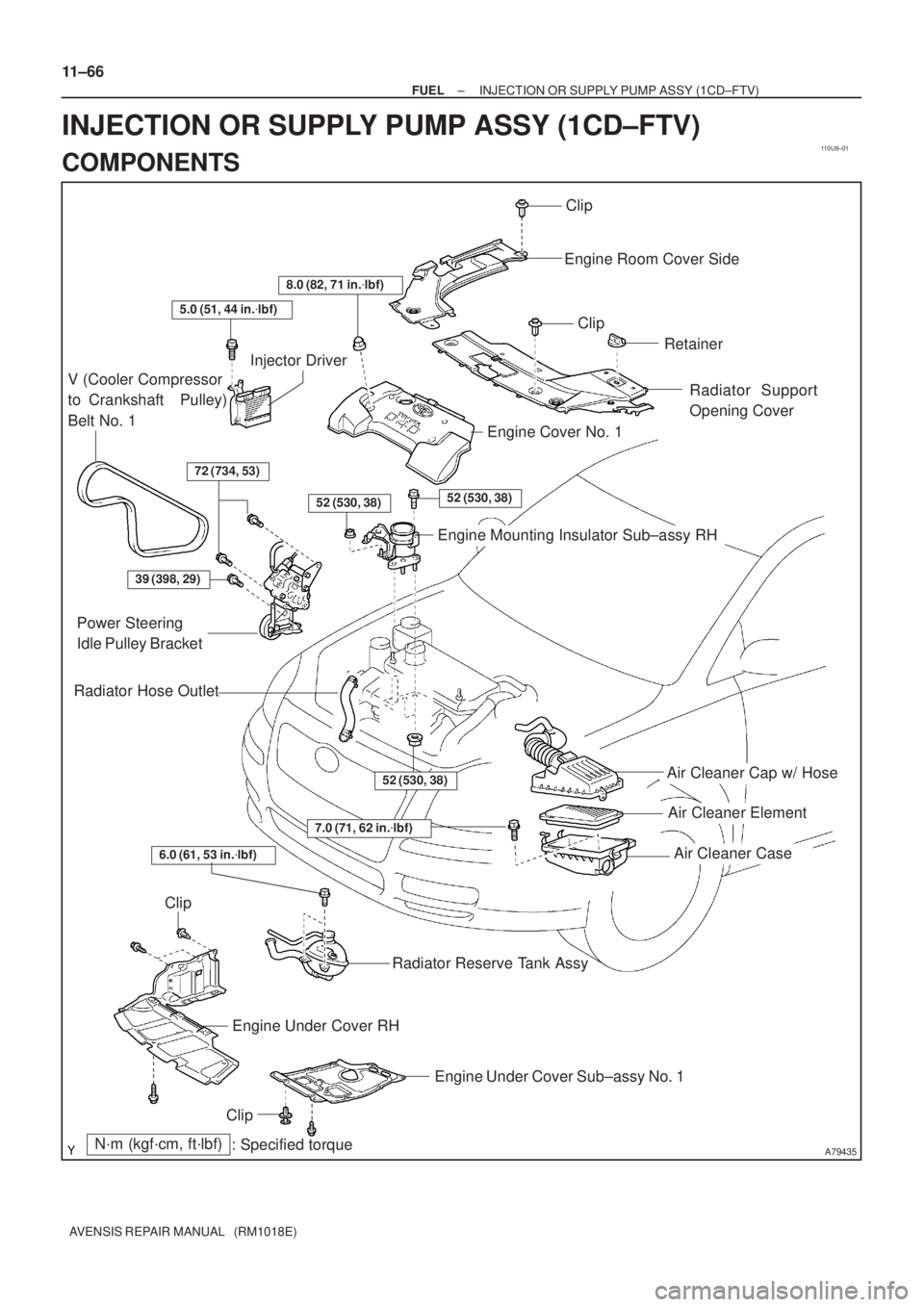
INJECTION OR SUPPLY PUMP ASSY (1CD±FTV)
COMPONENTS
Page 897 of 1690
550Z6±01
I35329
I35330
I35331
I35332
55±86
±
HEATER & AIR CONDITIONER W/PULLEY COMPRESSOR ASSY (1CD±FTV)
AVENSIS REPAIR MANUAL (RM1018E)
REPLACEMENT
1.DISCHARGE REFRIGERANT FROM REFRIGERATION SYSTEM (See page 55±38) SST 07110±58060 (07117±58080, 07117±58090, 07117±78050, 07117±88060, 07117±88070, 07117±88080)
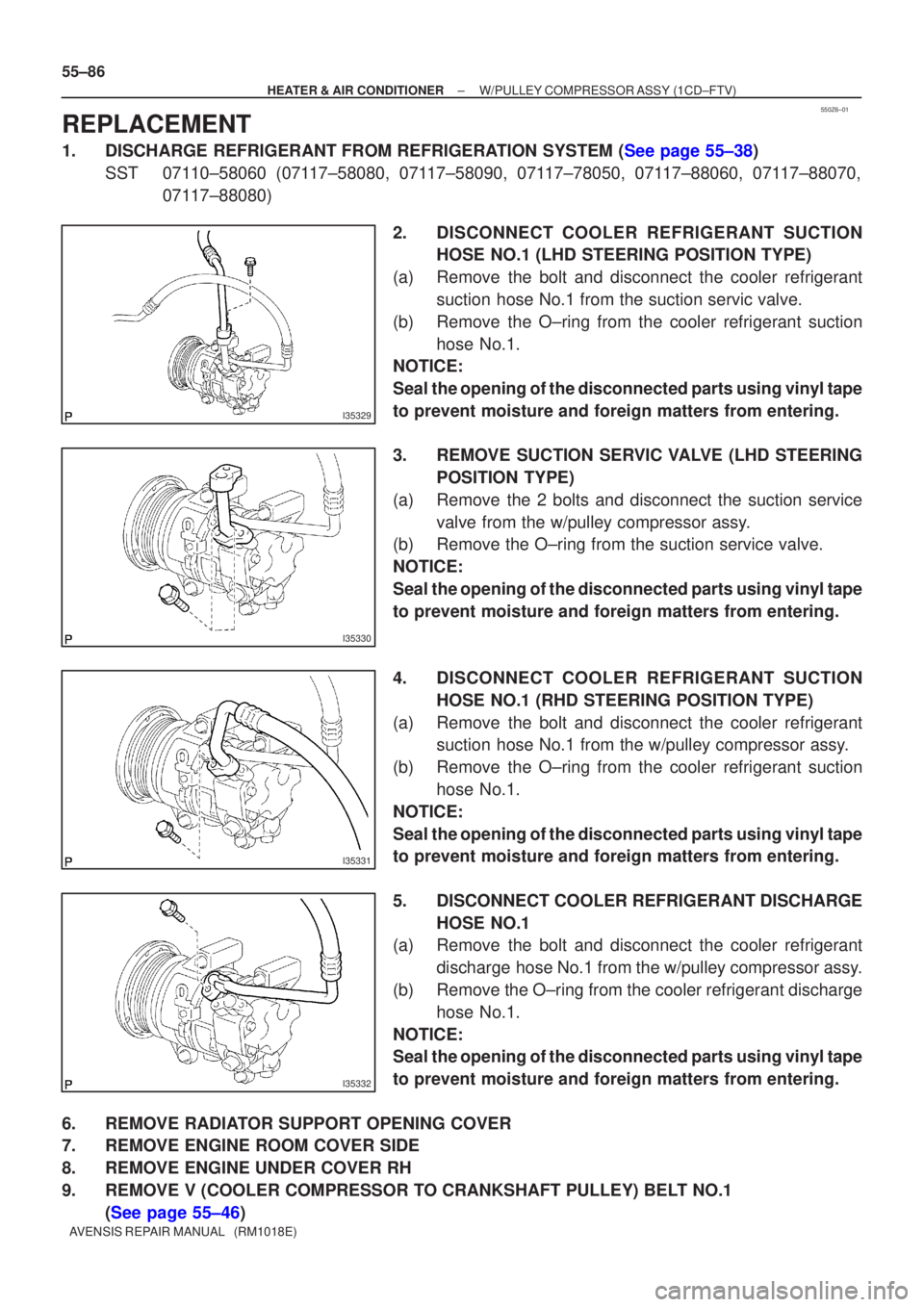
2. DISCONNECT COOLER REFRIGERANT SUCTIONHOSE NO.1 (LHD STEERING POSITION TYPE)
(a) Remove the bolt and disconnect the cooler refrigerant suction hose No.1 from the suction servic valve.
(b) Remove the O±ring from the cooler refrigerant suction hose No.1.
NOTICE:
Seal the opening of the disconnected parts using vinyl tape
to prevent moisture and foreign matters from entering.
3. REMOVE SUCTION SERVIC VALVE (LHD STEERING
POSITION TYPE)
(a) Remove the 2 bolts and disconnect the suction service valve from the w/pulley compressor assy.
(b) Remove the O±ring from the suction service valve.
NOTICE:
Seal the opening of the disconnected parts using vinyl tape
to prevent moisture and foreign matters from entering.
4. DISCONNECT COOLER REFRIGERANT SUCTION
HOSE NO.1 (RHD STEERING POSITION TYPE)
(a) Remove the bolt and disconnect the cooler refrigerant suction hose No.1 from the w/pulley compressor assy.
(b) Remove the O±ring from the cooler refrigerant suction hose No.1.
NOTICE:
Seal the opening of the disconnected parts using vinyl tape
to prevent moisture and foreign matters from entering.
5. DISCONNECT COOLER REFRIGERANT DISCHARGE HOSE NO.1
(a) Remove the bolt and disconnect the cooler refrigerant
discharge hose No.1 from the w/pulley compressor assy.
(b) Remove the O±ring from the cooler refrigerant discharge hose No.1.
NOTICE:
Seal the opening of the disconnected parts using vinyl tape
to prevent moisture and foreign matters from entering.
6. REMOVE RADIATOR SUPPORT OPENING COVER
7. REMOVE ENGINE ROOM COVER SIDE
8. REMOVE ENGINE UNDER COVER RH
9. REMOVE V (COOLER COMPRESSOR TO CRANKSHAFT PULLEY) BELT NO.1 (See page 55±46)
Page 899 of 1690
I35332
I35330
I35331
55±88
± HEATER & AIR CONDITIONERW/PULLEY COMPRESSOR ASSY (1CD±FTV)
AVENSIS REPAIR MANUAL (RM1018E)
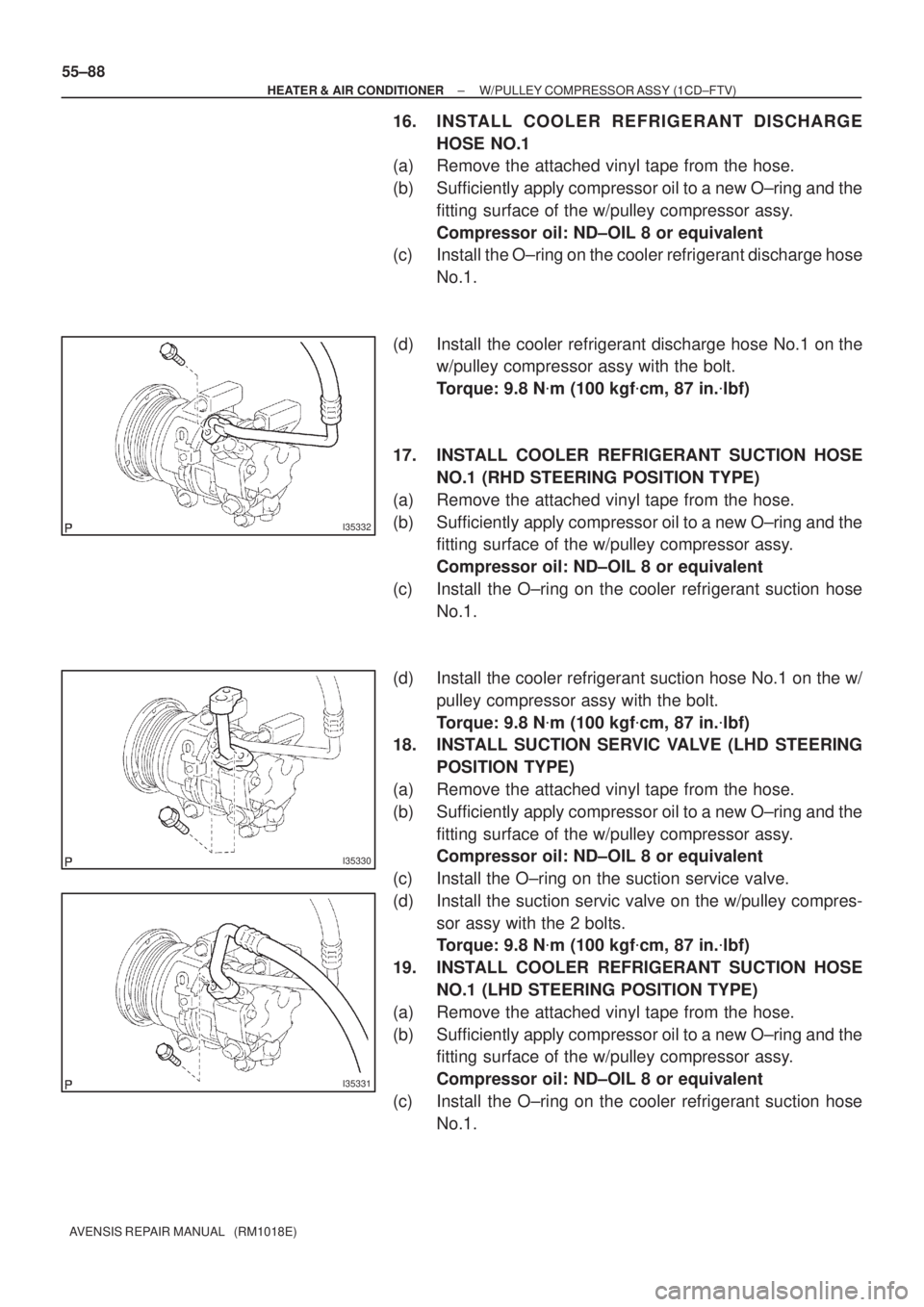
16. INSTALL COOLER REFRIGERANT DISCHARGE
HOSE NO.1
(a) Remove the attached vinyl tape from the hose.
(b) Sufficiently apply compressor oil to a new O±ring and the
fitting surface of the w/pulley compressor assy.
Compressor oil: ND±OIL 8 or equivalent
(c) Install the O±ring on the cooler refrigerant discharge hose
No.1.
(d) Install the cooler refrigerant discharge hose No.1 on the
w/pulley compressor assy with the bolt.
Torque: 9.8 N�m (100 kgf�cm, 87 in.�lbf)
17. INSTALL COOLER REFRIGERANT SUCTION HOSE
NO.1 (RHD STEERING POSITION TYPE)
(a) Remove the attached vinyl tape from the hose.
(b) Sufficiently apply compressor oil to a new O±ring and the
fitting surface of the w/pulley compressor assy.
Compressor oil: ND±OIL 8 or equivalent
(c) Install the O±ring on the cooler refrigerant suction hose
No.1.
(d) Install the cooler refrigerant suction hose No.1 on the w/
pulley compressor assy with the bolt.
Torque: 9.8 N�m (100 kgf�cm, 87 in.�lbf)
18. INSTALL SUCTION SERVIC VALVE (LHD STEERING
POSITION TYPE)
(a) Remove the attached vinyl tape from the hose.
(b) Sufficiently apply compressor oil to a new O±ring and the
fitting surface of the w/pulley compressor assy.
Compressor oil: ND±OIL 8 or equivalent
(c) Install the O±ring on the suction service valve.
(d) Install the suction servic valve on the w/pulley compres-
sor assy with the 2 bolts.
Torque: 9.8 N�m (100 kgf�cm, 87 in.�lbf)
19. INSTALL COOLER REFRIGERANT SUCTION HOSE
NO.1 (LHD STEERING POSITION TYPE)
(a) Remove the attached vinyl tape from the hose.
(b) Sufficiently apply compressor oil to a new O±ring and the
fitting surface of the w/pulley compressor assy.
Compressor oil: ND±OIL 8 or equivalent
(c) Install the O±ring on the cooler refrigerant suction hose
No.1.