Page 869 of 1767

Front Fog Lamp Aiming Adjustment
When performing fog lamp aiming adjustment, use an aiming
machine, aiming wall screen or headlamp tester. The aimer should
be in good operational condition, calibrated and used according to
the relevant operation manuals supplied with the unit.
If an aimer is not available, aiming adjustment can be done as fol-
lows:
For details, refer to the regulations in your own country.
CAUTION:
IKeep all tires inflated to correct pressures.
IPlace vehicle and tester on one and the same flat surface.
IEnsure that there is no-load in the vehicle other than
coolant, engine oil (filled up to correct level), full fuel tank
and the driver (or equivalent weight placed in driver's posi-
tion).
For details of front fog lamp aiming adjustment, refer to ªAiming
Adjustmentº, EL-43.
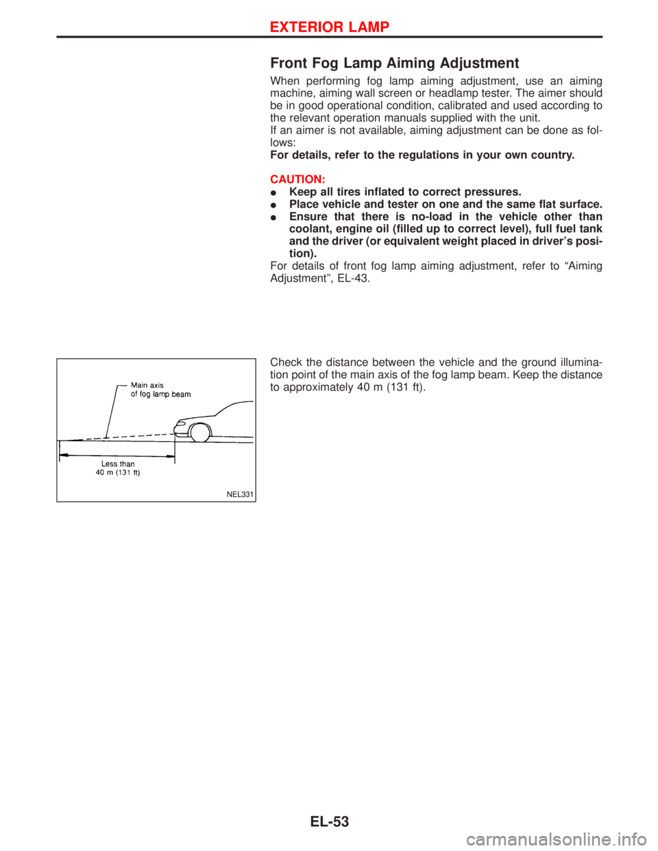
Check the distance between the vehicle and the ground illumina-
tion point of the main axis of the fog lamp beam. Keep the distance
to approximately 40 m (131 ft).
NEL331
EXTERIOR LAMP
EL-53
Page 1107 of 1767

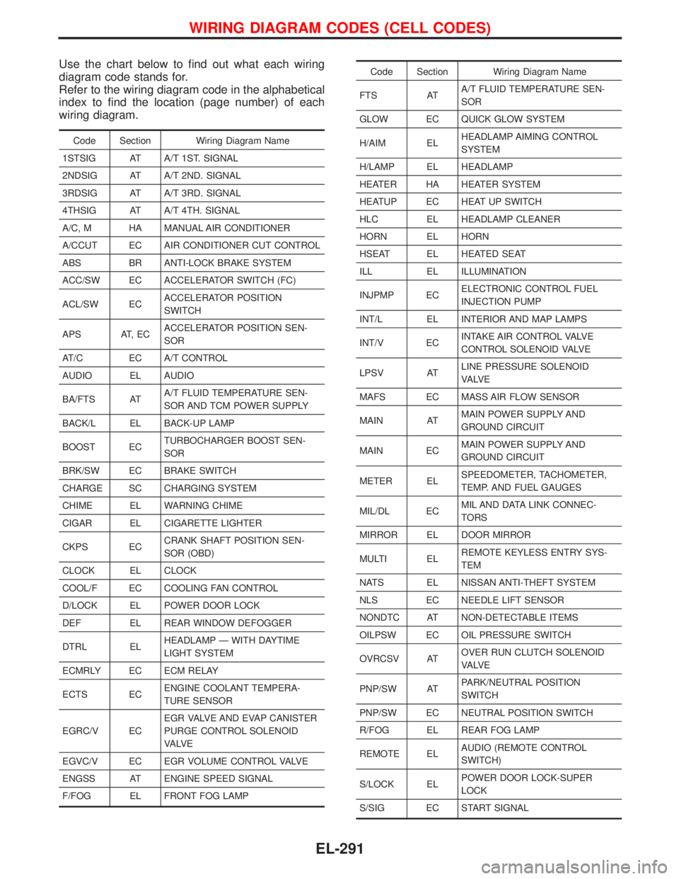
Use the chart below to find out what each wiring
diagram code stands for.
Refer to the wiring diagram code in the alphabetical
index to find the location (page number) of each
wiring diagram.
Code Section Wiring Diagram Name
1STSIG AT A/T 1ST. SIGNAL
2NDSIG AT A/T 2ND. SIGNAL
3RDSIG AT A/T 3RD. SIGNAL
4THSIG AT A/T 4TH. SIGNAL
A/C, M HA MANUAL AIR CONDITIONER
A/CCUT EC AIR CONDITIONER CUT CONTROL
ABS BR ANTI-LOCK BRAKE SYSTEM
ACC/SW EC ACCELERATOR SWITCH (FC)
ACL/SW ECACCELERATOR POSITION
SWITCH
APS AT, ECACCELERATOR POSITION SEN-
SOR
AT/C EC A/T CONTROL
AUDIO EL AUDIO
BA/FTS ATA/T FLUID TEMPERATURE SEN-
SOR AND TCM POWER SUPPLY
BACK/L EL BACK-UP LAMP
BOOST ECTURBOCHARGER BOOST SEN-
SOR
BRK/SW EC BRAKE SWITCH
CHARGE SC CHARGING SYSTEM
CHIME EL WARNING CHIME
CIGAR EL CIGARETTE LIGHTER
CKPS ECCRANK SHAFT POSITION SEN-
SOR (OBD)
CLOCK EL CLOCK
COOL/F EC COOLING FAN CONTROL
D/LOCK EL POWER DOOR LOCK
DEF EL REAR WINDOW DEFOGGER
DTRL ELHEADLAMP Ð WITH DAYTIME
LIGHT SYSTEM
ECMRLY EC ECM RELAY
ECTS ECENGINE COOLANT TEMPERA-
TURE SENSOR
EGRC/V ECEGR VALVE AND EVAP CANISTER
PURGE CONTROL SOLENOID
VA LV E
EGVC/V EC EGR VOLUME CONTROL VALVE
ENGSS AT ENGINE SPEED SIGNAL
F/FOG EL FRONT FOG LAMP
Code Section Wiring Diagram Name
FTS ATA/T FLUID TEMPERATURE SEN-
SOR
GLOW EC QUICK GLOW SYSTEM
H/AIM ELHEADLAMP AIMING CONTROL
SYSTEM
H/LAMP EL HEADLAMP
HEATER HA HEATER SYSTEM
HEATUP EC HEAT UP SWITCH
HLC EL HEADLAMP CLEANER
HORN EL HORN
HSEAT EL HEATED SEAT
ILL EL ILLUMINATION
INJPMP ECELECTRONIC CONTROL FUEL
INJECTION PUMP
INT/L EL INTERIOR AND MAP LAMPS
INT/V ECINTAKE AIR CONTROL VALVE
CONTROL SOLENOID VALVE
LPSV ATLINE PRESSURE SOLENOID
VA LV E
MAFS EC MASS AIR FLOW SENSOR
MAIN ATMAIN POWER SUPPLY AND
GROUND CIRCUIT
MAIN ECMAIN POWER SUPPLY AND
GROUND CIRCUIT
METER ELSPEEDOMETER, TACHOMETER,
TEMP. AND FUEL GAUGES
MIL/DL ECMIL AND DATA LINK CONNEC-
TORS
MIRROR EL DOOR MIRROR
MULTI ELREMOTE KEYLESS ENTRY SYS-
TEM
NATS EL NISSAN ANTI-THEFT SYSTEM
NLS EC NEEDLE LIFT SENSOR
NONDTC AT NON-DETECTABLE ITEMS
OILPSW EC OIL PRESSURE SWITCH
OVRCSV ATOVER RUN CLUTCH SOLENOID
VA LV E
PNP/SW ATPARK/NEUTRAL POSITION
SWITCH
PNP/SW EC NEUTRAL POSITION SWITCH
R/FOG EL REAR FOG LAMP
REMOTE ELAUDIO (REMOTE CONTROL
SWITCH)
S/LOCK ELPOWER DOOR LOCK-SUPER
LOCK
S/SIG EC START SIGNAL
WIRING DIAGRAM CODES (CELL CODES)
EL-291
Page 1111 of 1767
Parts Requiring Angular Tightening
IUse an angle wrench for the final tightening of the cylinder head
bolts.
IDo not use a torque value for final tightening.
IThe torque value for these parts are for a preliminary step.
IEnsure thread and seat surfaces are clean and coated with
engine oil.
Liquid Gasket Application Procedure
1.Use a scraper to remove old liquid gasket from mating
surfaces and grooves. Also, completely clean any oil from
these areas.
2.Apply a continuous bead of liquid gasket to mating sur-
faces. (Use Genuine Liquid Gasket or equivalent.)
IBe sure liquid gasket diameter is as specified.
3.Apply liquid gasket around the inner side of bolt holes
(unless otherwise specified).
4.Assembly should be done within 5 minutes after coating.
5.Wait at least 30 minutes before refilling engine oil and
engine coolant.
SEM164F
AEM080
PRECAUTIONSZD
EM-3
Page 1121 of 1767
REMOVAL
1. Remove the following parts.
IDrain engine coolant. Refer to MA section, ªChanging Engine
Coolantº.
IRemove engine cover. Refer to the figure at left.
IRemove intercooler.
IRemove air hose (on throttle body side).
IRemove injection tube.
IRemove or relocate wires/harnesses and tubes/pipes.
2. Remove intake manifold in the reverse order of that shown in
the figure.
Inspection
Clean surface of intake manifold.
Use a reliable straightedge and feeler gauge to check the flatness
of intake manifold surface.
Intake manifold surface flatness:
Limit 0.2 mm (0.008 in)
INSTALLATION
1. Tighten intake manifold in the numerical order shown in the
figure.
:25-28N×m (2.5 - 2.9 kg-m, 18 - 20 ft-lb)
2. Install in the reverse order of removal.
SEM293G
SEM294G
INTAKE MANIFOLDZD
Removal and Installation (Cont'd)
EM-13
Page 1122 of 1767
Removal and Installation
REMOVAL
1. Remove the following parts.
IUndercover
IUnder guard
IEngine coolant (drain)
Refer to MA section, ªChanging Engine Coolantº.
IExhaust front tube
Refer to FE section, ªRemoval and Installationº, ªEXHAUST
SYSTEMº.
IRemove wires, harnesses, tubes and pipes.
YEM038
SEM296G
CATALYST AND TURBOCHARGERZD
EM-14
Page 1134 of 1767
Removal and Installation
CAUTION:
As the internal mechanism of the idler gear must first of all,
and always, be set by a bolt when removing the timing chain
before removing the fuel injection pump and timing gear, fol-
low the procedures on EM-38, ªRemoval of timing chain after
setting idler gearº, ªElectronic controlled fuel injection pumpº.
IThis chapter will deal with the summary of removing the timing
chain before removing the camshaft and cylinder head.
Removal
1. Remove the following parts.
IEngine cover
IIntercooler
IAir inlet pipe
IThrottle body
IRocker cover
ISpill tube
ICoolant (Drain)
IRadiator upper hose
IWater outlet
IRadiator shroud
ICooling fan
IAuxiliary belt
IVacuum pipe
IVacuum pump
YEM028
TIMING CHAINZD
EM-26
Page 1171 of 1767
Precautions
IDo not perform operation unless it is perfectly safe.
IDo not start operation unless the exhaust system and coolant
are cooled down.
ILift the engine at the designated support points only.
IPerform operations for the items other than the engine body,
referring to the applicable sections.
IRefer to MT section and AT section for rear mount.
Removal
IAfter removing transmission, hoist the engine and remove it.
Preparation
1. Drain coolant from radiator drain plugs.
2. Remove the following parts.
IEngine hood
IUndercover
IUnder protector
IBattery
IIntercooler
IRadiator shroud
IRadiator
IAccessory belt
ICooling fan
IExhaust front tube
YEM032
ENGINE REMOVALZD
EM-63
Page 1172 of 1767

Engine room (Left)
3. Remove air duct and air cleaner case.
4. Disconnect vacuum hose to the vehicle on the engine.
5. Disconnect harness connectors from alternator and air com-
pressor.
6. Remove alternator.
7. After removing refrigerant, remove pipes of air compressor and
inlet/outlet.
8. Disconnect heating hose, install blank cap to hose to prevent
coolant from leaking.
9. Remove heating pipe.
10. Remove heat insulator.
11. Remove catalytic converter.
Engine room (Right)
12. Remove power steering reservoir tank from bracket, and fix it
to the vehicle with a rope.
CAUTION:
Keep the reservoir tank level when fixing to prevent oil leak.
13. Remove fuel feed and return hoses.
CAUTION:
Install blank caps immediately to avoid fuel leakage.
14. Remove all harness connectors on the engine, and move har-
nesses to the side of the vehicle.
Vehicle underfloor
15. Remove starter motor.
16. Detach A/T oil cooler pipes from oil pan. (A/T model)
17. Remove rear propeller shaft.
18. Remove mounting bolts to secure the engine to transmission.
1) Remove torque converter installation bolt. (A/T model)
2) Lift transmission bottom with transmission jack, and remove
rear mount members from the vehicle.
3) Lower transmission with the jack, and remove upper mounting
bolts securing the engine to transmission.
4) Lift transmission with the jack, and reinstall rear mount mem-
bers to the vehicle.
5) Position the jack to the front side of transmission.
6) Remove remaining mounting bolts securing the engine to trans-
mission.
Removal operation
19. Remove air conditioner high pressure pipes at the rear of the
engine room.
IThis is due to some inconvenience in the rear slinger installa-
tion.
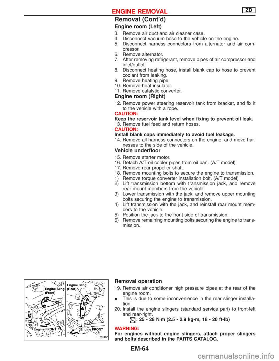
20. Install the engine slingers (standard service part) to front-left
and rear-right.
:25-28N×m (2.5 - 2.9 kg-m, 18 - 20 ft-lb)
WARNING:
For engines without engine slingers, attach proper slingers
and bolts described in the PARTS CATALOG.
FEM082
ENGINE REMOVALZD
Removal (Cont'd)
EM-64