2002 NISSAN TERRANO engine coolant
[x] Cancel search: engine coolantPage 669 of 1767
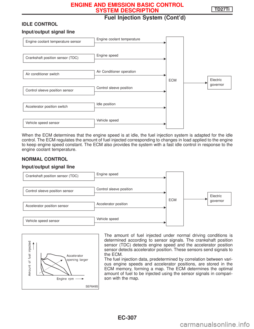
IDLE CONTROL
Input/output signal line
Engine coolant temperature sensorEEngine coolant temperature
ECM
EElectric
governor
Crankshaft position sensor (TDC)EEngine speed
Air conditioner switch
EAir Conditioner operation
Control sleeve position sensor
EControl sleeve position
Accelerator position switch
EIdle position
Vehicle speed sensor
EVehicle speed
When the ECM determines that the engine speed is at idle, the fuel injection system is adapted for the idle
control. The ECM regulates the amount of fuel injected corresponding to changes in load applied to the engine
to keep engine speed constant. The ECM also provides the system with a fast idle control in response to the
engine coolant temperature.
NORMAL CONTROL
Input/output signal line
Crankshaft position sensor (TDC)EEngine speed
ECM
EElectric
governor
Control sleeve position sensorEControl sleeve position
Accelerator position sensor
EAccelerator position
Vehicle speed sensor
EVehicle speed
The amount of fuel injected under normal driving conditions is
determined according to sensor signals. The crankshaft position
sensor (TDC) detects engine speed and the accelerator position
sensor detects accelerator position. These sensors send signals to
the ECM.
The fuel injection data, predetermined by correlation between vari-
ous engine speeds and accelerator positions, are stored in the
ECM memory, forming a map. The ECM determines the optimal
amount of fuel to be injected using the sensor signals in compari-
son with the map.
SEF649S
ENGINE AND EMISSION BASIC CONTROL
SYSTEM DESCRIPTIONTD27Ti
Fuel Injection System (Cont'd)
EC-307
Page 671 of 1767
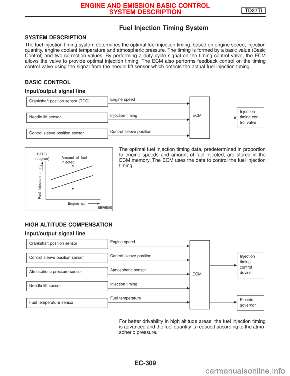
Fuel Injection Timing System
SYSTEM DESCRIPTION
The fuel injection timing system determines the optimal fuel injection timing, based on engine speed, injection
quantity, engine coolant temperature and atmospheric pressure. The timing is formed by a basic value (Basic
Control) and two correction values. By performing a duty cycle signal on the timing control valve, the ECM
allows the valve to provide optimal injection timing. The ECM also performs feedback control on the timing
control valve using the signal from the needle lift sensor which detects the actual fuel injection timing.
BASIC CONTROL
Input/output signal line
Crankshaft position sensor (TDC)EEngine speed
ECM
E
Injection
timing con-
trol valve
Needle lift sensorEInjection timing
Control sleeve position sensor
EControl sleeve position
The optimal fuel injection timing data, predetermined in proportion
to engine speeds and amount of fuel injected, are stored in the
ECM memory. The ECM uses the data to control the fuel injection
timing.
HIGH ALTITUDE COMPENSATION
Input/output signal line
Crankshaft position sensorEEngine speed
ECM
E
Injection
timing
control
deviceControl sleeve position sensorEControl sleeve position
Atmospheric pressure sensor
EAtmospheric sensor
Needle lift sensor
EInjection timing
Fuel temperature sensor
EFuel temperatureEElectric
governor
For better drivability in high altitude areas, the fuel injection timing
is advanced and the fuel quantity is reduced according to the atmo-
spheric pressure.
SEF650S
ENGINE AND EMISSION BASIC CONTROL
SYSTEM DESCRIPTIONTD27Ti
EC-309
Page 672 of 1767
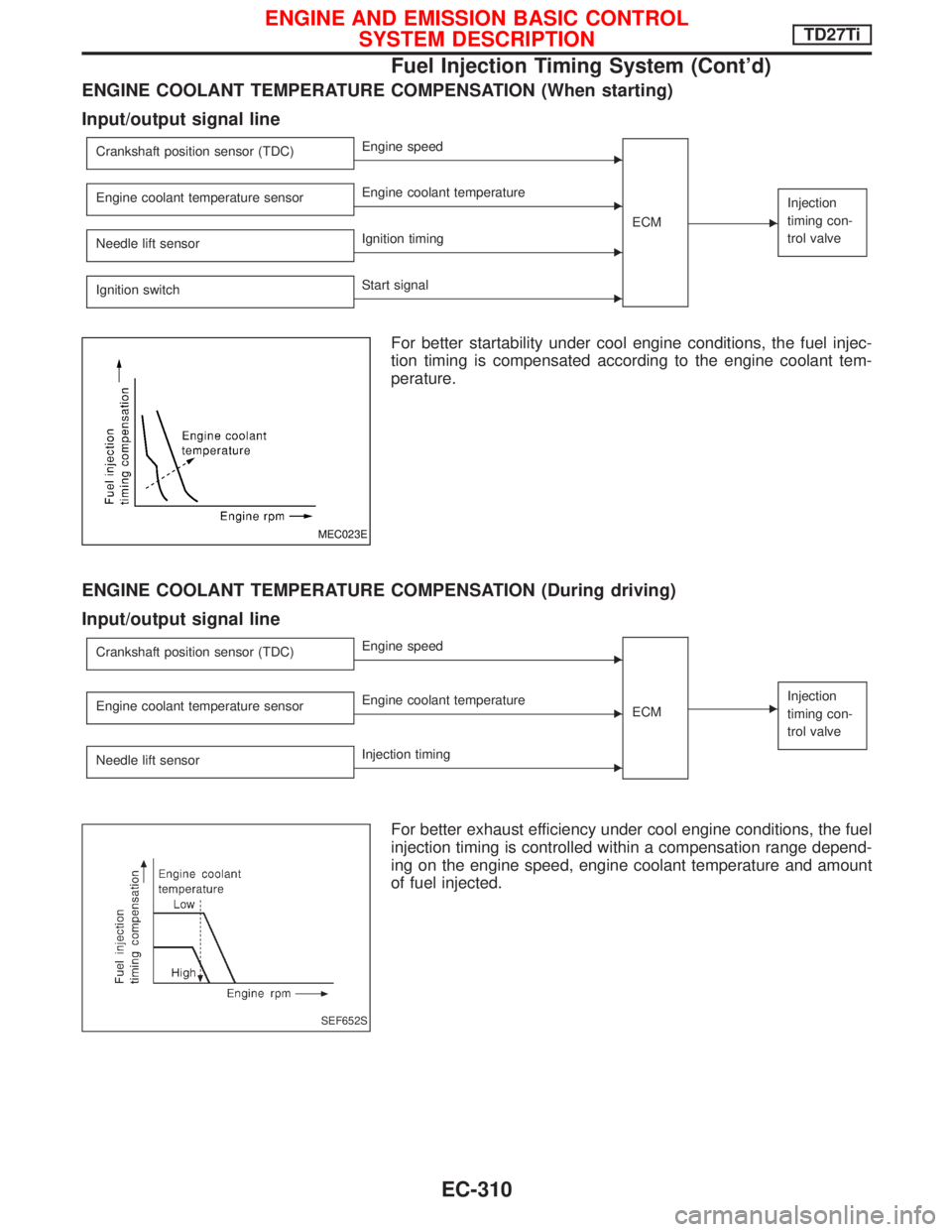
ENGINE COOLANT TEMPERATURE COMPENSATION (When starting)
Input/output signal line
Crankshaft position sensor (TDC)EEngine speed
ECM
E
Injection
timing con-
trol valveEngine coolant temperature sensorEEngine coolant temperature
Needle lift sensor
EIgnition timing
Ignition switch
EStart signal
For better startability under cool engine conditions, the fuel injec-
tion timing is compensated according to the engine coolant tem-
perature.
ENGINE COOLANT TEMPERATURE COMPENSATION (During driving)
Input/output signal line
Crankshaft position sensor (TDC)EEngine speed
ECM
EInjection
timing con-
trol valveEngine coolant temperature sensorEEngine coolant temperature
Needle lift sensor
EInjection timing
For better exhaust efficiency under cool engine conditions, the fuel
injection timing is controlled within a compensation range depend-
ing on the engine speed, engine coolant temperature and amount
of fuel injected.
MEC023E
SEF652S
ENGINE AND EMISSION BASIC CONTROL
SYSTEM DESCRIPTIONTD27Ti
Fuel Injection Timing System (Cont'd)
EC-310
Page 673 of 1767
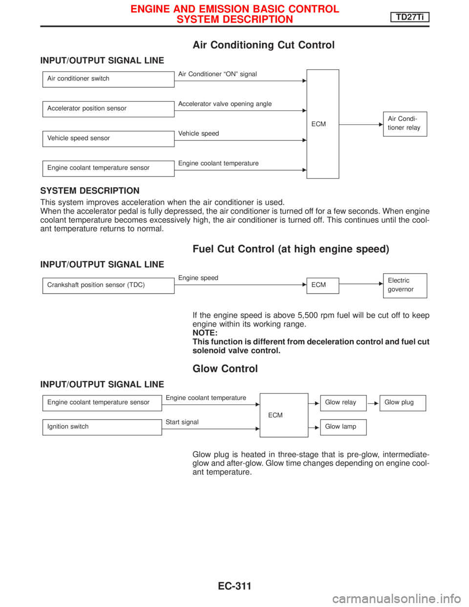
Air Conditioning Cut Control
INPUT/OUTPUT SIGNAL LINE
Air conditioner switchEAir Conditioner ªONº signal
ECM
EAir Condi-
tioner relay
Accelerator position sensorEAccelerator valve opening angle
Vehicle speed sensor
EVehicle speed
Engine coolant temperature sensor
EEngine coolant temperature
SYSTEM DESCRIPTION
This system improves acceleration when the air conditioner is used.
When the accelerator pedal is fully depressed, the air conditioner is turned off for a few seconds. When engine
coolant temperature becomes excessively high, the air conditioner is turned off. This continues until the cool-
ant temperature returns to normal.
Fuel Cut Control (at high engine speed)
INPUT/OUTPUT SIGNAL LINE
Crankshaft position sensor (TDC)EEngine speed
ECMEElectric
governor
If the engine speed is above 5,500 rpm fuel will be cut off to keep
engine within its working range.
NOTE:
This function is different from deceleration control and fuel cut
solenoid valve control.
Glow Control
INPUT/OUTPUT SIGNAL LINE
Engine coolant temperature sensorEEngine coolant temperature
ECMEGlow relayEGlow plug
Ignition switchEStart signalEGlow lamp
Glow plug is heated in three-stage that is pre-glow, intermediate-
glow and after-glow. Glow time changes depending on engine cool-
ant temperature.
ENGINE AND EMISSION BASIC CONTROL
SYSTEM DESCRIPTIONTD27Ti
EC-311
Page 690 of 1767
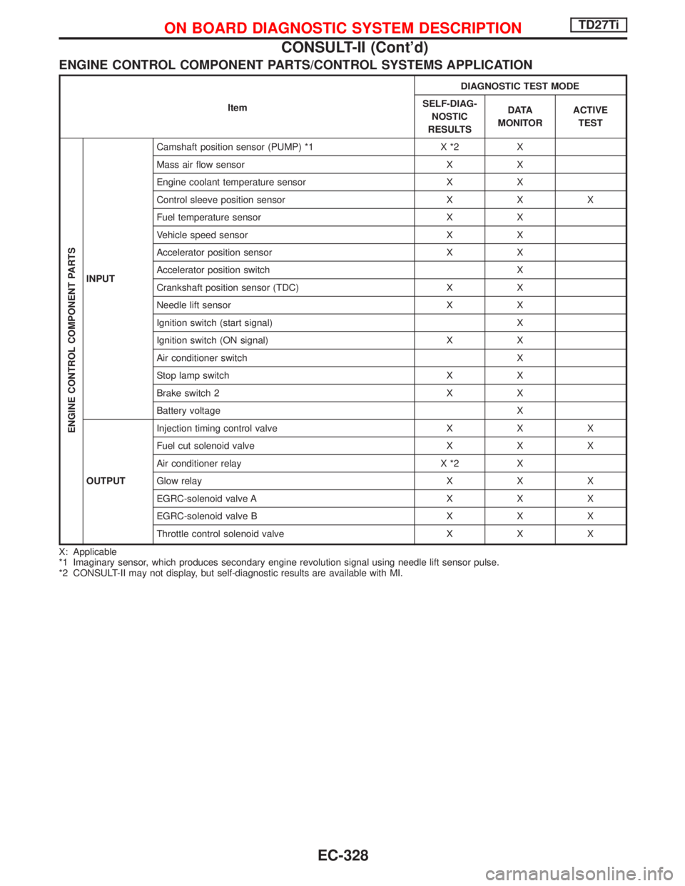
ENGINE CONTROL COMPONENT PARTS/CONTROL SYSTEMS APPLICATION
ItemDIAGNOSTIC TEST MODE
SELF-DIAG-
NOSTIC
RESULTSD ATA
MONITORACTIVE
TEST
ENGINE CONTROL COMPONENT PARTS
INPUTCamshaft position sensor (PUMP) *1 X *2 X
Mass air flow sensor X X
Engine coolant temperature sensor X X
Control sleeve position sensor X X X
Fuel temperature sensor X X
Vehicle speed sensor X X
Accelerator position sensor X X
Accelerator position switch X
Crankshaft position sensor (TDC) X X
Needle lift sensor X X
Ignition switch (start signal) X
Ignition switch (ON signal) X X
Air conditioner switch X
Stop lamp switch X X
Brake switch 2 X X
Battery voltage X
OUTPUTInjection timing control valve X X X
Fuel cut solenoid valve X X X
Air conditioner relay X *2 X
Glow relay X X X
EGRC-solenoid valve A X X X
EGRC-solenoid valve B X X X
Throttle control solenoid valve X X X
X: Applicable
*1 Imaginary sensor, which produces secondary engine revolution signal using needle lift sensor pulse.
*2 CONSULT-II may not display, but self-diagnostic results are available with MI.
ON BOARD DIAGNOSTIC SYSTEM DESCRIPTIONTD27Ti
CONSULT-II (Cont'd)
EC-328
Page 691 of 1767
![NISSAN TERRANO 2002 Service Repair Manual SELF-DIAGNOSTIC MODE
Regarding items detected in ªSELF-DIAG RESULTSº mode, refer to ªTROUBLE DIAGNOSIS Ð INDEXº,
EC-293.
DATA MONITOR MODE
Monitored item
[Unit]ECM
input
signalsMain
signalsDescri NISSAN TERRANO 2002 Service Repair Manual SELF-DIAGNOSTIC MODE
Regarding items detected in ªSELF-DIAG RESULTSº mode, refer to ªTROUBLE DIAGNOSIS Ð INDEXº,
EC-293.
DATA MONITOR MODE
Monitored item
[Unit]ECM
input
signalsMain
signalsDescri](/manual-img/5/57393/w960_57393-690.png)
SELF-DIAGNOSTIC MODE
Regarding items detected in ªSELF-DIAG RESULTSº mode, refer to ªTROUBLE DIAGNOSIS Ð INDEXº,
EC-293.
DATA MONITOR MODE
Monitored item
[Unit]ECM
input
signalsMain
signalsDescription Remarks
CKPS×RPM
(TDC) [rpm]
qq
IThe engine speed computed from the
crankshaft position sensor (TDC) signal
is displayed.
CMPS×RPM -
PUMP [rpm]
qqIThe engine speed computed from the
needle lift sensor signal is displayed.
COOLAN TEMP/S
[ÉC] or [ÉF]
qq
IThe engine coolant temperature (deter-
mined by the signal voltage of the engine
coolant temperature sensor) is displayed.IWhen the engine coolant temperature
sensor is open or short-circuited, ECM
enters fail-safe mode. The same data as
the fuel temperature is displayed.
VHCL SPEED SE
[km/h] or [mph]
qqIThe vehicle speed computed from the
vehicle speed sensor signal is displayed.
FUEL TEMP SEN
[ÉC] or [ÉF]
qq
IThe fuel temperature (determined by the
signal voltage of the fuel temperature
sensor) is displayed.
ACCEL POS SEN [V]
qqIThe accelerator position sensor signal
voltage is displayed.
OFF ACCEL POS
[ON/OFF]
qqIIndicates [ON/OFF] condition from the
accelerator position switch signal.ISignal at approximately 9É opened.
C/SLEEV POS/S [V]
qqIThe control sleeve position sensor signal
voltage is displayed.
BATTERY VOLT [V]
qqIThe power supply voltage of ECM is dis-
played.
START SIGNAL
[ON/OFF]
qqIIndicates [ON/OFF] condition from the
starter signal.IAfter starting the engine, [OFF] is dis-
played regardless of the starter signal.
AIR COND SIG
[ON/OFF]
qq
IIndicates [ON/OFF] condition of the air
conditioner switch as determined by the
air conditioner signal.
BRAKE SW
[ON/OFF]
qIIndicates [ON/OFF] condition of the stop
lamp switch.
BRAKE SW2
[ON/OFF]
qIIndicates [ON/OFF] condition of the
brake switch 2.
IGN SW
[ON/OFF]
qqIIndicates [ON/OFF] condition from igni-
tion switch.
MAS AIR/FL SE [V]
qqIThe signal voltage of the mass air flow
sensor is displayed.IWhen the engine is stopped, a certain
value is indicated.
ACT INJ TIMG [É]
q
IThe actual injection timing angle deter-
mined by the ECM (an approximate aver-
age angle between injection start and
end from TDC) is displayed.
TARGET F/INJ
[mm
3/stroke]qIThe target fuel injection quantity (deter-
mined by the ECM according to the input
signal) is indicated.
NOTE:
Any monitored item that does not match the vehicle being diagnosed is deleted from the display automatically.
ON BOARD DIAGNOSTIC SYSTEM DESCRIPTIONTD27Ti
CONSULT-II (Cont'd)
EC-329
Page 702 of 1767
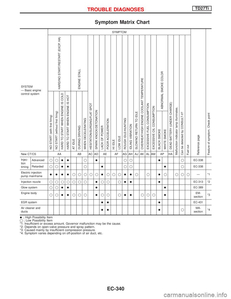
Symptom Matrix Chart
SYSTEM
Ð Basic engine
control systemSYMPTOM
Reference page
Feature of symptom, Check pointHARD/NO START/RESTART (EXCP. HA)
ENGINE STALL
HESITATION/SURGING/FLAT SPOT
SPARK KNOCK/DETONATION
LACK OF POWER
POOR ACCELERATION
HI IDLE
LOW IDLE
ROUGH IDLE/HUNTING
IDLING VIBRATION
SLOW/NO RETURN TO IDLE
OVERHEAT/HIGH ENGINE COOLANT TEMPERATURE
EXCESSIVE FUEL CONSUMPTION
EXCESSIVE OIL CONSUMPTION
ABNORMAL SMOKE COLOR
DEAD BATTERY (UNDER CHARGE)
Malfunction indicator lamp illuminates.
Can be detected by CONSULT-II?
Fuel cutNO START (with first firing)
NO START (without first firing)
HARD TO START WHEN ENGINE IS COLD
HARD TO START WHEN ENGINE IS HOT
AT IDLE
DURING DRIVING
WHEN DECELERATING
BLACK SMOKE
WHITE SMOKENew CT/CS AA AB AC AD AE AF AG AH AJ AK AL AM AP HA
Injec-
tion
timingAdvancedqq
IIqIqqIqEC-338
Retardedqq
IIqIqqIqEC-338
Electric injection
pump mainframe
IIIIqqqqqIqqqIIqqIq qqqÐ*1
Injection nozzleqqqqqqq
Iqq qII IEC-313 *2
Glow systemqq
II I IEC-389
Engine body
qq
IIqqqIqq qIIqqqIEM-
section*3
EGR system
II IEC-431
Air cleaner and
ducts
II IqMA-
section*4
I; High Possibility Item
q; Low Possibility Item
*1: Insufficient or excess amount. Governor malfunction may be the cause.
*2: Depends on open-valve pressure and spray pattern.
*3: Caused mainly by insufficient compression pressure.
*4: Symptom varies depending on off-position of air duct, etc.
TROUBLE DIAGNOSESTD27Ti
EC-340
Page 703 of 1767
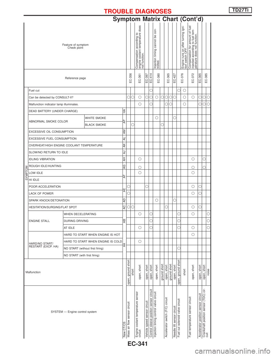
SYSTEM Ð Engine control system Malfunction
SYMPTOM
Reference page Feature of symptom
Check point
HARD/NO START/
RESTART (EXCP. HA) ENGINE STALL HESITATION/SURGING/FLAT SPOT SPARK KNOCK/DETONATION
LACK OF POWER
POOR ACCELERATION
HI IDLE
LOW IDLE
ROUGH IDLE/HUNTING
IDLING VIBRATION
SLOW/NO RETURN TO IDLE
OVERHEAT/HIGH ENGINE COOLANT TEMPERATURE
EXCESSIVE FUEL CONSUMPTION
EXCESSIVE OIL CONSUMPTION ABNORMAL SMOKE COLOR
DEAD BATTERY (UNDER CHARGE) Malfunction indicator lamp illuminates.
Can be detected by CONSULT-II?
Fuel cut
NO START (with first firing) NO START (without first firing)
HARD TO START WHEN ENGINE IS COLD
HARD TO START WHEN ENGINE IS HOT
AT IDLE
DURING DRIVING
WHEN DECELERATINGBLACK SMOKE WHITE SMOKE
New CT/CS AA AB AC AD AE AF AG AH AJ AK AL AM AP HA
Mass air flow sensor circuit open, ground shortqqq q
EC-356
shortqqq
Engine coolant temperature sensor
circuit open, shortqqq qqq qqEC-361Compensation according to
engine coolant temperature does
not function.
Vehicle speed sensor circuit open, shortqqEC-397
Control sleeve position sensor circuit open, shortqqqqqqEC-414
Injection timing control valve circuit
open, shortqqq
EC-380Injection timing cannot be con-
trolled.
ground shortqq
Accelerator switch (F/C) circuit open, shortqqq
EC-365
ground shortqq
Needle lift sensor circuit open, shortqqqEC-427
Fuel cut solenoid valve circuit open, ground shortq qqqq
EC-376
shortqqqEngine runs on after turning igni-
tion switch OFF.
Fuel temperature sensor circuit
open, shortqq qq qq qq q qEC-372Compensation for amount of fuel
injected according to fuel tem-
perature does not function.
Accelerator position sensor circuit open, shortqqq qqEC-365
Crankshaft position sensor (TDC) cir-
cuitopen, shortqq qq
EC-385
noiseqqqqq
TROUBLE DIAGNOSESTD27Ti
Symptom Matrix Chart (Cont'd)
EC-341