Page 704 of 1767

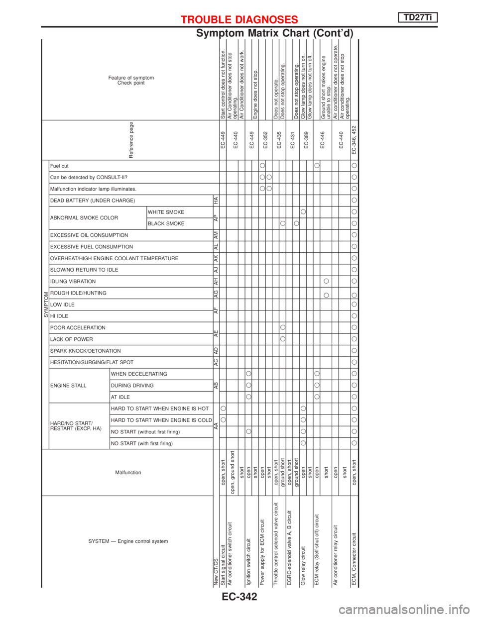
SYSTEM Ð Engine control systemMalfunction
SYMPTOM
Reference page
Feature of symptom
Check point
HARD/NO START/
RESTART (EXCP. HA) ENGINE STALL HESITATION/SURGING/FLAT SPOT SPARK KNOCK/DETONATION
LACK OF POWER
POOR ACCELERATION
HI IDLE
LOW IDLE
ROUGH IDLE/HUNTING
IDLING VIBRATION
SLOW/NO RETURN TO IDLE
OVERHEAT/HIGH ENGINE COOLANT TEMPERATURE
EXCESSIVE FUEL CONSUMPTION
EXCESSIVE OIL CONSUMPTION ABNORMAL SMOKE COLOR
DEAD BATTERY (UNDER CHARGE) Malfunction indicator lamp illuminates.
Can be detected by CONSULT-II?
Fuel cut
NO START (with first firing) NO START (without first firing)
HARD TO START WHEN ENGINE IS COLD
HARD TO START WHEN ENGINE IS HOT
AT IDLE
DURING DRIVING
WHEN DECELERATINGBLACK SMOKE WHITE SMOKE
New CT/CS AA AB AC AD AE AF AG AH AJ AK AL AM AP HA
Start signal circuit open, shortqqEC-449 Start control does not function.
Air conditioner switch circuit
open, ground short
EC-440Air Conditioner does not stop
operating.
shortAir Conditioner does not work.
Ignition switch circuit openq qqq
EC-449
shortEngine does not stop.
Power supply for ECM circuit openqqq
EC-352
shortqq
Throttle control solenoid valve circuit open, short
EC-435Does not operate.
ground shortqq qDoes not stop operating.
EGRC-solenoid valve A, B circuit open, short
EC-431
ground shortqDoes not stop operating.
Glow relay circuit openqqqqq
EC-389Glow lamp does not turn on.
shortGlow lamp does not turn off.
ECM relay (Self-shut off) circuit openqqqq
EC-446
shortqqGround short makes engine
unable to stop.
Air conditioner relay circuit open
EC-440Air conditioner does not operate.
shortAir conditioner does not stop
operating.
ECM, Connector circuit open, shortqqqqqqqqqqqqqq qqqqqqqqqqqEC-346, 452
TROUBLE DIAGNOSESTD27Ti
Symptom Matrix Chart (Cont'd)
EC-342
Page 711 of 1767
![NISSAN TERRANO 2002 Service Repair Manual TERMI-
NAL
NO.WIRE
COLORITEM CONDITIONDATA (DC Voltage and
Pulse Signal)
322 BControl sleeve position
sensor ground[Engine is running]
IIdle speedApproximately 2.6V
NEF476
325 L ECM relay (Self-shutof NISSAN TERRANO 2002 Service Repair Manual TERMI-
NAL
NO.WIRE
COLORITEM CONDITIONDATA (DC Voltage and
Pulse Signal)
322 BControl sleeve position
sensor ground[Engine is running]
IIdle speedApproximately 2.6V
NEF476
325 L ECM relay (Self-shutof](/manual-img/5/57393/w960_57393-710.png)
TERMI-
NAL
NO.WIRE
COLORITEM CONDITIONDATA (DC Voltage and
Pulse Signal)
322 BControl sleeve position
sensor ground[Engine is running]
IIdle speedApproximately 2.6V
NEF476
325 L ECM relay (Self-shutoff)[Ignition switch ªONº]
[Ignition switch ªOFFº]
IFor a few seconds after turning ignition switch
ªOFFºApproximately 1.4V
[Ignition switch ªOFFº]
IA few seconds passed after turning ignition switch
ªOFFºBATTERY VOLTAGE
(11 - 14V)
331 L/RCrankshaft position sensor
(TDC) ground[Engine is running]
IWarm-up condition
IIdle speedApproximately 0V
333 R Needle lift sensor ground[Ignition switch ªONº]Approximately 0V
334 G/REngine coolant tempera-
ture sensor ground[Ignition switch ªONº]Approximately 0V
335 G/RFuel temperature sensor
ground[Engine is running]Approximately 0V
344 L/GCrankshaft position sensor
(TDC)[Engine is running]
IWarm-up condition
IIdle speedApproximately 0V
SEF333Y
[Engine is running]
IWarm-up condition
IEngine speed is 2,000 rpmApproximately 0V
SEF334Y
345 G Needle lift sensor[Engine is running]
IWarm-up condition
IIdle speedApproximately 3.5V
[Engine is running]
IWarm-up condition
IEngine speed is 2,000 rpmApproximately 3.5V
TROUBLE DIAGNOSESTD27Ti
ECM Terminals and Reference Value (Cont'd)
EC-349
Page 712 of 1767
![NISSAN TERRANO 2002 Service Repair Manual TERMI-
NAL
NO.WIRE
COLORITEM CONDITIONDATA (DC Voltage and
Pulse Signal)
347 LG/WEngine coolant tempera-
ture sensor[Engine is running]Approximately 0 - 4.8V
Output voltage varies with
engine coolant NISSAN TERRANO 2002 Service Repair Manual TERMI-
NAL
NO.WIRE
COLORITEM CONDITIONDATA (DC Voltage and
Pulse Signal)
347 LG/WEngine coolant tempera-
ture sensor[Engine is running]Approximately 0 - 4.8V
Output voltage varies with
engine coolant](/manual-img/5/57393/w960_57393-711.png)
TERMI-
NAL
NO.WIRE
COLORITEM CONDITIONDATA (DC Voltage and
Pulse Signal)
347 LG/WEngine coolant tempera-
ture sensor[Engine is running]Approximately 0 - 4.8V
Output voltage varies with
engine coolant tempera-
ture
348 Y/B Fuel temperature sensor[Engine is running]0.6-5V
Output voltage varies with
fuel temperature.
349 G/RInjection timing control
valve ground[Ignition switch ªONº]Approximately 0V
403 G/R Air conditioner switch[Engine is running]
IAir conditioner switch is ªOFFºBATTERY VOLTAGE
(11 - 14V)
[Engine is running]
IBoth air conditioner switch and blower fan switch
are ªONº
(Compressor is operating)Approximately 0.1V
405 G/Y Stop lamp switch[Ignition switch ªONº]
IBrake pedal fully releasedApproximately 0V
[Ignition switch ªONº]
IBrake pedal depressedBATTERY VOLTAGE
(11 - 14V)
416 Y/RBrake pedal position
switch[Ignition switch ªONº]
IBrake pedal fully releasedBATTERY VOLTAGE
(11 - 14V)
[Ignition switch ªONº]
IBrake pedal depressedApproximately 0V
415 OR
Data link connector for
CONSULT-II[Engine is running]
IIdle speed (CONSULT-II is connected and turned
on)Approximately 0V
420 OR/RBATTERY VOLTAGE
(11 - 14V)
417 Y/B Vehicle speed sensor[Engine is running]
ILift up the vehicle
IIn 1st gear position
IVehicle speed is 10 km/h (6 MPH)0 - Approximately 8V
SEF891Y
[Engine is running]
ILift up the vehicle
IIn 2nd gear position
IVehicle speed is 30 km/h (19 MPH)Approximately 6V
SEF892Y
422 PU Start signal[Ignition switch ªONº]Approximately 0V
[Ignition switch ªSTARTº]BATTERY VOLTAGE
(11 - 14V)
425 R/BAccelerator position sen-
sor ground[Engine is running]
IWarm-up condition
IIdle speedApproximately 0V
TROUBLE DIAGNOSESTD27Ti
ECM Terminals and Reference Value (Cont'd)
EC-350
Page 723 of 1767

Component Description
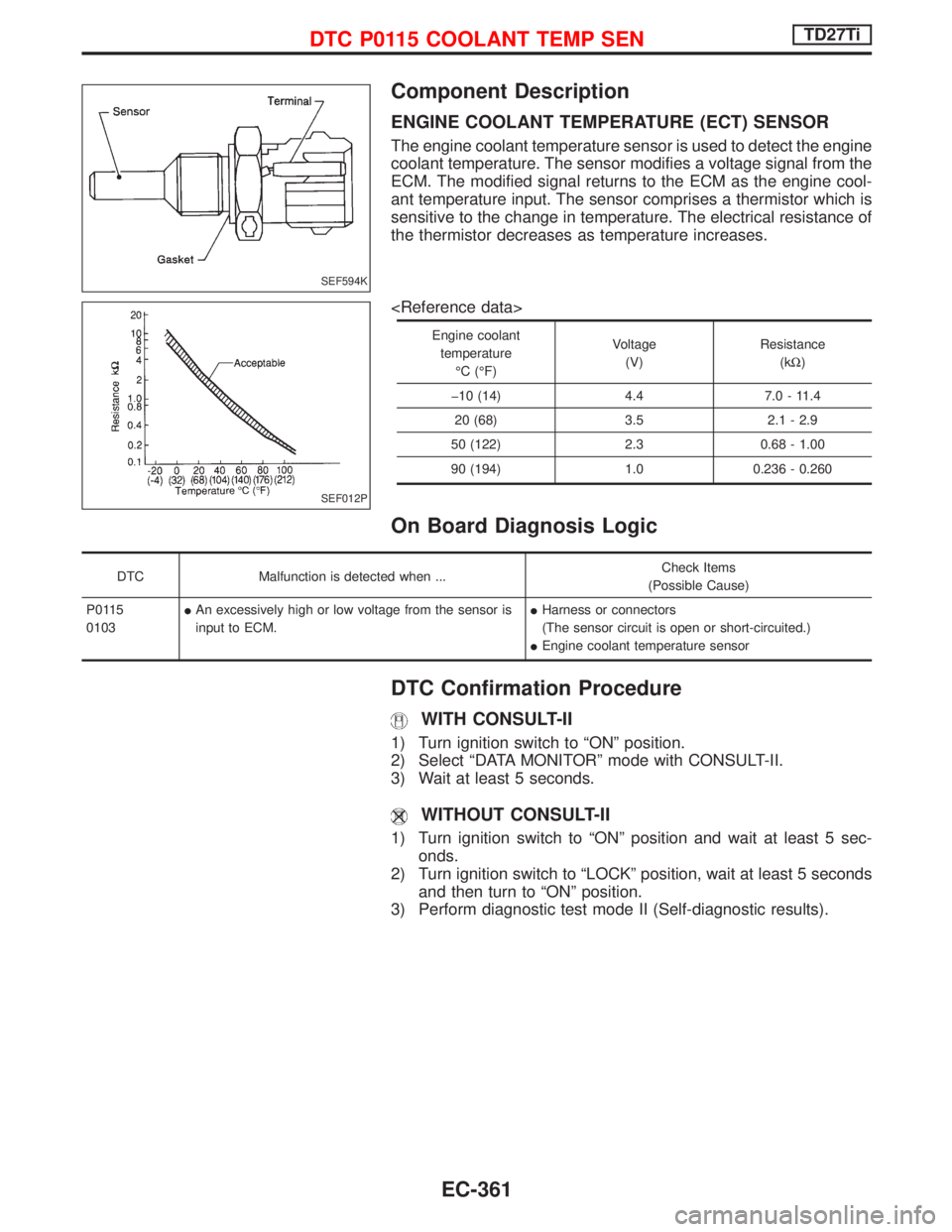
ENGINE COOLANT TEMPERATURE (ECT) SENSOR
The engine coolant temperature sensor is used to detect the engine
coolant temperature. The sensor modifies a voltage signal from the
ECM. The modified signal returns to the ECM as the engine cool-
ant temperature input. The sensor comprises a thermistor which is
sensitive to the change in temperature. The electrical resistance of
the thermistor decreases as temperature increases.
Engine coolant
temperature
ÉC (ÉF)Voltage
(V)Resistance
(kW)
þ10 (14) 4.4 7.0 - 11.4
20 (68) 3.5 2.1 - 2.9
50 (122) 2.3 0.68 - 1.00
90 (194) 1.0 0.236 - 0.260
On Board Diagnosis Logic
DTC Malfunction is detected when ...Check Items
(Possible Cause)
P0115
0103IAn excessively high or low voltage from the sensor is
input to ECM.IHarness or connectors
(The sensor circuit is open or short-circuited.)
IEngine coolant temperature sensor
DTC Confirmation Procedure
WITH CONSULT-II
1) Turn ignition switch to ªONº position.
2) Select ªDATA MONITORº mode with CONSULT-II.
3) Wait at least 5 seconds.
WITHOUT CONSULT-II
1) Turn ignition switch to ªONº position and wait at least 5 sec-
onds.
2) Turn ignition switch to ªLOCKº position, wait at least 5 seconds
and then turn to ªONº position.
3) Perform diagnostic test mode II (Self-diagnostic results).
SEF594K
SEF012P
DTC P0115 COOLANT TEMP SENTD27Ti
EC-361
Page 725 of 1767

Diagnostic Procedure
INSPECTION START
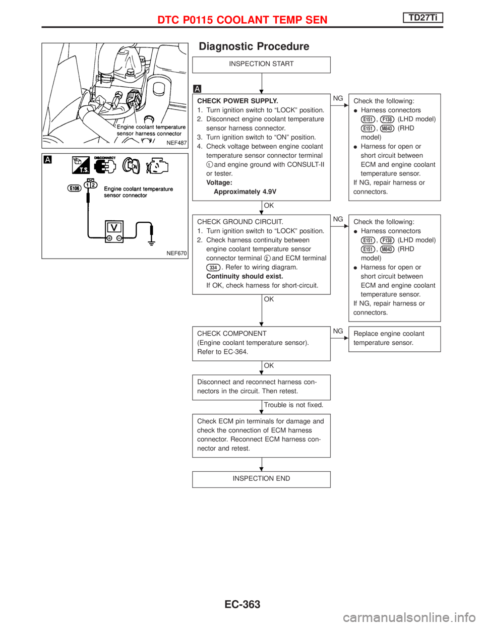
CHECK POWER SUPPLY.
1. Turn ignition switch to ªLOCKº position.
2. Disconnect engine coolant temperature
sensor harness connector.
3. Turn ignition switch to ªONº position.
4. Check voltage between engine coolant
temperature sensor connector terminal
q
1and engine ground with CONSULT-II
or tester.
Voltage:
Approximately 4.9V
OK
ENG
Check the following:
IHarness connectors
E151,F138(LHD model)
E151,M843(RHD
model)
IHarness for open or
short circuit between
ECM and engine coolant
temperature sensor.
If NG, repair harness or
connectors.
CHECK GROUND CIRCUIT.
1. Turn ignition switch to ªLOCKº position.
2. Check harness continuity between
engine coolant temperature sensor
connector terminalq
2and ECM terminal
334. Refer to wiring diagram.
Continuity should exist.
If OK, check harness for short-circuit.
OK
ENG
Check the following:
IHarness connectors
E151,F138(LHD model)
E151,M843(RHD
model)
IHarness for open or
short circuit between
ECM and engine coolant
temperature sensor.
If NG, repair harness or
connectors.
CHECK COMPONENT
(Engine coolant temperature sensor).
Refer to EC-364.
OK
ENG
Replace engine coolant
temperature sensor.
Disconnect and reconnect harness con-
nectors in the circuit. Then retest.
Trouble is not fixed.
Check ECM pin terminals for damage and
check the connection of ECM harness
connector. Reconnect ECM harness con-
nector and retest.
INSPECTION END
NEF487
NEF670
H
H
H
H
H
H
DTC P0115 COOLANT TEMP SENTD27Ti
EC-363
Page 726 of 1767
Component Inspection
ENGINE COOLANT TEMPERATURE SENSOR
Check resistance as shown in the figure.
Temperature ÉC (ÉF) Resistance kW
20 (68) 2.1 - 2.9
50 (122) 0.68 - 1.0
90 (194) 0.236 - 0.260
If NG, replace engine coolant temperature sensor.SEF152P
SEF012P
DTC P0115 COOLANT TEMP SENTD27Ti
EC-364
Page 751 of 1767

System Description
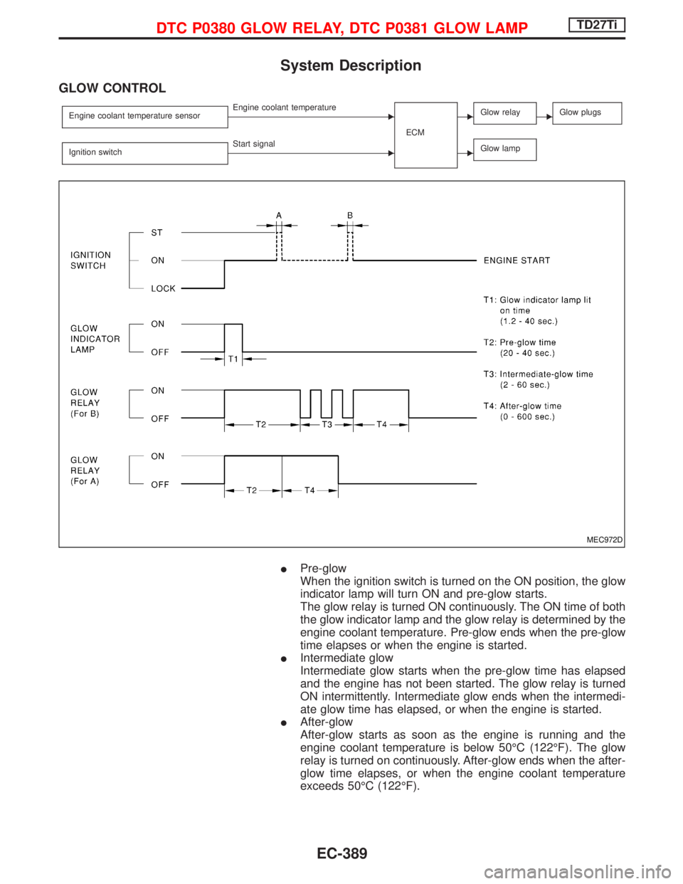
GLOW CONTROL
Engine coolant temperature sensorEEngine coolant temperature
ECMEGlow relayEGlow plugs
Ignition switchEStart signalEGlow lamp
IPre-glow
When the ignition switch is turned on the ON position, the glow
indicator lamp will turn ON and pre-glow starts.
The glow relay is turned ON continuously. The ON time of both
the glow indicator lamp and the glow relay is determined by the
engine coolant temperature. Pre-glow ends when the pre-glow
time elapses or when the engine is started.
IIntermediate glow
Intermediate glow starts when the pre-glow time has elapsed
and the engine has not been started. The glow relay is turned
ON intermittently. Intermediate glow ends when the intermedi-
ate glow time has elapsed, or when the engine is started.
IAfter-glow
After-glow starts as soon as the engine is running and the
engine coolant temperature is below 50ÉC (122ÉF). The glow
relay is turned on continuously. After-glow ends when the after-
glow time elapses, or when the engine coolant temperature
exceeds 50ÉC (122ÉF).
MEC972D
DTC P0380 GLOW RELAY, DTC P0381 GLOW LAMPTD27Ti
EC-389
Page 757 of 1767
System Operation Check
Set voltmeter between glow plug and engine body.
1. Pre-glow control
a. Turn ignition switch to ªONº position.
b. Read voltage and time.
Battery voltage will continuously appear for about 20*
seconds after ignition switch is turned ªONº.
* Engine coolant temperature is higher than 20ÉC
(68ÉF).
* Repeatedly turning the ignition switch to ªONº posi-
tion and then back to ªLOCKº position may change
the glow time.
2. Intermediate-glow control
a. Turn ignition switch to ªLOCKº position. Wait at least 5 seconds.
b. Turn ignition switch to ªONº.
c. Read voltage.
Battery voltage will intermittently appear for about 60
seconds after pre-glow control time has elapsed.
3. After-glow control
Start engine and read voltage and time.
Battery voltage will appear for max. 10 minutes.
When engine coolant temperature is lower than 50ÉC
(122ÉF).
NEF506
NEF726
NEF727
NEF728
DTC P0380 GLOW RELAY, DTC P0381 GLOW LAMPTD27Ti
EC-395