Page 1127 of 1767
Inspection
EXHAUST MANIFOLD
Check distortion on mounting surface with straightedge and feeler
gauge.
Limit: 0.2 mm (0.008 in)
INSTALLATION
1. Tighten exhaust manifold holding nuts in the numerical order
shown in the figure.
:40-44N×m (4.0 - 4.5 kg-m, 29 - 32 ft-lb)
NOTE:
Install gasket so that the protruding tab (mark for correct
installation) is positioned on the side of No. 1 port (front side).
Refer to component structure diagram on the previous page.
2. Install in the reverse order of removal.
FEM034
EXHAUST MANIFOLDZD
EM-19
Page 1316 of 1767

GENERAL INFORMATION
SECTION
GI
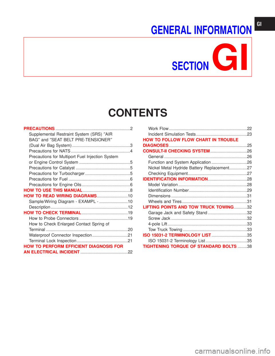
CONTENTS
PRECAUTIONS...............................................................2
Supplemental Restraint System (SRS)²AIR
BAG²and²SEAT BELT PRE-TENSIONER²
(Dual Air Bag System) .................................................3
Precautions for NATS ..................................................4
Precautions for Multiport Fuel Injection System
or Engine Control System ...........................................5
Precautions for Catalyst ..............................................5
Precautions for Turbocharger ......................................5
Precautions for Fuel ....................................................6
Precautions for Engine Oils .........................................6
HOW TO USE THIS MANUAL........................................8
HOW TO READ WIRING DIAGRAMS..........................10
Sample/Wiring Diagram - EXAMPL - ........................10
Description .................................................................12
HOW TO CHECK TERMINAL.......................................19
How to Probe Connectors .........................................19
How to Check Enlarged Contact Spring of
Terminal .....................................................................20
Waterproof Connector Inspection ..............................21
Terminal Lock Inspection ...........................................21
HOW TO PERFORM EFFICIENT DIAGNOSIS FOR
AN ELECTRICAL INCIDENT........................................22Work Flow ..................................................................22
Incident Simulation Tests ...........................................23
HOW TO FOLLOW FLOW CHART IN TROUBLE
DIAGNOSES..................................................................25
CONSULT-II CHECKING SYSTEM...............................26
General ......................................................................26
Function and System Application ..............................26
Nickel Metal Hydride Battery Replacement...............27
Checking Equipment..................................................27
IDENTIFICATION INFORMATION.................................28
Model Variation ..........................................................28
Identification Number .................................................29
Dimensions ................................................................31
Wheels and Tires .......................................................31
LIFTING POINTS AND TOW TRUCK TOWING...........32
Garage Jack and Safety Stand .................................32
Screw Jack ................................................................32
4-pole Lift ...................................................................33
Tow Truck Towing ......................................................33
ISO 15031-2 TERMINOLOGY LIST..............................35
ISO 15031-2 Terminology List ...................................35
TIGHTENING TORQUE OF STANDARD BOLTS........38
Page 1325 of 1767
Sample/Wiring Diagram Ð EXAMPL Ð
IFor Description, refer to GI-10.
YGI001
HOW TO READ WIRING DIAGRAMS
GI-10
Page 1326 of 1767
OPTIONAL SPLICE
SGI942
HOW TO READ WIRING DIAGRAMS
Sample/Wiring Diagram Ð EXAMPL Ð (Cont'd)
GI-11
Page 1327 of 1767

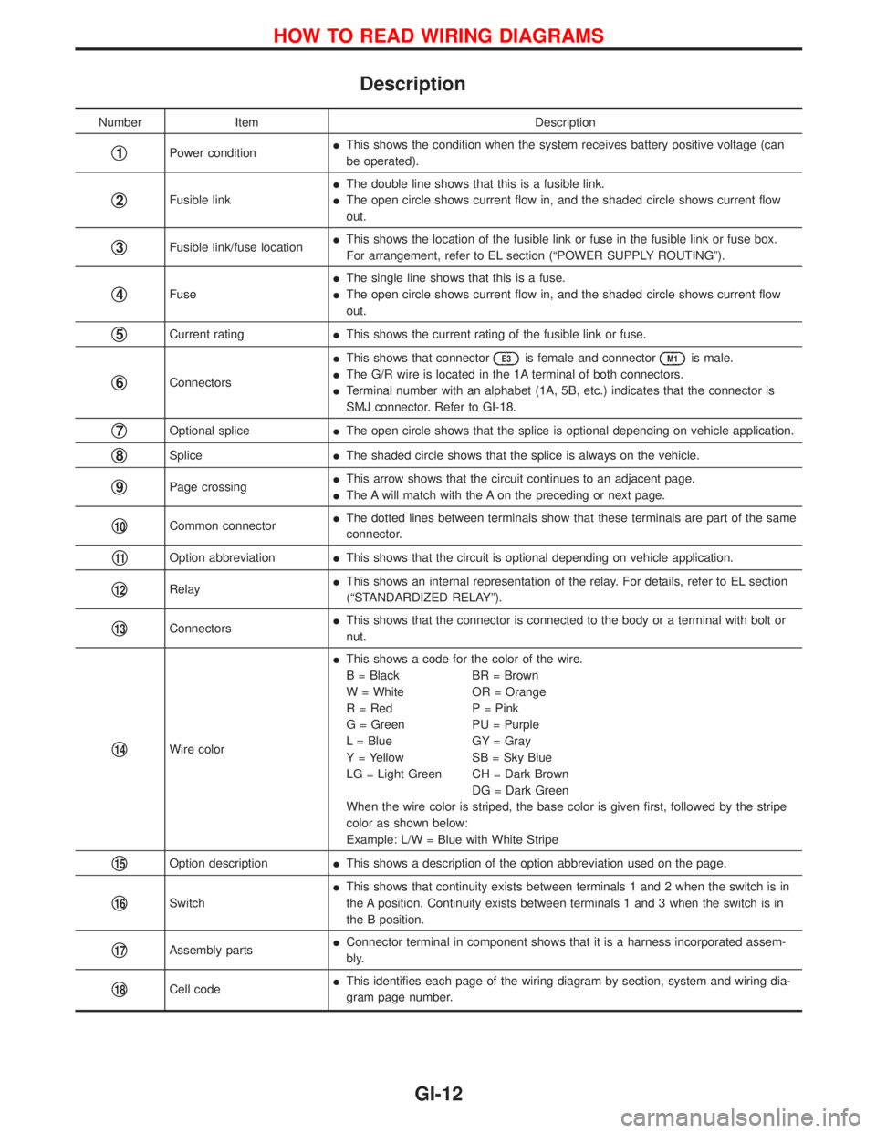
Description
Number Item Description
q1Power conditionIThis shows the condition when the system receives battery positive voltage (can
be operated).
q2Fusible linkIThe double line shows that this is a fusible link.
IThe open circle shows current flow in, and the shaded circle shows current flow
out.
q3Fusible link/fuse locationIThis shows the location of the fusible link or fuse in the fusible link or fuse box.
For arrangement, refer to EL section (ªPOWER SUPPLY ROUTINGº).
q4FuseIThe single line shows that this is a fuse.
IThe open circle shows current flow in, and the shaded circle shows current flow
out.
q5Current ratingIThis shows the current rating of the fusible link or fuse.
q6ConnectorsIThis shows that connector
E3is female and connectorM1is male.
IThe G/R wire is located in the 1A terminal of both connectors.
ITerminal number with an alphabet (1A, 5B, etc.) indicates that the connector is
SMJ connector. Refer to GI-18.
q7Optional spliceIThe open circle shows that the splice is optional depending on vehicle application.
q8SpliceIThe shaded circle shows that the splice is always on the vehicle.
q9Page crossingIThis arrow shows that the circuit continues to an adjacent page.
IThe A will match with the A on the preceding or next page.
q10Common connectorIThe dotted lines between terminals show that these terminals are part of the same
connector.
q11Option abbreviationIThis shows that the circuit is optional depending on vehicle application.
q12RelayIThis shows an internal representation of the relay. For details, refer to EL section
(ªSTANDARDIZED RELAYº).
q13ConnectorsIThis shows that the connector is connected to the body or a terminal with bolt or
nut.
q14Wire colorIThis shows a code for the color of the wire.
B = Black BR = Brown
W = White OR = Orange
R = Red P = Pink
G = Green PU = Purple
L = Blue GY = Gray
Y = Yellow SB = Sky Blue
LG = Light Green CH = Dark Brown
DG = Dark Green
When the wire color is striped, the base color is given first, followed by the stripe
color as shown below:
Example: L/W = Blue with White Stripe
q15Option descriptionIThis shows a description of the option abbreviation used on the page.
q16SwitchIThis shows that continuity exists between terminals 1 and 2 when the switch is in
the A position. Continuity exists between terminals 1 and 3 when the switch is in
the B position.
q17Assembly partsIConnector terminal in component shows that it is a harness incorporated assem-
bly.
q18Cell codeIThis identifies each page of the wiring diagram by section, system and wiring dia-
gram page number.
HOW TO READ WIRING DIAGRAMS
GI-12
Page 1328 of 1767

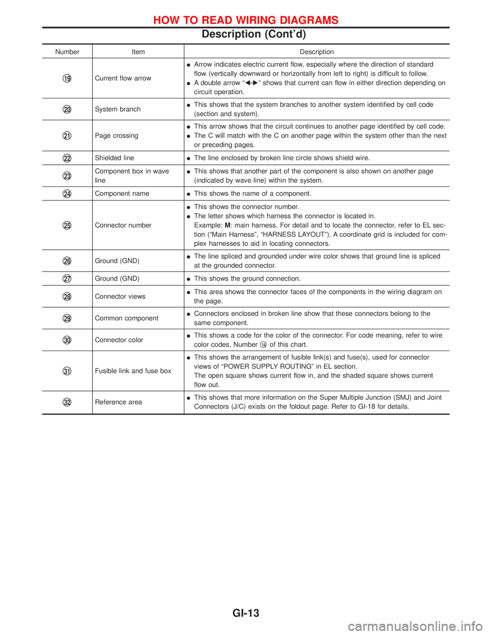
Number Item Description
q19Current flow arrowIArrow indicates electric current flow, especially where the direction of standard
flow (vertically downward or horizontally from left to right) is difficult to follow.
IA double arrow ªFÐ
Eº shows that current can flow in either direction depending on
circuit operation.
q20System branchIThis shows that the system branches to another system identified by cell code
(section and system).
q21Page crossingIThis arrow shows that the circuit continues to another page identified by cell code.
IThe C will match with the C on another page within the system other than the next
or preceding pages.
q22Shielded lineIThe line enclosed by broken line circle shows shield wire.
q23Component box in wave
lineIThis shows that another part of the component is also shown on another page
(indicated by wave line) within the system.
q24Component nameIThis shows the name of a component.
q25Connector numberIThis shows the connector number.
IThe letter shows which harness the connector is located in.
Example:M: main harness. For detail and to locate the connector, refer to EL sec-
tion (ªMain Harnessº, ªHARNESS LAYOUTº). A coordinate grid is included for com-
plex harnesses to aid in locating connectors.
q26Ground (GND)IThe line spliced and grounded under wire color shows that ground line is spliced
at the grounded connector.
q27Ground (GND)IThis shows the ground connection.
q28Connector viewsIThis area shows the connector faces of the components in the wiring diagram on
the page.
q29Common componentIConnectors enclosed in broken line show that these connectors belong to the
same component.
q30Connector colorIThis shows a code for the color of the connector. For code meaning, refer to wire
color codes, Numberq14of this chart.
q31Fusible link and fuse boxIThis shows the arrangement of fusible link(s) and fuse(s), used for connector
views of ªPOWER SUPPLY ROUTINGº in EL section.
The open square shows current flow in, and the shaded square shows current
flow out.
q32Reference areaIThis shows that more information on the Super Multiple Junction (SMJ) and Joint
Connectors (J/C) exists on the foldout page. Refer to GI-18 for details.
HOW TO READ WIRING DIAGRAMS
Description (Cont'd)
GI-13
Page 1329 of 1767
CONNECTOR SYMBOLS
Most of connector symbols in wiring diagrams are shown from the
terminal side.
IConnector symbols shown from the terminal side are enclosed
by a single line and followed by the direction mark
.
IConnector symbols shown from the harness side are enclosed
by a double line and followed by the direction mark
.
IMale and female terminals
Connector guides for male terminals are shown in black and
female terminals in white in wiring diagrams.
SGI364
SGI363
HOW TO READ WIRING DIAGRAMS
Description (Cont'd)
GI-14
Page 1330 of 1767
Harness indication
ILetter designations next to test meter probe indicate harness
(connector) wire color.
IConnector numbers in a single circle
M33indicate harness con-
nectors.
Component indication
IConnector numbers in a double circle indicate component con-
nectors.
SWITCH POSITIONS
Switches are shown in wiring diagrams as if the vehicle is in the
ªnormalº condition.
A vehicle is in the ªnormalº condition when:
Iignition switch is ªOFFº,
Idoors, hood and trunk lid/back door are closed,
Ipedals are not depressed, and
Iparking brake is released.
AGI070
SGI860
HOW TO READ WIRING DIAGRAMS
Description (Cont'd)
GI-15