Page 1331 of 1767
DETECTABLE LINES AND NON-DETECTABLE LINES
In some wiring diagrams, two kinds of lines, representing wires,
with different weight are used.
IA line with regular weight (wider line) represents a ªdetectable
line for DTC (Diagnostic Trouble Code)º. A ªdetectable line for
DTCº is a circuit in which ECM (Engine Control Module) can
detect its malfunctions with the on board diagnostic system.
IA line with less weight (thinner line) represents a ªnon-detect-
able line for DTCº. A ªnon-detectable line for DTCº is a circuit
in which ECM cannot detect its malfunctions with the on board
diagnostic system.
SGI862-A
HOW TO READ WIRING DIAGRAMS
Description (Cont'd)
GI-16
Page 1332 of 1767
MULTIPLE SWITCH
The continuity of multiple switch is described in two ways as shown
below.
IThe switch chart is used in schematic diagrams.
IThe switch diagram is used in wiring diagrams.
SGI875
HOW TO READ WIRING DIAGRAMS
Description (Cont'd)
GI-17
Page 1333 of 1767
FOLDOUT PAGE
The foldout page should be opened when reading wiring diagram.
Super multiple junction (SMJ)
In wiring diagram, connectors consisting of terminals having terminal numbers with an alphabet (1B, 0D, etc.)
are SMJ connectors.
If connector numbers are shown in Reference Area, these connector symbols are not shown in Connector
Area. For terminal arrangement of these connectors, refer to the foldout page at the end of this manual.
Joint connector
Joint connector symbols are shown in Connector Area in the wiring diagram concerned. Foldout page also
carries inside wiring layout together with such joint connector symbols.
SGI943
HOW TO READ WIRING DIAGRAMS
Description (Cont'd)
GI-18
Page 1339 of 1767

Engine compartment
There are several reasons a vehicle or engine vibration could
cause an electrical complaint. Some of the things to check for are:
IConnectors not fully seated.
IWiring harness not long enough and is being stressed due to
engine vibrations or rocking.
IWires laying across brackets or moving components.
ILoose, dirty or corroded ground wires.
IWires routed too close to hot components.
To inspect components under the hood, start by verifying the integ-
rity of ground connections. (Refer to GROUND INSPECTION
described later.) First check that the system is properly grounded.
Then check for loose connection bygently shakingthe wiring or
components as previously explained. Using the wiring diagrams
inspect the wiring for continuity.
Behind the instrument panel
An improperly routed or improperly clamped harness can become
pinched during accessory installation. Vehicle vibration can aggra-
vate a harness which is routed along a bracket or near a screw.
Under seating areas
An unclamped or loose harness can cause wiring to be pinched by
seat components (such as slide guides) during vehicle vibration. If
the wiring runs under seating areas, inspect wire routing for pos-
sible damage or pinching.
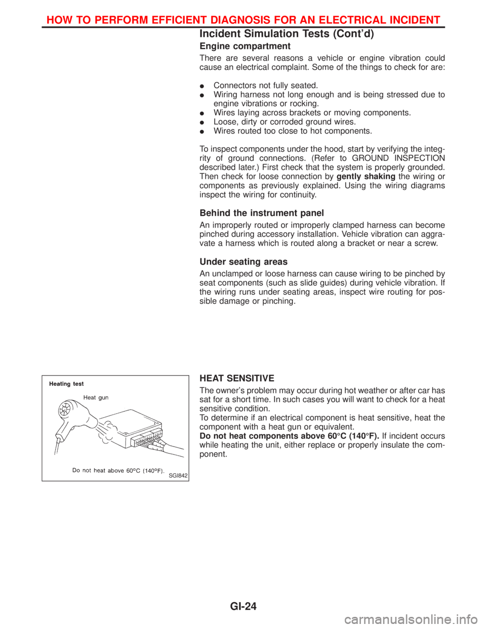
HEAT SENSITIVE
The owner's problem may occur during hot weather or after car has
sat for a short time. In such cases you will want to check for a heat
sensitive condition.
To determine if an electrical component is heat sensitive, heat the
component with a heat gun or equivalent.
Do not heat components above 60ÉC (140ÉF).If incident occurs
while heating the unit, either replace or properly insulate the com-
ponent.
SGI842
HOW TO PERFORM EFFICIENT DIAGNOSIS FOR AN ELECTRICAL INCIDENT
Incident Simulation Tests (Cont'd)
GI-24
Page 1354 of 1767

HEATER & AIR CONDITIONER
SECTION
HA
CONTENTS
PRECAUTIONS...............................................................2
Introduction ..................................................................2
Identification .................................................................2
Precautions for Working with HFC-134a (R-134a) .....3
General Refrigerant Precautions .................................3
Precautions for Refrigerant Connection ......................4
Precautions for Servicing Compressor ........................5
DESCRIPTION - Overall System...................................6
Control Operation ........................................................6
Component Layout ......................................................7
Air Flow ........................................................................8
DESCRIPTION - Refrigeration System.........................9
Refrigeration Cycle ......................................................9
PREPARATION..............................................................10
Special Service Tools ................................................10
HFC-134a (R-134a) Service Tools and
Equipment .................................................................. 11
Precautions for Service Equipment ...........................13
SERVICE PROCEDURES.............................................15
HFC-134a (R-134a) Service Procedure ....................15
Refrigerant Lines .......................................................17
Compressor Mounting ...............................................21
Belt Tension ...............................................................21
LUBRICATION OIL - Checking and Adjusting...........22
Lubrication Oil ............................................................22Maintenance of Oil Quantity in Compressor .............22
Checking and Adjusting .............................................22
COMPRESSOR - Model DKV-14C (ZEXEL make)......24
Compressor Clutch ....................................................24
DIAGNOSES - Overall System....................................27
How to Perform Trouble Diagnoses for Quick
and Accurate Repair ..................................................27
Operation Check ........................................................28
Performance Chart ....................................................30
Performance Test Diagnoses ....................................31
TROUBLE DIAGNOSES...............................................36
Symptom Chart ..........................................................36
Preliminary Check......................................................37
Harness Layout for A/C System ................................39
Wiring Diagram - Heater............................................41
Wiring Diagram ..........................................................43
Main Power Supply and Ground Circuit Check ........51
Diagnostic Procedure 1 .............................................52
Diagnostic Procedure 2 .............................................54
Diagnostic Procedure 3 .............................................59
Electrical Components Inspection .............................60
Control Linkage Adjustment.......................................61
SERVICE DATA AND SPECIFICATIONS (SDS)..........64
General Specifications ...............................................64
Inspection and Adjustment ........................................64
When you read wiring diagrams:
IRead GI section, ªHOW TO READ WIRING DIAGRAMSº.
ISee EL section, ªPOWER SUPPLY ROUTINGº for power distribution circuit.
When you perform trouble diagnoses, read GI section, ªHOW TO FOLLOW FLOW CHART IN
TROUBLE DIAGNOSESº.
Page 1394 of 1767
Wiring Diagram Ð Heater
LHD MODELS
YHA400
TROUBLE DIAGNOSES
HA-41
Page 1395 of 1767
RHD MODELS
YHA401
TROUBLE DIAGNOSES
Wiring Diagram Ð Heater (Cont'd)
HA-42
Page 1396 of 1767
Wiring Diagram
LHD TD27Ti ENGINE MODELS
YHA392
TROUBLE DIAGNOSES
HA-43