2002 NISSAN TERRANO diagram
[x] Cancel search: diagramPage 1424 of 1767

TAIL/L - Wiring diagram ..................................EL-45
TCM circuit diagram ..........................................AT-7
TCM inspection table ......................................AT-46
TDC Pulse Signal .........................................EC-168
Temperature control cable and linkage
adjustment ..................................................HA-63
THEFT - Wiring diagram...............................EL-214
Theft warning system ...........EL-209, 210, 213, 230
Thermo control amp .................................HA-51, 61
Thermostat................................................LC-12, 31
Third (3rd) seat ...............................................BT-39
THLCNT - Wiring diagram ...........................EC-435
Three way catalyst precautions.........................GI-5
Throttle control solenoid valve .....................EC-435
Throttle position switch ...................................AT-60
Tie-rod .......................................................ST-19, 21
Tie-rod ball joints.............................................ST-20
Tightening torque of standard bolts.................GI-38
Time control system .....................EL-180, 182, 184
Timing chain ...................................................EM-26
Timing gear ....................................................EM-38
Tire rotation ....................................................MA-43
Tooth contact diff. .....................................PD-27, 52
Torque convertor clutch solenoid valve ..AT-72, 141
Torsion bar spring .......................................FA-4, 30
Tow truck towing ..............................................GI-33
Towing point.....................................................GI-34
Transaxle fluid replacement.....................MA-36, 37
Transfer case ..............................................TF-9, 12
Transfer fluid replacement (Part time
4WD model) .........................................MA-36, 37
Transfer oil replacement ..........................MA-36, 38
Transmission case (M/T)..........................MT-10, 14
TRANSMT - Wiring diagram ...........................EL-80
Tread-FR&RR (Dimensions)............................GI-25
Trim...............................................BT-18, 19, 20, 21
Trunk room trim...............................................BT-47
Turbocharger ..................................................EM-14
Turbocharger charge air cooler......................EM-11
Turbocharger precautions..................................GI-5
TURN - Wiring diagram ..................................EL-56
Turn signal lamp .......................................EL-55, 56
U
Under body .....................................................BT-53
Upper link (front susp.) ...................................FA-33
V
Vacuum hose (brake system) ........................BR-19Vacuum hose drawing (Engine
control)................................................EC-18, 304
Vacuum pump .............................EM-24, BR-23, 25
Valve clearance..............................................EM-35
Valve clearance adjustment.....................MA-20, 28
Valve guide ....................................................EM-59
Valve lifter ......................................................EM-32
Valve seat ......................................................EM-60
Valve spring ...................................................EM-61
Variable nozzle turbocharger control
solenoid valve ...........................................EC-281
Vehicle identification number...........................GI-29
Vehicle speed sensor (VSS) ..................EC-99, 397
Ventilator door control rod adjustment ...........HA-61
Viscosity number (SAE)...........................MA-17, 18
VNT - Wiring diagram ..................................EC-283
VSS - Wiring diagram ..................................EC-101
W
WARN - Wiring diagram ...........................EL-82, 93
Warning chime ..........................................EL-81, 93
Warning lamps ..........................................EL-81, 82
Washer, front ...................................................EL-94
Washer, rear....................................................EL-96
Water cock control rod adjustment ................HA-63
Water pump ..............................................LC-11, 29
Water temperature gauge ...............................EL-72
Weatherstrip - See Exterior ............................BT-21
Wheel alignment (front) ....................................FA-8
Wheel balance ...............................................MA-43
Wheel bearing (front axle) ................................FA-6
Wheel bearing (rear) ..................................RA-5, 16
Wheel hub (front) ........................................FA-4, 18
Wheel sensors (ABS)...............................BR-38, 42
Wheel size .......................................................GI-31
WINDOW - Wiring diagram ..........................EL-134
Window, back door .........................................BT-47
Window, door ..................................................BT-42
Window, rear side .....................................BT-42, 43
Window, side - See Rear side window ...........BT-43
Windshield.......................................................BT-42
WIP/R - Wiring diagram ..................................EL-96
WIPER - Wiring diagram ........................EL-94, 100
Wiper and washer.....................................EL-94, 98
Wiper, front......................................................EL-94
Wiper, rear ......................................................EL-96
Wiring Diagram (Cell code) list .....................EL-291
ALPHABETICAL INDEX
IDX-7
Page 1515 of 1767

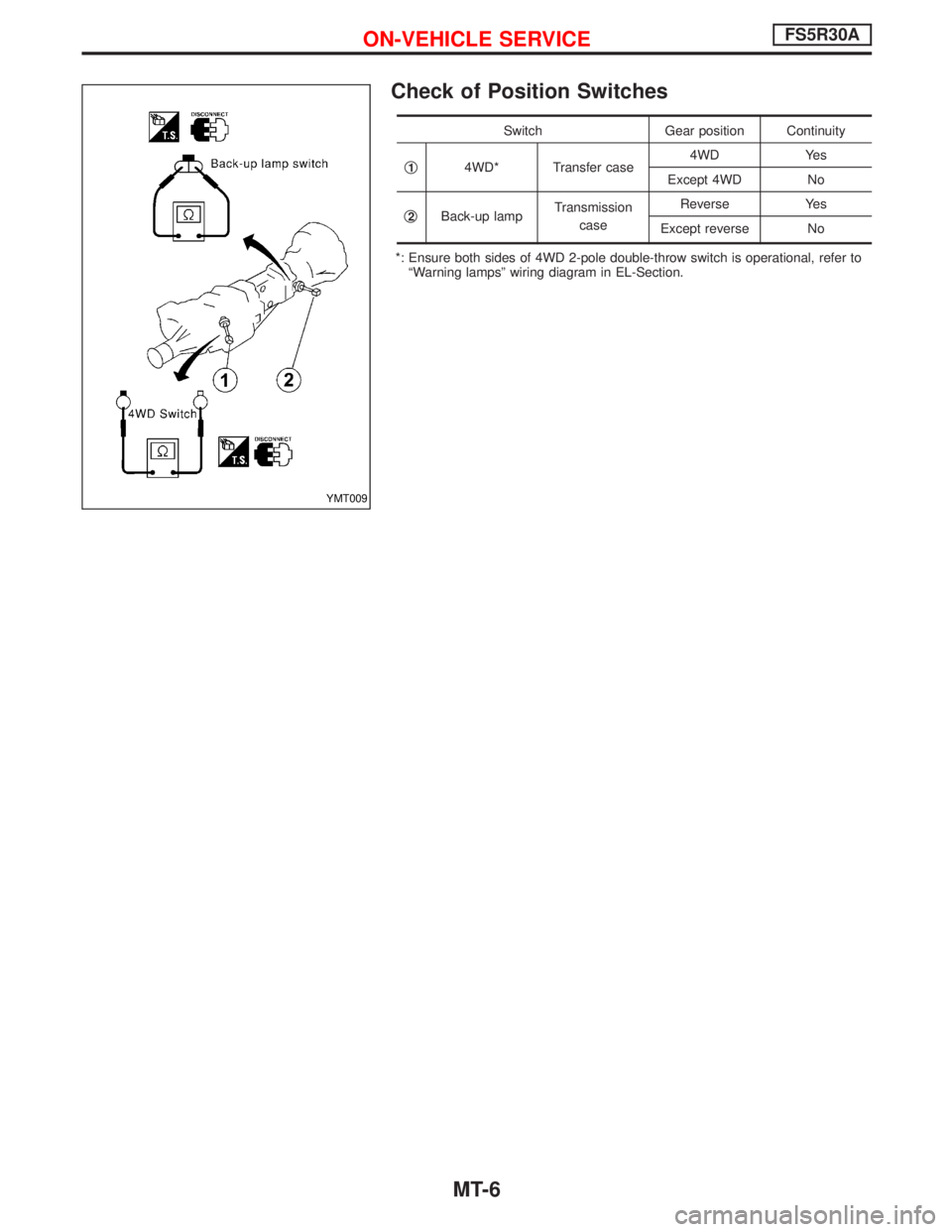
Check of Position Switches
Switch Gear position Continuity
q
14WD* Transfer case4WD Yes
Except 4WD No
q
2Back-up lampTransmission
caseReverse Yes
Except reverse No
*: Ensure both sides of 4WD 2-pole double-throw switch is operational, refer to
ªWarning lampsº wiring diagram in EL-Section.
YMT009
ON-VEHICLE SERVICEFS5R30A
MT-6
Page 1622 of 1767

RESTRAINT SYSTEM
SECTION
RS
CONTENTS
SEAT BELTS...................................................................2
Precautions ..................................................................2
Front Seat Belt.............................................................4
SUPPLEMENTAL RESTRAINT SYSTEM (SRS)............6
Precautions ..................................................................6
Preparation ..................................................................7
SRS Configuration .......................................................8
Seat Belt Pre-tensioner with Load Limiter...................9
Built-in Type Side Air Bag............................................9
SRS Component Parts Location ...............................10
Maintenance Items ....................................................10
Diagnosis Sensor Unit ............................................... 11
Front Seat Belt Pre-tensioner ....................................12
Side Air Bag (Satellite) Sensor ..................................13
Driver Air Bag Module and Spiral Cable ...................14
Front Passenger Air Bag Module ..............................17Front Side Air Bag Module ........................................18
Disposal of Air Bag Module and Seat Belt Pre-
tensioner ....................................................................20
Trouble Diagnoses Introduction.................................26
How to Perform Trouble Diagnoses for Quick
and Accurate Repair ..................................................29
Schematic ..................................................................31
Wiring Diagram - SRS -.............................................32
SRS Operation Check ...............................................36
Trouble Diagnoses with CONSULT-II..................37
Trouble Diagnoses without CONSULT-II.............46
Trouble Diagnoses:²AIR BAG²Warning Lamp
Does Not Turn Off .....................................................54
Trouble Diagnoses:²AIR BAG²Warning Lamp
Does Not Turn On .....................................................56
Collision Diagnosis ....................................................57
Page 1627 of 1767

Precautions
SUPPLEMENTAL RESTRAINT SYSTEM (SRS) ªAIR BAGº AND ªSEAT BELT
PRE-TENSIONERº
The Supplemental Restraint System such as ªAIR BAGº and ªSEAT BELT PRE-TENSIONERº used along with
a seat belt, helps to reduce the risk or severity of injury to the driver and front passenger for certain types of
collision. The SRS composition which is available to NISSAN MODEL R20 is as follows (The composition
varies according to the destination and optional equipment.):
IFor a frontal collision
The Supplemental Restraint System consists of driver air bag module (located in the center of the steer-
ing wheel), front passenger air bag module (located on the instrument panel on passenger side), front seat
belt pre-tensioners, a diagnosis sensor unit, warning lamp, wiring harness and spiral cable.
IFor a side collision
The Supplemental Restraint System consists of front side air bag module (located in the outer side of front
seat), side air bag (satellite) sensor, diagnosis sensor unit (one of components of air bags for a frontal
collision), wiring harness, warning lamp (one of components of air bags for a frontal collision).
WARNING:
ITo avoid rendering the SRS inoperative, which could increase the risk of personal injury or death
in the event of a collision which would result in air bag inflation, all maintenance should be per-
formed by an authorized NISSAN dealer.
IImproper maintenance, including incorrect removal and installation of the SRS, can lead to per-
sonal injury caused by unintentional activation of the system.
IDo not use electrical test equipment on any circuit related to the SRS unless instructed to in this
Service Manual. Spiral cable and wiring harnesses covered with yellow insulation tape either just
before the harness connectors or for the complete harness are related to the SRS.
PRECAUTIONS FOR SRS ªAIR BAGº AND ªSEAT BELT PRE-TENSIONERº SERVICE
IDo not use electrical test equipment to check SRS circuits unless instructed to in this Service Manual.
IBefore servicing the SRS, turn ignition switch ªOFFº, disconnect both battery cables and wait at least 3
minutes.
For approximately 3 minutes after the cables are removed, it is still possible for the air bag and seat belt
pre-tensioner to deploy. Therefore, do not work on any SRS connectors or wires until at least 3 minutes
have passed.
IDiagnosis sensor unit must always be installed with their arrow marks ª+º pointing towards the front of
the vehicle for proper operation. Also check diagnosis sensor unit for cracks, deformities or rust before
installation and replace as required.
IThe spiral cable must be aligned with the neutral position since its rotations are limited. Do not attempt to
turn steering wheel or column after removal of steering gear.
IHandle air bag module carefully. Always place driver and front passenger air bag modules with the pad
side facing upward and place front side air bag module (built-in type) standing with stud bolt side setting
bottom.
IConduct self-diagnosis to check entire SRS for proper function after replacing any components.
IAfter air bag inflates, the front instrument panel assembly should be replaced if damaged.
WIRING DIAGRAMS AND TROUBLE DIAGNOSIS
When you read wiring diagrams, refer to the following:
IGI-10, ªHOW TO READ WIRING DIAGRAMSº
IEL-6, ªPOWER SUPPLY ROUTINGº for power distribution circuit
When you perform trouble diagnosis, refer to the following:
IGI-25, ªHOW TO FOLLOW TEST GROUPS IN TROUBLE DIAGNOSISº
IGI-22, ªHOW TO PERFORM EFFICIENT DIAGNOSES FOR AN ELECTRICAL INCIDENTº
SUPPLEMENTAL RESTRAINT SYSTEM (SRS)
RS-6
Page 1653 of 1767

Wiring Diagram Ð SRS Ð
YRS065
SUPPLEMENTAL RESTRAINT SYSTEM (SRS)
RS-32
Page 1654 of 1767

YRS066
SUPPLEMENTAL RESTRAINT SYSTEM (SRS)
Wiring Diagram Ð SRS Ð (Cont'd)
RS-33
Page 1655 of 1767

MODELS WITH FRONT SEAT BELT PRE-TENSIONER B52, B53
YRS067
SUPPLEMENTAL RESTRAINT SYSTEM (SRS)
Wiring Diagram Ð SRS Ð (Cont'd)
RS-34
Page 1656 of 1767

YRS068
SUPPLEMENTAL RESTRAINT SYSTEM (SRS)
Wiring Diagram Ð SRS Ð (Cont'd)
RS-35